Table of Contents
Advertisement
Quick Links
IMC2000/200 Series
Industrial Switching Media Converters
AT-IMC2000TP/SP
AT-IMC2000TP/SC
AT-IMC2000T/SP
AT-IMC2000T/SC
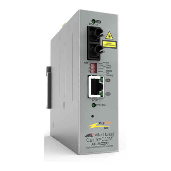
AT-IMC200TP/SC
AT-IMC200T/SC
Installation Guide
613-002626 Rev A
PORT 2
SFP
OFF
ON
OFF
1
SML
2
FORCE
3
100FD
NOT USED
PORT 1
SYSTEM
AT-IMC2000
Industrial Media Converter
Industrial Media Converter
PORT 2
TX
RX
OFF
ON
OFF
1
SML
2
FORCE
3
100FD
NOT USED
PORT 1
SYSTEM
AT-IMC200
Industrial Media Converter
Industrial Media Converter
PORT 2
PORT 2
SFP
SML
ON
FORCE
1
100FD
2
REMOTE
3
PoE
CONTROL
OFF
1
2
3
PORT 1
SYSTEM
60W
AT-IMC2000
AT-IMC2000
Industrial Media Converter
PORT 2
PORT 2
TX
RX
SML
ON
OFF
FORCE
1
1
100FD
2
2
REMOTE
3
3
PoE
CONTROL
PORT 1
SYSTEM
60W
AT-IMC2000
AT-IMC200
Industrial Media Converter
TX
RX
ON
SML
FORCE
100FD
NOT USED
PORT 1
SYSTEM
TX
RX
SML
ON
FORCE
100FD
REMOTE
PoE
CONTROL
PORT 1
SYSTEM
60W
4533
Advertisement
Table of Contents


Need help?
Do you have a question about the IMC2000 Series and is the answer not in the manual?
Questions and answers