Allied Telesis AT-MC13 Installation Manual
Ethernet media converters
Hide thumbs
Also See for AT-MC13:
- Installation manual (48 pages) ,
- User manual (30 pages) ,
- Specifications (2 pages)

Related Manuals for Allied Telesis AT-MC13


Summary of Contents for Allied Telesis AT-MC13
-
Page 1: Installation Guide
AT-MC13 AT-MC14 AT-MC15 AT-MC16 Ethernet Media Converters Installation Guide PN 613-10724-00 Rev C... - Page 2 Telesyn International Corp. be liable for any incidental, special, indirect, or consequential damages whatsoever, including but not limited to lost profits, arising out of or related to this manual or the information contained herein, even if Allied Telesyn International Corp. International Corp. has been advised of, known, or should have...
-
Page 3: Electrical Safety And Emission Compliance Statement
Declares that the product: Ethernet Media Converters Model Numbers: AT-MC13, AT-MC14, AT-MC15, AT-MC16 This product complies with FCC Part 15B, Class B Limits: This device complies with part 15 of the FCC Rules. Operation is subject to the following two conditions: (1) This device must not cause harmful interference, and (2) this device must accept any interference received, including interference that may cause undesired operation. - Page 4 EN55024 Warning : This product requires shielded cables to (AT-MC13, AT-MC14, AT-MC16) comply with emission and immunity standards. If it is used with unshielded cables, the user may be required to take measures to correct the interference problem at their own expense.
-
Page 5: Table Of Contents
Welcome to Allied Telesyn ........ - Page 6 Chapter 3 Troubleshooting ..........19 Appendix A Technical Specifications .
-
Page 7: Welcome To Allied Telesyn
Ethernet Media Converters. Where to Find Web-based Guides The Allied Telesyn web site at www.alliedtelesyn.com provides you with an easy way to access the most recent documentation and technical information for all of our products. For product guides, you can go directly to the following web page: www.alliedtelesyn.com/support/prd_libs.htm. -
Page 8: Contacting Allied Telesyn Technical Support
You can request technical support online by filling out the Online Technical Support Form at www.alliedtelesyn.com/support/supportf.asp or by accessing the Technical Support Knowledge Base from Allied Telesyn’s North American web site. You can use the Knowledge Base to submit questions to our technical support staff and review answers to previously asked questions. -
Page 9: Technical Support E-Mail Addresses
Returning Products Products for return or repair must first be assigned a Return Materials Authorization (RMA) number. A product sent to Allied Telesyn without a RMA number will be returned to the sender at the sender’s expense. To obtain an RMA number, contact Allied Telesyn’s Technical Support at one... -
Page 10: For Sales Or Corporate Information
Welcome to Allied Telesyn For Sales or Corporate Information You can contact Allied Telesyn for sales or corporate information at one of the locations below: Allied Teleyn International Corp. 19800 North Creek Parkway, Suite 200 Bothell, WA 98011 Tel: 1 (425) 487-8880 Fax: 1 (425) 489-9191 Allied Telesyn International Corp. -
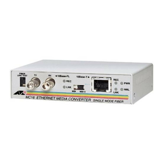
Page 11: Overview
The AT-MC1x Series Media Converters allow you to interconnect LAN devices over large distances. The AT-MC13, AT-MC14, and AT-MC16 media converters feature a 10Base-T twisted pair port and a 10Base-F fiber optic port. The twisted pair port has an RJ-45 connector and a maximum operating distance of 100 meters (328 feet). - Page 12 10Base-F LINK TEST MDI-X MC13 ETHERNET MEDIA CONVERTER Figure 1 AT-MC1x Series Media Converter (AT-MC13 model) Table 1 lists the maximum operating distances for the AT-MC13, AT-MC14, and the AT-MC16 media converters. Table 1 Maximum Operating Distances 10Base-F 10Base-T Model...
-
Page 13: Key Features
Green A link has been established on the port. Green Data is being received. AT-MC13, AT-MC14 and AT-MC16 only Green The MissingLink feature is enabled and the media converter is functioning in normal operating mode. The MissingLink feature is disabled and the media converter is... -
Page 14: Mdi/Mdi-X Switch
Table 3 Status LEDs for the Media Converters (Continued) Color Description AT-MC15 Only Green Data is being transmitted on the BNC port. Green Data is being received on the BNC port. ONLINE Green The BNC port is connected to an active 10Base2 segment. Green The BNC port is sensing a collision signal. -
Page 15: Fiber Link Test Switch
AT-MC1x Series Installation Guide Fiber Link Test Switch The AT-MC13, AT-MC14, and AT-MC16 media converters feature a Fiber Link Test switch. This switch sets the fiber port into an artificial link transmission state for testing without the twisted pair port being connected. When the Fiber Link Test switch is in the DOWN (default) position, the NML LED is green indicating that the media converter is functioning normally. -
Page 16: Auto-Negotiation
The best network performance is achieved when an end-node can operate in full-duplex mode. The AT-MC13, AT-MC14, and AT-MC16 media converters can operate in either full- or half-duplex mode. However, it is important to note that the end-... -
Page 17: Missinglink
AT-MC1x Series Installation Guide MissingLink The MissingLink feature enables the ports on the media converter to pass the “Link” status of their connections to each other. When the media converter detects a problem with one of the ports, such as the loss of connection to a end- node, the media converter shuts down the connection to the other port, thus notifying the end-node that the connection has been lost. -
Page 18: Terminator Switch (At-Mc15 Only)
Terminator Switch (AT-MC15 Only) The Terminator switch on the AT-MC15 media converter offers 50 termination without the use of a T-connector and 50 barrel terminator. Only end-point nodes need 50 termination. Internal nodes on a thinnet segment should be connected to the cable through standard 10Base2 T-connectors. Refer to Figure 3 for the location of the Terminator switch. -
Page 19: External Ac/Dc Power Adapter
120 and 240 V AC versions with an unregulated output of 12 V DC at 1 A. The power requirement for the AT-MC13, AT-MC14, and AT-MC16 media converters is 12 V DC, 500 mA. The power requirement for the... -
Page 20: Network Topologies
Both types of topologies are described below. Standalone Topology A standalone topology uses one media converter between the end-nodes. Figure 5 illustrates a standalone topology that uses an AT-MC13 media converter to connect two switches. 10Base-F Fiber Optic Switch 2 km (1.2 mi) -
Page 21: Back-To-Back Topology
AT-MC1x Series Installation Guide Back-to-Back Topology In some network configurations you may want to interconnect two media converters in what is referred to as a back-to-back topology. In this topology, the media converters not only extend the distance of your network but also convert the fiber optic cable from twisted pair to fiber optic and back again. -
Page 23: Installing The Media Converter
The end-nodes connected to the media converter must operate at 10 Mbps. The end-nodes connected to the ports of the AT-MC13, AT-MC14, and the AT-MC16 must be able to operate in the same duplex mode. These units can operate in either full- or half-duplex mode. - Page 24 Table 7 Fiber Optic Port Specifications (Full-duplex) Maximum Maximum Operating Model Connector Cable Allowable Loss Distance Budget AT-MC13 62.5/125 micron 2 km (1.2 mi) 20 dB at 850 nm multimode AT-MC14 62.5/125 micron 2 km (1.2 mi) 20 dB at 850 nm...
-
Page 25: Reviewing Safety Precautions
Please review the following safety precautions before you begin to install the media converter. Caution Power to the hub must be sourced only from the adapter. Warning (AT-MC13, AT-MC14) This is a “CLASS 1 LED PRODUCT” (AT-MC16) Class 1 laser product. Warning Do not stare into the laser beam. Warning Lightning Danger: Do not work on equipment or cables during periods of lightening activity. -
Page 26: Installing The Media Converter
Place the media converter on a level, secure surface (such as a desk or table), leaving ample space around the unit for ventilation. For an AT-MC13, AT-MC14, or AT-MC16, remove the dust cover from the fiber optic connector and connect the cable to the fiber optic port. Verify... -
Page 27: Warranty Registration
AT-MC1x Series Installation Guide Connect the twisted pair cable to the 10Base-T port. Set the MDI/MDI-X switch as follows: — If you are connecting a workstation to the twisted pair port, set the MDI/MDI-X switch to the MDI-X position. (MDI-X is the default position.) —... -
Page 29: Troubleshooting
Category 3 or better cable. Verify that the end-node is operating at 10 Mbps and full- or half-duplex mode if connected to an AT-MC13, AT-MC14, or AT-MC16. Verify that the end-node is operating at 10 Mbps and half-duplex... - Page 30 If the LNK LED for the fiber optic port is OFF, do the following: Verify that the end-node connected to the port is ON and is operating properly. Check that the fiber optic cable is securely connected to the fiber optic port on the media converter and on the remote end-node.
- Page 31 Refer to Table 7 on page 14 for the fiber optic port specifications. If the NML LED on the AT-MC13, AT-MC14, or AT-MC16 is OFF, do the following: Check that the end-nodes connected to the media converter are powered ON.
-
Page 33: Technical Specifications
-25° C to 70° C (-13° F to 158° F) Relative Humidity: 5% to 95% non-condensing Operating Altitude: Up to 3,048 meters (10,000 feet) Electrical Rating Input Supply Voltage: 12 V DC Maximum Current: Power Consumption: AC Input Voltage: AT-MC13, AT-MC14, AT-MC16 500 mA AT-MC15 300 mA... -
Page 34: Agency Certifications
Agency Certifications EMI/RFI: FCC Class A, IC Class A, EN 55022 Class B Safety: UL, CSA, TUV, IEC 825-1 CE Compliant Immunity: EN50082-1 1997 Immunity Standard... -
Page 35: Translated Safety And Emission Information
Appendix B Translated Safety and Emission Information Important: This appendix contains multiple-language translations for the safety statements in this guide. Wichtig: Dieser Anhang enthält Übersetzungen der in diesem Handbuch enthaltenen Sicherheitshinweise in mehreren Sprachen. Vigtigt: Dette tillæg indeholder oversættelser i flere sprog af sikkerhedsadvarslerne i denne håndbog. - Page 36 Declares that the product: Ethernet Media Converters Model Numbers: AT-MC13, AT-MC14, AT-MC15, AT-MC16 This product complies with FCC Part 15B, Class B Limits: This device complies with part 15 of the FCC Rules. Operation is subject to the following two conditions: (1) This device must not cause harmful interference, and (2) this device must accept any interference received, including interference that may cause undesired operation.
- Page 37 EN55024 Warning : This product requires shielded cables (AT-MC13, AT-MC14, AT-MC16) to comply with emission and immunity standards. If it is used with unshielded cables, the user may be required to take measures to correct the interference problem at their own expense.
- Page 38 Störsicherheit EN55024 Für dieses Produkt sind abgeschirmte Kabel Achtung (AT-MC13, AT-MC14, AT-MC16) erforderlich, damit den Richtlinien für Emission und Interferenzschutz entsprochen wird. Falls das Produkt mit nicht abgeschirmten Kabeln verwendet wird, können weitergehende Maßnahmen für die Korrektur von Interferenzproblemen auf Kosten des Benutzers notwendig werden.
- Page 39 Immunitet EN55024 Advarsel : Dette produkt skal bruges med (AT-MC13, AT-MC14, AT-MC16) afskærmede kabler for at overholde bestemmelserne vedrørende udstråling og støjimmunitet. Hvis det bruges med uafskærmede kabler, kan det blive påkrævet af brugeren at korrigere interferensproblemer for egen regning.
- Page 40 EN55024 Waarschuwing Om te voldoen aan de emissie- en AT-MC13, AT-MC14, AT-MC16) immuniteitsnormen dient dit apparaat te zijn voorzien van afgeschermde kabels. Als het met niet-afgeschermde kabels wordt gebruikt, kan het zijn dat de gebruiker maatregelen moet treffen om interferentieproblemen voor eigen rekening op te lossen.
- Page 41 EN55024 Il faut utiliser des câbles blindés pour Avertissement (AT-MC13, AT-MC14, AT-MC16) ce produit afin de respecter les normes d’émission et d’immunité. Si l’utilisateur choisit d’utiliser des câbles non blindés, il sera peut-être contraint de prendre les mesures nécessaires pour corriger les problèmes d’interférences, ainsi que d’assumer le coût correspondant.
- Page 42 EN55022 Luokka B Kestävyys EN55024 Varoitus : Tämä tuote vaatii suojattuja (AT-MC13, AT-MC14, AT-MC16) kaapeleita toimiakseen emissio- ja häiriönsietostandardien mukaisesti. Jos tuotetta käytetään ilman suojattuja kaapeleita, käyttäjä voi joutua korjaamaan häirinnän aiheuttaman ongelman omalla kustannuksellaan. Sähköturvallisuus TUV-EN60950, UL1950, CSA 950 TURVALLISUUS Tähtipisteeseen (hub) syötettävän virran pitää...
- Page 43 Immunità EN55024 questo prodotto, se utilizzato con cavi Avvertenza (AT-MC13, AT-MC14, AT-MC16) schermati, è conforme alle norme sulle emissioni e sull’immunità. In caso di uso senza cavi schermati, l’utente può dover adottare a proprie spese misure correttive contro le interferenze.
- Page 44 EN55022 Klasse B Immunittet EN55024 Advarsel : Dette produktet må brukes med (AT-MC13, AT-MC14, AT-MC16) vernede kabler for å tilfredsstille emisjons- og fritakelsesstandarder. Dersom produktet brukes med uvernede kabler, må brukeren muligens rette forstyrrelsesproblemene for egen regning. Elektrisk sikkerhet TUV-EN60950, UL1950, CSA 950 SIKKERHET All strømtilførsel må...
- Page 45 EN55024 Advertência : Este produto requer a utilização (AT-MC13, AT-MC14, AT-MC16) de cabos blindados para cumprimento dos standards de limites de emissão e imunidade. Se o produto for utilizado com cabos não blindados, o utilizador poderá necessitar de tomar medidas para correcção de problemas de interferência, por sua própria conta.
- Page 46 SEGURIDAD La energía para el dispositivo central o “hub” debe provenir únicamente del adaptador. EUROPE - EC (AT-MC13, AT-MC14, AT-MC16) Utilizar un adaptador de corriente alterna autorizado TÜV de 12 Vdc, 500 EUROPE - EC (AT-MC15) Utilizar un adaptador de corriente alterna autorizado TÜV de 12 Vdc, 300...
- Page 47 Immunitet EN55024 Denna produkt kräver skärmade kablar för Varning (AT-MC13, AT-MC14, AT-MC16) att uppfylla standardkraven för emission och immunitet. Om den används med oskärmade kablar kan användaren vara tvungen att vidta åtgärder på egen bekostnad för att åtgärda störningsproblemet. Elsäkerhet TUV-EN60950, UL1950, CSA 950 SÄKERHET...
- Page 48 Translated Safety and Emission Information Varning: NÄTKABELN ANVÄNDS SOM STRÖMBRYTARE FÖR ATT KOPPLA FRÅN STRÖMMEN, dra ur nätkabeln. FARA FÖR BLIXTNEDSLAG Fara: ARBETA EJ på utrustningen eller kablarna vid ÅSKVÄDER. Blockera inte luftventilerna. Koppla inte telefonledning till signalkontakten. Driftstemperatur: Denna produkt är konstruerad för rumstemperatur ej överstigande 40 grader Celsius.
-
Page 49: Technical Support Fax Order Form
Conditions (List the steps that led up to the problem.) ______________________________________________________________________ ______________________________________________________________________ ______________________________________________________________________ ______________________________________________________________________ Detailed description (Use separate sheet, if necessary) ______________________________________________________________________ ______________________________________________________________________ ______________________________________________________________________ When completed, fax this sheet to the appropriate Allied Telesyn office. Fax numbers can be found on page viii.
Need help?
Do you have a question about the AT-MC13 and is the answer not in the manual?
Questions and answers