
Related Manuals for ADLINK Technology NuDAM-6050


Summary of Contents for ADLINK Technology NuDAM-6050
- Page 1 NuDAM-6050 NuDAM-6052 NuDAM-6053 NuDAM-6054 NuDAM-6056 NuDAM-6058 NuDAM-6060 NuDAM-6063 Digital I/O Modules Recycled Paper...
- Page 3 Trademarks ND-6050, ND-6052, ND-6053, ND-6054, ND-6056, ND6058, ND-6060 and ND-6063 are registered trademarks of ADLink Technology Inc., IBM PC is a registered trademark of International Business Machines Corporation. Intel is a registered trademark of Intel Corporation.
- Page 4 Getting service from ADLINK ♦Customer Satisfaction is always the most important thing for ADLINK Tech Inc. If you need any help or service, please contact us and get it. ADLINK Technology Inc. http://www.adlink.com.tw Web Site http://www.adlinktechnology.com Sales & Service service@Adlink.com.tw NuDAQ nudaq@adlink.com.tw...
-
Page 5: Table Of Contents
Table of Contents Chapter 1 Introduction ............. 1 About the NuDAM DIO Modules ..........1 Overview of NuDAM-6050 ............2 1.2.1 What is NuDAM-6050? ............2 1.2.2 Features of NuDAM-6050 ...........2 1.2.3 Specifications of NuDAM-6050 ...........2 1.2.4 A Look at ND-6050 & Pin Assignment ........4 1.2.5... - Page 6 2.3.1 Equipments for Install a New Module........49 2.3.2 Installing Procedures............49 Application Wiring for NuDAM-6050 ........50 Application Wiring for NuDAM-6052 ........51 Application Wiring for NuDAM-6053 ........52 Application Wiring for NuDAM-6054 ........53 Application Wiring for NuDAM-6056 ........53 Application Wiring for NuDAM-6058 ........
- Page 7 3.1.1 Introduction .................57 3.1.2 Document Conventions............58 3.1.3 Format of NuDAM Commands..........58 3.1.4 Response of NuDAM Commands ........59 Summary of Command Set............. 60 Set Configuration..............62 Read Configuration ..............64 Read Module Name ..............66 Read Firmware Version ............67 Reset Status................68 Digital Output................
-
Page 9: Chapter 1 Introduction
The NuDAM provides a series of digital input or output (DIO) modules to sense the digital signal or to control the remote devices. The specified features of each module are shown here. • NuDAM-6050 : Digital I/O module • NuDAM-6052 : Isolated digital input module •... -
Page 10: Overview Of Nudam-6050
Overview of NuDAM-6050 1.2.1 What is NuDAM-6050? NuDAM-6050 is a digital input and output module. The digital input channels can monitor active TTL signals, and sense passive switch on/off signal because of the internal pull high resistors. The convenient open collector output channels can sink up to 50 mA current. - Page 11 ♦ Digital Output • Channel numbers : 8 • Output characteristic : open collector transistor • Maximum current sink : 50mA • Max. power dissipation : 300mW ♦ Watchdog Function • Module internal watchdog timer: 150 ms • Power failure threshold : 4.65 V •...
-
Page 12: A Look At Nd-6050 & Pin Assignment
1.2.4 A Look at ND-6050 & Pin Assignment Digital Input/Output ND-6050 Signal I/O Type Digital Output Bit 0-7 Bit 0-6 Digital Input 4 • Introduction... -
Page 13: Pin Definitions Of Nudam-6050
1.2.5 Pin Definitions of NuDAM-6050 Pin # Signal Name Description DO 7 Digital output channel 7 DO 6 Digital output channel 6 DO 5 Digital output channel 5 DO 4 Digital output channel 4 DO 3 Digital output channel 3... -
Page 14: Nd-6050 Functional Block Diagram
1.2.6 ND-6050 Functional Block Diagram + 5V Power Input +10V ~ +30V Power Regulator & Filter 8-bit Digital/Output Watchdog/Power Failure Supervisor Data + 7-bit Digital/Input RS-485 Micro Data - Rec/Drv Processor Default* 1-bit Digital/Input EEPROM Config Data Safe Value 6 • Introduction... -
Page 15: Overview Of Nudam-6052
Overview of NuDAM-6052 1.3.1 What is NuDAM-6052 ? NuDAM-6052 provides 8 isolated digital input channels. Six of the input channels are differential type and two of them are single-ended with common ground. The isolation voltage is up to 5000 Vrms. It is suitable to use NuDAM-6052 in industrial environment with the dangerous of high voltage electric shock. - Page 16 • Safe value : 8 output channels • Host programmable watchdog :100 ms ~ 25.5 sec ♦ Power • Power supply : +10V to +30V • Current consumption : 0.4 W 8 • Introduction...
-
Page 17: A Look At Nd-6052 & Pin Assignment
1.3.4 A Look at ND-6052 & Pin Assignment Isolated Digital Input ND-6052 Channels Input Type Diffential Single Ended Introduction • 9... -
Page 18: Pin Definitions Of Nudam-6052
1.3.5 Pin Definitions of NuDAM-6052 Pin # Signal Name Description DI5+ Digital Input Channel 5+ DI5 - Digital Input Channel 5 - DI6+ Digital Input Channel 6+ D.GND Digital Input Ground DI7+ Digital Input Channel 7+ Default* Initial state setting (Y) DATA+ RS-485 series signal, positive (G) DATA-... -
Page 19: Nd-6052 Functional Block Diagram
1.3.6 ND-6052 Functional Block Diagram Power Input +10V ~ +30V Power Regulator & Filter DI0+ Watchdog/Power Failure Supervisor DI0- DI0+ RS-485 Micro Data - DI0- Rec/Drv Processor DI5+ EEPROM DI5- Config Data Safe Value DI6+ D.GND DI7+ D.GND Introduction • 11... -
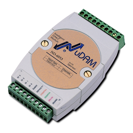
Page 20: Overview Of Nudam-6053
Overview of NuDAM-6053 1.4.1 What is NuDAM-6053 ? NuDAM-6053 provides 16 digital input channels for dry contact or wet contact signals. The effective distance from DI to contact point is up to 500m for dry contact input. 1.4.2 Features of NuDAM-6053 •... - Page 21 • Power failure threshold : 4.65 V • Host programmable watchdog : 100 ms ~ 25.5 sec ♦ Power • Power supply : +10V to +30V • Current consumption : 0.4 W Introduction • 13...
-
Page 22: A Look At Nd-6053 & Pin Assignment
1.4.4 A Look at ND-6053 & Pin Assignment 16-CH ND-6053 Digital Input Type Channels Digital Input 14 • Introduction... -
Page 23: Pin Definitions Of Nudam-6053
1.4.5 Pin Definitions of NuDAM-6053 Pin # Signal Name Description DI10 Digital Input Channel 10 DI11 Digital Input Channel 11 DI12 Digital Input Channel 12 DI13 Digital Input Channel 13 DI14 Digital Input Channel 14 Default* Initial state setting /DI15 / Digital Input Channel 15 (Y) DATA+ RS-485 series signal, positive... -
Page 24: Nd-6053 Functional Block Diagram
1.4.6 ND-6053 Functional Block Diagram + 5V Power Input +10V ~ +30V Power Regulator & Filter Watchdog/Power Failure Supervisor Data + 15-bit Digital/Input Micro RS-485 DI14 Data - Processor Rec/Drv 1-bit Default* EEPROM Digital/Input Pin/DI15 Config Data Safe Value 16 • Introduction... -
Page 25: Overview Of Nudam-6054
Overview of NuDAM-6054 1.5.1 What is NuDAM-6054 ? NuDAM-6054 provides 15 isolated digital input channels. All of the input channels are common power type and one of them is using the same pin with default (use jumper to choose). The isolation voltage is up to 5000 Vrms. It is suitable to use NuDAM-6054 in industrial environment with the dangerous of high voltage electric shock. - Page 26 • Module internal watchdog timer : 150msec • Power failure threshold : 4.65 V • Host programmable watchdog :100 ms ~ 25.5 sec ♦ Power • Power supply : +10V to +30V • Power consumption : 0.4 W 18 • Introduction...
-
Page 27: A Look At Nd-6054 & Pin Assignment
1.5.4 A Look at ND-6054 & Pin Assignment 15-CH Isolated Digital Input ND-6054 Channels Input Type Introduction • 19... -
Page 28: Pin Definitions Of Nudam-6054
1.5.5 Pin Definitions of NuDAM-6054 Pin # Signal Name Description DI10 Digital input channel 10 DI11 Digital input channel 11 DI12 Digital input channel 12 DI13 Digital input channel 13 Ext24V External common +24V Initial state setting or digital Default*/DI14 input channel 14 (Y) DATA+ RS-485 series signal, positive... -
Page 29: Nd-6054 Functional Block Diagram
1.5.6 ND-6054 Functional Block Diagram Power Input +10V ~ +30V Power Regulator & Filter +24V Watchdog/Power Failure Supervisor Data + +24V Micro RS-485 Processor Rec/Drv Data - +24V EEPROM DI12 Config Data Safe Value +24V DI13 +24V DI14 Introduction • 21... -
Page 30: Overview Of Nudam-6056
Overview of NuDAM-6056 1.6.1 What is NuDAM-6056 ? NuDAM-6056 provides 15 isolated digital output channels. All of the output channels are common ground type and one of them is use the same pin with default (use jumper to choose). The isolation voltage is up to 5000 Vrms. It is suitable to use NuDAM-6056 in industrial environment with the dangerous of high voltage electric shock. - Page 31 ♦ Watchdog Function • Module internal watchdog timer : 150msec • Power failure threshold : 4.65 V • Safe value : 15 output channels • Host programmable watchdog :100 ms ~ 25.5 sec ♦ Power • Power supply : +10V to +30V •...
-
Page 32: A Look At Nd-6056 & Pin Assignment
1.6.4 A Look at ND-6056 & Pin Assignment 15-CH Isolated ND-6056 Digital Output Output Type Channels 24 • Introduction... -
Page 33: Pin Definitions Of Nudam-6056
1.6.5 Pin Definitions of NuDAM-6056 Pin # Signal Name Description DO10 Digital output channel 10 DO11 Digital output channel 11 DO12 Digital output channel 12 DO13 Digital output channel 13 ExtGND Default*/ Initial state setting DO14 Digital output channel 14 (Y) DATA+ RS-485 series signal, positive (G) DATA-... -
Page 34: Nd-6056 Functional Block Diagram
1.6.6 ND-6056 Functional Block Diagram Power Input +10V ~ +30V Power Regulator & Filter Watchdog/Power Failure Supervisor Data + RS-485 Micro Rec/Drv Processor Data - DO12 EEPROM Config Data Safe Value DO13 DO14 26 • Introduction... -
Page 35: Overview Of Nudam-6058
Overview of NuDAM-6058 1.7.1 What is NuDAM-6058 ? NuDAM-6058 provides 28 digital I/O channels. It emulates industry standard mode zero configuration of 8255 programmable peripheral interface (PPI) chip. The PPI offers 3 ports A, B and C, the C port can also be subdivided into 2 nibble-wide (4-bit) port –... -
Page 36: Specifications Of Nudam-6058
1.7.3 Specifications of NuDAM-6058 ♦ Interface • Interface : RS-485, 2 wires • Speed (bps) : 1200, 2400, 4800, 9600, 19.2K, 38.4K, 115.2K (115.2K only for firmware reversion above A4.00) ♦ Programmable Digital Input/Output • Channel numbers : 24 • Input Signal: •... - Page 37 • 50-pin SCSI II connector ♦ Power • Power supply : +10V to +30V • Current consumption: 1.7 W Introduction • 29...
-
Page 38: A Look At Nd-6058 & Pin Assignment
1.7.4 A Look at ND-6058 & Pin Assignment 28-CH Program mable Digital I/O ND-6058 Type Channels 30 • Introduction... -
Page 39: Pin Definitions Of Nudam-6058
1.7.5 Pin Definitions of NuDAM-6058 Pin # Signal Name Description Digital input channel 0 Digital input channel 1 Digital input channel 2 Digital input channel 3 Default* Initial state setting (Y) DATA+ RS-485 series signal, positive (G) DATA- RS-485 series signal, negative (R) +VS Power supply, +10V~+30V (B) GND... -
Page 40: Nd-6058 Functional Block Diagram
1.7.6 ND-6058 Functional Block Diagram Power Input +10V ~ +30V Power Regulator & Filter Watchdog/Power Failure Supervisor A0~A7 Data + Micro B0~B7 RS-485 Processor Rec/Drv C0~C7 Data - EEPROM DI0 … … DI3 Config Data Safe Value 32 • Introduction... -
Page 41: Overview Of Nudam-6060
Overview of NuDAM-6060 1.8.1 What is NuDAM-6060 ? NuDAM-6060 provides four relay output channels, two are form A and two are form C. It can control high power devices without external circuits. The isolation guarantees the industrial safety. 1.8.2 Features of NuDAM-6060 ♦... - Page 42 • DC 2A / 30V, 0.6A / 110V • Relay ON/OFF time interval : 3 ms / 1ms • Breakdown voltage : 500 V • Expected life : 10 times • Insulation resistance : 1000 MΩ minimum ♦ Watchdog Function •...
-
Page 43: Using Relay Output
1.8.4 Using Relay Output The ND-6060 contains two types of relay : Form C and Form A. The relay R3 and R4 are form C relays, and R1 and R2 are plain form A type. The difference between these two types of relay are: 1. -
Page 44: A Look At Nd-6060 & Pin Assignment
1.8.5 A Look at ND-6060 & Pin Assignment Relay Output Digital Input ND-6060 Channels Type Relay Output Digital Input 36 • Introduction... -
Page 45: Pin Definitions Of Nudam-6060
1.8.6 Pin Definitions of NuDAM-6060 Pin # Signal Name Description Digital Input Channel 3 Digital Input Channel 2 Digital Input Channel 1 Digital Input Channel 0 Ext24 External Common +24V Default* Initial state setting (Y) DATA+ RS-485 series signal, positive (G) DATA- RS-485 series signal, negative (R) +VS... -
Page 46: Nd-6060 Functional Block Diagram
1.8.7 ND-6060 Functional Block Diagram Power Input +10V ~ +30V Power Regulator & Filter Ext24V Watchdog/Power Failure Supervisor Data+ Ext24V Micro RS-485 Rec/Drv Processor RL1 NO Data - RL1 COM EEPROM Config Data Safe Value RL4 NO 38 • Introduction... -
Page 47: Overview Of Nudam-6063
Overview of NuDAM-6063 1.9.1 What is NuDAM-6063 ? NuDAM-6063 provides eight from A relay output channels. It can control high power devices without external circuits. 1.9.2 Features of NuDAM-6063 ♦ 8 channel relay output ♦ Programmable host watchdog timer for host failure protection ♦... -
Page 48: Using Relay Output
• Module internal watchdog timer : 150ms • Power failure threshold : 4.65 V • Safety value : 8 output channels • Host programmable watchdog : 100 ms ~ 25.5 sec ♦ Power • Power supply : +10V to +30V •... -
Page 49: A Look At Nd-6063 & Pin Assignment
1.9.5 A Look at ND-6063 & Pin Assignment 8-CH Isolated Relay Output ND-6063 Channels Type Relay Output Introduction • 41... -
Page 50: Pin Definitions Of Nudam-6063
1.9.6 Pin Definitions of NuDAM-6063 Pin # Signal Name Description RL6 NO Relay 6, normal open RL6 COM Relay 6, common ground RL7 NO Relay 7, normal open RL7 COM Relay 7, common ground RL8 NO Relay 8, normal open Initial state setting Default*/ RL8 NO Relay 8, normal open... -
Page 51: Nd-6063 Functional Block Diagram
1.9.7 ND-6063 Functional Block Diagram Power Input +10V ~ +30V Power Regulator & Filter Watchdog/Power Failure Supervisor Data+ Micro RS-485 Data - Processor Rec/Drv RL1 NO RL1 COM EEPROM Config Data Safe Value RL8 NO RL8 COM Introduction • 43... -
Page 52: Chapter 2 Initialization & Installation
Initialization & Installation Software Installation If you have already installed “NuDAM Administration” then skip other steps. Backup your software diskette. Insert “NuDAM Administration” disc into CD-ROM. Change drive to the path of CD-ROM. For example, your drive of CD-ROM is F:, then change the drive to F: Find the setup of NuDAM Administration and run it. -
Page 53: Initializing A Brand-New Module
ID will be conflict with others modules because the ID of new modules are identity . The baud rate may also be changed according to user‘s requirements. The following sections show how to initialize a brand-new module, which is applicable for initializing NuDAM-6050, NuDAM-6052, NuDAM-6053, NuDAM-6054, NuDAM-6056, NuDAM-6058, NuDAM-6060, NuDAM-6063. -
Page 54: Default State
2.2.2 Default State The NuDAM I/O modules must be set at Default State when you want to change the default settings, such as the ID address, baud rate, check-sum status etc. All NuDAM I/O modules have an special pin labeled as DEFAULT*. -
Page 55: Initialization Equipments
2.2.3 Initialization Equipments ♦ Host computer with an RS-232 port ♦ An installed RS-485 module (NuDAM-6520) with 9600 baud rate ♦ The brand new NuDAM module ♦ Power supply (+10 to +30 V ) for NuDAM modules ♦ Administration utility software Note1: Never Connect the DRFAULT* pin to Vs or power source just left it open or wired to GND. -
Page 56: Initialization Wiring
2.2.5 Initialization Wiring NuDAM-6520 NuDAM RS-232/RS-485 Host module Converter Computer DATA + DATA+ RS-232 DATA - DATA - Default* Local Power Supply +10 V to +30 V Figure 2-1 Layout for Configuring the NuDAM module 48 • Initializtion & Installation... -
Page 57: Install A New Nudam To A Existing Network
Install a New NuDAM to a Existing Network 2.3.1 Equipments for Install a New Module ♦ A existing NuDAM network ♦ New NuDAM modules. ♦ Power supply (+10 to +30 V 2.3.2 Installing Procedures Configure the new NuDAM module according to the initialization procedure in section 2.2. -
Page 58: Application Wiring For Nudam-6050
Application Wiring for NuDAM-6050 Digital Input Connect NuDAM-6050 Digital Input Channel with TTL Signal TTL Buffer DI n Device Micro Processor Digital Input Connect NuDAM-6050 Digital Input Channel with Switch or Push Button TTL Buffer DI n Switch Micro Processor... -
Page 59: Application Wiring For Nudam-6052
Application Wiring for NuDAM-6052 Isolated Differential Input NuDAM-6052 Differential Input Channel Photo Coupler Micro Processor Floating DI n+ Digital Signal Source DI n- Isolated Single Ended Input NuDAM-6052 Single-ended Input Channel Photo Coupler Micro Processor DI n+ Digital Signal Source Initializtion &... -
Page 60: Application Wiring For Nudam-6053
Application Wiring for NuDAM-6053 Wet Contact Input DI n 0~+30V Digital Contact Closure Input DI n Contact Closure Digital 52 • Initializtion & Installation... -
Page 61: Application Wiring For Nudam-6054
Application Wiring for NuDAM-6054 Isolated Common Power Input NuDAM-6054 Common Power Channel Photo Coupler Micro Processor Common Ext.24V Power Digital DI n Signal Source Application Wiring for NuDAM-6056 Isolated Common Ground Output NuDAM-6056 Common Ground Channel Photo From Coupler Micro Processor Digital DO n Output... -
Page 62: Application Wiring For Nudam-6058
Application Wiring for NuDAM-6058 Digital Input Connect with TTL Signal NuDAM-6058 Digital Input Channel TTL Buffer DI n Device Micro Processor DIN-24P DIN-24R 6058 DIN-24G DIN-50S DIN-24P 24-CH Opt-Isolated Digital Input Termination Board with DIN Socket. DIN-24R 24-CH Relay Output Termination Board with DIN Socket. DIN-24G 24-CH Grayhill I/O Modules Termination Board with DIN Socket. -
Page 63: Application Wiring For Nudam-6060
2.10 Application Wiring for NuDAM-6060 Form C Relay Output NuDAM-6060 Relay Output Channel External Power Source RL n Power Loading From Micro Processor Power Loading External power ground Form A Relay Output NuDAM-6060 Relay Output Channel External Power Source RL n Power Loading From... -
Page 64: Application Wiring For Nudam-6063
Digital Input : Transistor Mode NuDAM-6060 Digital Input Channel Photo Micro Processor Coupler Ext24V DI n+ DI n- External Signal 2.11 Application Wiring for NuDAM-6063 Form A Relay Output NuDAM-6063 Relay Output Channel External Power Source RL n Power Loading From Micro Processor... -
Page 65: Chapter 3 Command Set
Command Set Command and Response 3.1.1 Introduction The NuDAM command is composed by numbers of characteristics, including the leading code, address ID, the variables, the optional check-sum byte, and a carriage return to indicate the end of a command. The host computer can only command only one NuDAM module except those syncronized commands with wildcard address “**”. -
Page 66: Document Conventions
3.1.2 Document Conventions The following syntax conventions are used to describe the NuDAM commands in this manual. Leading Code is the first characteristic of the NuDAM (Leading command. All NuDAM commands need a command Code) leading code, such as %,$,#,@,...etc. 1- character Module’s address ID, the value is in the range of 00 - FF (Addr) -
Page 67: Response Of Nudam Commands
Example 2: checksum is enable User Command: $012B7<CR> Response: !01400600AC<CR> : LeadingCode : Address : Command (Read Configuration) : Checksum value <CR> : Carriage return 0x0D ‘$’ = 0x24 ‘0’ = 0x30 ‘1’ = 0x31 ‘2’ = 0x30 B7 = ( 0x24 + 0x30 + 0x31 + 0x32 ) MOD 0x100 ‘!’... -
Page 68: Summary Of Command Set
Summary of Command Set There are three categories of NuDAM commands. One is the general commands, including set configuration command, read configuration, reset, read module‘s name or firmware version, etc. Every NuDAM can response to the general commands. The second category is the functional commands, which depends on functions of each module, not every module can execute all functions. - Page 69 Command Set of Digital I/O Modules Command Syntax Module General Commands %(OldAddr)(NewAddr) Set Configuration (TypeCode)(BaudRate) (CheckSumFlag) Read Configuration $(Addr)2 Read Module Name $(Addr)M Read Firmware Version $(Addr)F Reset Status $(Addr)5 Functional Commands 6050, 6052, Synchronized Sampling 6053, 6054, 6058, 6060 6050, 6052, Read Synchronized Data $(Addr)4...
-
Page 70: Set Configuration
Set Configuration ( 6050, 6052, 6053, 6054, 6056, 6058, 6060, 6063 ) @Description Configure the basic setting about address ID, baud rate, and checksum. @Syntax %(OldAddr)(NewAddr)(TypeCode)(BaudRate)(CheckSumFlag)<CR> Command leading code. (1-character) NuDAM module original address ID. The default address ID of a brand new module is 01. (OldAddr) The value range of address ID is 00 to FF in hexadecimal. - Page 71 Note : When you want to change the checksum or baud rate then the DEFAULT* pin should be grounded at first. @Example User command: %0130400600<CR> Response: !30<CR> Item Meaning Description (Leading Code) Command leading code. (OldAddr) Original address ID is 01H. New address ID is 30H (NewAddr) (Hexadecimal).
-
Page 72: Read Configuration
Read Configuration ( 6050, 6052, 6053, 6054, 6056, 6058, 6060, 6063 ) @Description Read the configuration of module on a specified address ID. @Syntax $(Addr)2<CR> Command leading code (Addr) Address ID. Command code for reading configuration @Response !(Addr)(TypeCode)(BaudRate)(CheckSumFalg)<CR> ?(Addr)<CR> Command is valid. Command is invalid. - Page 73 Checksum Reserved 0 : disable Must to be 000 1 : enable Module Type 000: ND-6050 001: ND-6060 010: ND-6052 011: ND-6053 100: ND-6058 101: ND-6063 Reserved 110: ND-6054 Must to be 0 111: ND-6056 Table 0-3 Response of check sum flag @Example User command: $302<CR>...
-
Page 74: Read Module Name
Read Module Name ( 6050, 6052, 6053, 6054, 6056, 6058, 6060, 6063 ) @Description Read NuDAM module‘s name. @Syntax $(Addr)M<CR> Command leading code. (Addr) Address ID. Read module name. @Response !(Addr)(ModuleName) <CR> ?(Addr)<CR> Command is valid. Command is invalid. (Addr) Address ID. -
Page 75: Read Firmware Version
Read Firmware Version ( 6050, 6052, 6053, 6054, 6056, 6058, 6060, 6063 ) @Description Read NuDAM module‘s firmware version. @Syntax $(Addr)F<CR> Command leading code. (Addr) Address ID Read module firmware version. @Response !(Addr)(FirmRev) <CR> ?(Addr)<CR> Command is valid. Command is invalid. (Addr) Address ID. -
Page 76: Reset Status
Reset Status ( 6050, 6052, 6053, 6054, 6056, 6058, 6060, 6063 ) @Description Checks the reset status of module at specified address to see whether it has been reset since the last reset status command was issued to the module. @Syntax $(Addr)5<CR>... -
Page 77: Digital Output
Digital Output ( 6050, 6060, 6063 ) @Description Set digital output channel value at specified address. This command is only available to modules involving the digital output function. @Syntax #(Addr)(ChannelNo)(OutData)<CR> (6050,6060,6063 Only) Command leading code. (1-character) (Addr) Address ID (2-character) 00 : Set value to all channels 1X : Set value to single channel (ChannelNo) - Page 78 Address ID 1 : Set output to single channel 2 : Output single channel is channel 2 Set single channel to ON 70 • Command Set...
-
Page 79: Digital Output (Continued)
Digital Output (Continued) ( 6056, 6058 ) @Description Set digital output channel value at specified address. This command is only available to modules involving the multiport digital output function. @Syntax #(Addr)T(OutDataH)(OutDataL)<CR> (6056 only) #(Addr)T(OutDataA)(OutDataB)(OutDataC) (6058 only) Command leading code. (1-character) (Addr) Address ID (2-character) Set value to all channels... - Page 80 @Example User command: #30T0303<CR> (for ND-6056) Response: ><CR> Address ID Set output to all port 0303 0303 (0000001100000011), Channel 0, 1, 8 and 9 are set ON other channels are set to OFF User command: #2FT010203<CR> (for ND-6058) Response: ><CR> Address ID Set output to all port Set channel 0 of port A ON...
-
Page 81: Digital Output (Continued)
3.10 Digital Output (Continued) ( 6056, 6058 ) @Description Set digital output port channel value at specified address. This command is only available to modules involving the multiport digital output function. @Syntax #(Addr)(Port)(OutData)<CR> (6056, 6058 only) Command leading code. (1-character) (Addr) Address ID (2-character) Set value to indivisual port... - Page 82 User command: #2F0A10<CR> Response: <CR> Address ID Set output to port A Set channel 4 of port A ON 74 • Command Set...
-
Page 83: Digital Output (Continued)
3.11 Digital Output (Continued) ( 6056, 6058 ) @Description Set direct digital output channel value at specified address. This command is only available to modules involving the multiport digital output function. @Syntax #(Addr)(Port)(ChNo)(OutData)<CR> (6056,6058 only) Command leading code. (1-character) (Addr) Address ID (2-character) Set direct channel value to indivisual port H: for 6056 channel 14 to 8... - Page 84 @Example User command: #30H31<CR> (for ND-6056) Response: <CR> Address ID Set output to high byte Channel number is 3, that is channel 11 Set corresponding channel to ON User command: #2FA20<CR> Response: <CR> Address ID Set output to port A Channel number is 2 Set corresponding channel to OFF 76 •...
-
Page 85: 3.12 Synchronized Sampling
For digital I/O module, this command is only available to modules involving digital input function, such NuDAM-6050, NuDAM-6052, NuDAM-6053, NuDAM-6054, NuDAM-6058 and NuDAM-6060. @Syntax #**<CR> Command leading code. Synchronized sampling command @Response Note : Synchronized sampling command has NO response. -
Page 86: 3.13 Read Synchronized Data
3.13 Read Synchronized Data ( 6050, 6052, 6053,6054, 6058, 6060 ) @Description After a synchronized sampling command #** was issued, you can read the input value that was stored in the addressed module’s register and use same method to process other module‘s data one by one. @Syntax $(Addr)4<CR>... - Page 87 0 : Data has been sent at least once before. 1 : Data has been sent for the first time since a (Status) synchronized sampling command issued.(1-character) Status of programmable I/O 0x00: A(O/P) B(O/P) CH(O/P) CL(O/P) 0x01: A(O/P) B(O/P) CH(O/P) CL(I/P) 0x02: A(O/P) B(O/P) CH(I/P) CL(O/P) 0x03: A(O/P) B(O/P) CH(I/P) CL(I/P) 0x04: A(O/P) B(I/P) CH(O/P) CL(O/P)
- Page 88 @Examples Example for NuDAM-6050 : User command: $304<CR> Response: !1065200<CR> Command is valid. Data has not been sent before. 06 (00000110) means digital output channel 1,2 are ON, channel 0,3,4,5,6,7 are OFF. 52(01010010) means digital input channel 1,4, 6 are HIGH, channel 0,2,3,5,7 are LOW..
-
Page 89: 3.14 Digital Input
3.14 Digital Input ( 6050, 6052, 6053, 6054, 6058, 6060 ) @Description Read the digital input channel value and readback the digital output channel value. @Syntax $(Addr)6<CR> Command leading code. (Addr) Address ID Digital data input command. @Response ND-6050 module response : !(DataOut)(DataIn)00<CR>... - Page 90 ?(Addr)<CR> Command is valid. Command is invalid. (DataOut) Value of digital output channel. (2-character) (DataIn) Value of digital input. (2-character) Value of digital input channel 15-8. (DataInH) (2-character) (DataInL) Value of digital input channel 7-0.(2-character) Value of digital output channel 15-8. (DataOutH) (2-character) (DataOutL)
- Page 91 @Example Example for NuDAM-6050 : User command: $306<CR> Response: !321100<CR> Command is valid. 32 (00110010) means digital output channel 1, 4, 5 are ON, channel 0, 2, 3, 6, 7 are OFF. 11 (00000011) means digital input channel 0, 1 are HIGH and channel 2, 3, 4, 5, 6, 7 are LOW.
-
Page 92: 3.14 Programmable I/O Mode Setting
3.14 Programmable I/O Mode Setting ( 6058) @Description Set the programmable input or output mode for ND-6058. @Syntax $(Addr)S(IOFlag)<CR> (6058 only) Command leading code. (Addr) Address ID Set programmable I/O mode Status of programmable I/O 0x00: A(O/P) B(O/P) CH(O/P) CL(O/P) 0x01: A(O/P) B(O/P) CH(O/P) CL(I/P) 0x02: A(O/P) B(O/P) CH(I/P) CL(O/P) 0x03: A(O/P) B(O/P) CH(I/P) CL(I/P) - Page 93 @Example User command: $060C<CR> Response: !06<CR> Command is valid. Port A and B are input mode, high and low half byte of port C are output mode. Command Set • 85...
-
Page 94: 3.15 Read Leading Code Setting
3.15 Read Leading Code Setting ( 6050, 6052, 6053, 6054, 6056, 6058, 6060, 6063 ) @Description Read command leading code setting and host watchdog status. @Syntax ~(Addr)0<CR> Command leading code. (Addr) Address ID Read command leading code setting. @Response !(Addr)(Status)(C1)(C2)(C3)(C4)(C5)(C6)<CR> ?(Addr)<CR>... - Page 95 @Example User command: ~060<CR> Response: !0600$#%@~*<CR> Command leading code setting is $#%@~* for module address ID is 06, current status is factory default setting. Command Set • 87...
-
Page 96: 3.16 Change Leading Code Setting
3.16 Change Leading Code Setting ( 6050, 6052, 6053, 6054, 6056, 6058, 6060, 6063 ) @Description User can use this command to change command leading code setting as he desired. @Syntax ~(Addr)10(C1)(C2)(C3)(C4)(C5)(C6)<CR> Command leading code. (Addr) Address ID, range (00 - FF). Change command leading code setting. - Page 97 @Examples User command: ~060<CR> !0600$#%@~*<CR> Response: User command: ~0610A#%@~*<CR> !06<CR> Response: User command: A06F Response: !06A1.8<CR> Read leading code setting is $#%@~* for module address 06 and change leading code $ to A, then use A06F to read firmware version of module on address 06.
-
Page 98: 3.17 Set Host Watchdog Timer & Safety Value
3.17 Set Host Watchdog Timer & Safety Value ( 6050, 6052, 6053, 6054, 6056, 6058, 6060, 6063 ) @Description Set host watchdog timer, module will change to safety state when host is failure. Define the output value in this command. @Syntax ~(Addr)2(Flag)(TimeOut)(SafeValue)<CR>... - Page 99 @Response !(Addr)<CR> ?(Addr)<CR> Command is valid. Command is invalid. (Addr) Address ID @Example Example for NuDAM-6050 : User command: ~0621121C<CR> Response: !06<CR> Address ID Set host watchdog timer and safe state value. Enable host watchdog timer. Timeout value. 0x12 = 18...
- Page 100 Example for NuDAM-6058 : User command: ~0621121C1C1C<CR> Response: !06<CR> Address ID Set host watchdog timer and safe state value. Enable host watchdog timer. Timeout value. 0x12 = 18 18 * 100 = 1800 ms 1C1C1C 1C (00011100) port A, B and C channel 2, 3 and 4 are high, the other are low.
-
Page 101: 3.18 Read Host Watchdog Timer & Safety Value
3.18 Read Host Watchdog Timer & Safety Value ( 6050, 6052, 6053, 6054, 6056, 6058, 6060, 6063 ) @Description Read host watchdog timer setting and the safety value. @Syntax ~(Addr)3<CR> Command leading code. (Addr) Address ID Read host watchdog setting and module safety state value. - Page 102 @Example User command: ~063<CR> Response: !061121C<CR> Address ID Host watchdog timer is enable. Timeout value. 0x12 = 18 18 * 100 = 1800 ms 1C (00011100) Digital output channel DO3, DO4 and DO5 are high, the others are low. Between 1800 ms time period, if host does not send (Host is OK) then digital output will change to safety state 1C ( 00011100) means digital output DO3 , DO4 and DO5 is high, others are low.
-
Page 103: 3.19 Change Polarity
3.19 Change Polarity @Description To change the polarity state of digital inputs and outputs of the module. @Syntax ~(Addr)CP(State)<CR> Command leading code (1 character) (Addr) Address ID (2 characters) Change Polarity (2 characters) Polarity state of digital inputs and outputs (2characters) 00 : Do not change polarity (State) 01 : Change the polarity of digital inputs... -
Page 104: 3.20 Read Polarity
3.20 Read Polarity @Description To read the polarity state of digital inputs and outputs of the module. @Syntax ~(Addr)CR<CR> Command leading code (1 character) (Addr) Address ID (2 character) Read Polarity (2 character) @Response !(Addr)(State)<CR> ?(Addr)<CR> Command is valid. Command is invalid. (Addr) Address ID. -
Page 105: 3.21 Host Is Ok
3.21 Host is OK @Description When host watchdog timer is enable, host computer must send this command to every module before timeout otherwise “host watchdog timer enable” module‘s output value will go to safety state output value. Timeout value and safety state output value is defined in 3.14. “Set Host Watchdog Timer &... -
Page 106: Product Warranty/Service
Warranty Policy Thank you for choosing ADLINK. To understand your rights and enjoy all the after-sales services we offer, please read the following carefully. Before using ADLINK’s products please read the user manual and follow the instructions exactly. When sending in damaged products for repair, please attach an RMA application form which can be downloaded from: http://rma.adlinktech.com/policy/. - Page 107 • Damage caused by leakage of battery fluid during or after change of batteries by customer/user. • Damage from improper repair by unauthorized ADLINK technicians. • Products with altered and/or damaged serial numbers are not entitled to our service. • This warranty is not transferable or extendible.
Need help?
Do you have a question about the NuDAM-6050 and is the answer not in the manual?
Questions and answers