
Related Manuals for LifeGear 97930


Summary of Contents for LifeGear 97930
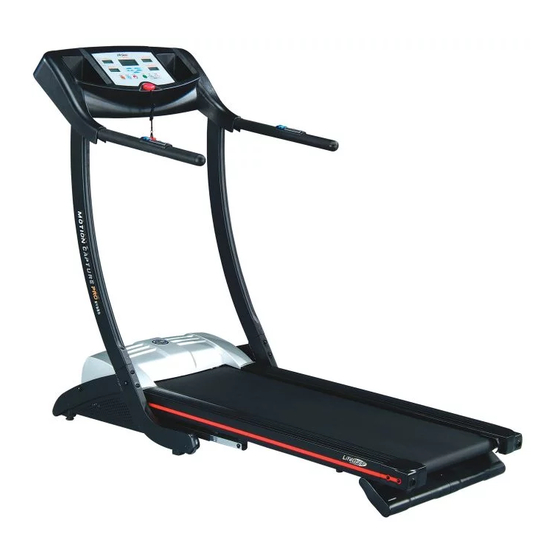
- Page 1 Get active for life MOTION CAPTURE PRO MOTORIZED TREADMILL MODEL# 97930 OWNER'S MANUAL 2006, Feb.
- Page 2 ONE YEAR LIMTED WARRANTY LifeGear Inc. warrants to the original purchaser that this product is free from defects in material and workmanship when used for the purpose intended, under the conditions that it has been installed and operated in accordance with LifeGear's Owner's Manual. LifeGear's obligation under this warranty is limited to replacing or repairing, free of charge, any parts which may prove to be defective under normal home use.
- Page 3 Observe the following prior to use of the treadmill: DANGER: To reduce the risk of electric shock, please observe the following: Always unplug the treadmill from the electrical outlet immediately after using and before cleaning, assembling, or servicing. NOTE: Failure to follow these instructions may lead to personal injury and cause damage to the treadmill. WARNING: To reduce the risk of burns, fire, electric shock please observe the following: Never leave the treadmill unattended when plugged in.
- Page 4 This product must be grounded. If it should malfunction or break down, grounding provides a path of least resistance for electric current reducing the risk of electric shock. * This treadmill is equipped with a cord having equipment grounding connector and a grounding plug. The plug must be plugged into an appropriate outlet that is properly installed and grounded in accordance with all local codes and ordinances.
- Page 6 Part # Description Quantity Part # Description Quantity Main Frame Spacer (Ø 18*Ø 10.5*15.5mm) Stabilizer Deck Bumper End Cap for Stabilizer End Cap ( 25*50) Adjustable Pad (M8) Side Rail (1083mm) Moving Wheel Rear Cap (Right) Running Belt Rear Cap (Left) Running Deck Dust Cover, Upper Front Roller...
- Page 7 Part # Description Quantity Part # Description Quantity Bolt (M8*60mm) Washer (Ø 11*Ø 21*1.8) Screw (M3x10mm) Washer (Ø 8.5*Ø 18*1.5) Hex Socket Button Head Washer (Ø 4.2*Ø 12*0.8) Cap Bolt (M8*40mm) Computer Knob (M5) Nylon Washer (M8) Choke (34MH-40MH) Nylon Nut (M8) Wave Filter (06SS4-2DC1) Bolt (M8*35mm) Wire for Fuse Box (CM-125)
- Page 8 Part # Description Quantity Spring Washer (M8)----------------------------------------------------------------------------------------12 Bolt (M8*16mm) ------------------------------------------------------------------------------------12 Washer (Ø 8.5*Ø 18*1.5)----------------------------------------------------------------------------- 6 Computer Knob (M5) --------------------------------------------------------------------------------4 INCHES PLACE WASHER, BOLT’S END, OR SCREW ON CIRCLE TO CHECK FOR CORRECT SIZE. MILLIMETERS...
-
Page 9: Stabilizer 1
Step 1 Connect the Sensor Cable II (23) from the Right Handlebar Support (37R) to the Sensor Cable III (24) from the Stabilizer (2). Attach the Right and Left Handlebar Supports (37R,37L) to the Stabilizer (2) with six Spring Washers (52) and Bolts (70). Step 2 Connect the Sensor Cable I (22) from the Handlebar (38) to the Sensor Cable II (23) from the Right Handlebar Support (37R). - Page 10 Before beginning a workout session ensure Safety Tether Key is properly installed onto the Computer Console and the Safety Clip is securely attached to an article of your clothing. Always begin the treadmill standing on the side rails-not on the running belt. Allow the treadmill to reach a speed of at least 0.8km before walking on the running belt.
-
Page 11: Incline Beam 1
Fold Up the Treadmill Lift the deck up from the rear of treadmill and fold up until the Spring Knob "pops" down into the locked position. (See diagrams A and B.) Check the Spring Knob is "pop" down into the locked position before moving the treadmill. (See diagram C.) TO PREVENT INJURY PLEASE MAKE SURE YOU HAVE A FIRM HOLD WHEN LIFTING UP OR SETTING DOWN THE DECK. - Page 12 Begin Operation: 1. Install the safety tether key on the computer and then turn on the Master Power that is located at the front of the treadmill. Manual LED is flash and then press the FAST or SLOW button to select P1, P2, P3, P4, P5, or Manual. Press the START button to begin exercise.
-
Page 13: Handlebar
Functions: TIME - None preset time target - Press the START button, time starts counting from 0:00 with each 1 second increment to maximal 99:59 minutes. To preset TIME target in Manual mode when the Manual LED is on - Press the MODE button to select TIME mode when it is flash and then press FAST or SLOW button to preset time target. -
Page 14: Safety Tether Key
Training in Program: There are 5 programs in the computer. Install the safety tether key on the computer and then turn on the Master Power, the Manual LED is flash and then press the FAST or SLOW button to select P1, P2, P3, P4, or P5. P1-P5 Program: Select program function (P1-P5), the training time is preset for 20 minutes, the preset time can not be adjusted by user. -
Page 15: Running Belt Adjustment
Lubrication All the treadmills have been already spread with "Silicone Oil" in advance before the treadmill leaves the factory. Silicone oil is without volatility and has gradually permeated through the running belt. There will be no need to re-spread the oil in normal circumstances. To maintain the running belt, we have included a small bottle of "Silicone Oil". - Page 16 e-mail:sales@lifegear.com.tw...
Need help?
Do you have a question about the 97930 and is the answer not in the manual?
Questions and answers