Table of Contents
Advertisement
Quick Links
��
intelligent motion systems, inc.
Excellence in Motion
TM
IM805
HIGH PERFORMANCE MICROSTEPPING DRIVE
STANDARD DRIVER
CONNECTOR OPTIONS
COOLING SOLUTIONS
ACCESSORIES
OPERATING INSTRUCTIONS
370 N. MAIN ST., PO BOX 457, MARLBOROUGH, CT 06447
PH. (860) 295-6102, FAX (860) 295-6107
Internet: http://www.imshome.com, E-Mail: info@imshome.com
Advertisement
Table of Contents

Related Manuals for Intelligent Motion Systems IM805


Summary of Contents for Intelligent Motion Systems IM805
- Page 1 �� intelligent motion systems, inc. Excellence in Motion IM805 HIGH PERFORMANCE MICROSTEPPING DRIVE STANDARD DRIVER CONNECTOR OPTIONS COOLING SOLUTIONS ACCESSORIES OPERATING INSTRUCTIONS 370 N. MAIN ST., PO BOX 457, MARLBOROUGH, CT 06447 PH. (860) 295-6102, FAX (860) 295-6107 Internet: http://www.imshome.com, E-Mail: info@imshome.com...
- Page 2 Intelligent Motion Systems, Inc.’s general policy does not recommend the use of its products in life support or aircraft applications wherein a failure or malfunction of the product may directly threaten life or injury. Per Intelligent Motion Systems, Inc.’s terms and conditions of sales, the user of Intelligent Motion Systems, Inc., products in life support or aircraft applications assumes all risks of such use and indemnifies Intelligent Motion Systems, Inc., against all damages.
-
Page 3: Table Of Contents
Section Overview ......................24 Selecting a Motor ......................24 Motor Wiring ........................ 29 Connecting the Motor ....................29 Interfacing and Controlling the IM805 ............ 33 Section Overview ......................33 Layout and Interface Guidelines.................. 33 Motor Power Connection (+V) ..................34 Configuring and Controlling the Output Current ............ - Page 4 Cooling Solutions ................... 65 H-4X Heat Sink Kit ...................... 65 Thermal Non-Isolating Pad (TN-48) ................65 Accessories .................... 66 Appendix Overview ..................... 66 U3-CLP: Side-Mounting Clip ..................66 BB-34-4P Breakout Board................... 68 PLG-R Removable Screw Terminal Set..............70 IM805 Operating Instructions Revision R032306...
- Page 5 U3-CLP Mounting Hole Locations ............68 Figure C.2 Attaching the U3-CLP to the IM805 ............69 Figure C.3 Panal Mounting an IM805 Using the U3-CLP Clip Set ......69 Figure C.4 BB-34-4P Breakout Board Mechanical Specifications......70 Figure C.5 BB-34-4P Pin Locations................ 71 Figure C.6...
- Page 6 Table 7.2 Microstep Resolution Switch Settings........... 41 Table 7.3 Recommended Input Current Limiting Resistor Values......43 Table 7.4 Logic Input Timing ................44 Table A.1 IM805-34P1 - Connector P1 Pin Assignment and Description .... 57 IM805 Operating Instructions Revision R032306...
-
Page 7: Introduction
The IM805, because of its small size and low cost, can be used to increase accuracy and smoothness in systems using higher step angle motors. In many instances mechanical gearing can be replaced with microstepping, reducing cost and eliminating potential maintenance. -
Page 8: The Product Manual
T h e P r o d u c t M a n u a l The main sections of this manual address the standard IM805 driver, which come with 8 position screw terminals as a connection medium. The different connector, input options and accessories are covered in detail in the appendices. -
Page 9: Notes And Warnings
WARNING! A current adjustment resistor is always necessary to keep the Driver and/or Motor in a safe operating range. DO NOT operate the IM805 Driver without a current adjustment resistor in place. WARNING! Turn off the AC power side to power down the DC power supply. -
Page 10: Hardware Specifications
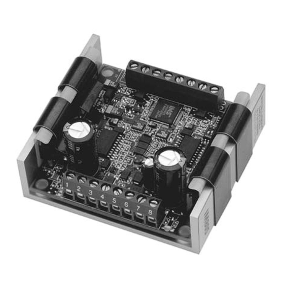
M e c h a n i c a l S p e c i f i c a t i o n s Shown are the standard 8 position screw terminal set and the Optional 34 Pin Connector for the IM805. Specifications for the 34 Pin Connector are available in Appendix A: Standard Connection Options, of this document. -
Page 11: Electrical Specifications
� ������� �������������� ����������������������� �� �� ����������������������� �������������������� ��� � ����������������������� �������������������������� ��� ٠� �������� �� * Includes motor back EMF. **Lower currents may be used for current reduction. Table 2.1: IM805 Electrical Specifications IM805 Operating Instructions Revision R032306... -
Page 12: Thermal Specifications
NOTE! This pin configuration diagram and table represent the pinout of any 8 position connector used for P1. If you purchased the IM805-34P1 option (34 Position Header) the pin configuration diagram and table is located in Appendix A: Standard Connection Options. -
Page 13: Table 2.3 Connector P1 - Pin Assignment And Description
������������������������������������������������������� ����������� Table 2.3: Connector P1 - Pin Assignment and Descriptions WARNING! The IM805 components are sensitive to ElectroStatic Discharge (ESD). All handling should be done at an ESD protected workstation. WARNING! Hazardous voltage levels may be present if using an open frame power supply to power the IM805. -
Page 14: Status Indications
P2 for status indication. When the drive is powered and operating normally, the LED will be green. When in a fault condition, the LED will be red. Figure 2.3: Status Indicator LED 12 IM805 Operating Instructions Revision R032306... -
Page 15: Mounting The Im805
IM805. For additional connector options for the IM805 see Appendix A: Standard Connection Options, of this document. An optional heat sink and thermal pad, the H-4X and TN-48, are available for the IM805. See Appendix C: Cooling Solutions, for details. -
Page 16: Table 3.1 Im805 Mounting Screw/Washer Requirements
WARNING! Use of any mounting hardware other than that recommended may result in damage to the driver circuitry! Use ONLY the hardware recommended by this document to mount the IM805 to your panel or heat sink plate! 14 IM805 Operating Instructions Revision R032306... -
Page 17: Theory Of Operation
T h e o r y o f O p e r a t i o n S e c t i o n O v e r v i e w This section will cover the circuit operation for the IM805 microstepping driver. -
Page 18: Microstep Select (Msel) Inputs
This feature allows the user to switch resolutions at any time without having to keep track of sine/cosine location. Because of this, the On-Full-Step output of the IM805 can easily be used to monitor position. Configuration settings for the Microstep Resolution are located in Section 7 of this document, Interfacing and Controlling the IM805. -
Page 19: Dual Pwm Circuit
In the second part of the cycle the PWM reverts back DRIVE CURRENT to recirculating mode to increase RECIRCULATION efficiency and reduce current Figure 4.3: Non-Recirculating PWM ripple. IM805 Operating Instructions Revision R032306... -
Page 20: Fullstep Output Signal
IM805 will execute the change before taking the next step. Only AFTER the change has been executed will the step be taken. If no change has occurred, the IM805 will simply take the next step. This feature works as an automatic debounce for the direction and microstep resolution select inputs. -
Page 21: Power Supply Requirements
T h e P o w e r S u p p l y - D r i v e r R e l a t i o n s h i p The IM805 is very current efficient as far as the power supply is concerned. -
Page 22: Table 5.1 Motor Power Supply Requirements
��������������������������������� ������������� ����������������������� �������������� �������������� ���� �������������� �������������� ���������������� ������� ���������������������������������������������������������������������� ������������������������������������ Table 5.1: Motor Power Supply Specifications 20 IM805 Operating Instructions Revision R032306... -
Page 23: Table 5.2 +5 Vdc Power Supply Requirements
See the IMS Catalog or web site (http://www.imshome.com) for information on these supplies. Listed below are the power supplies recommended for use with the IM805. I P 8 0 4 / I P 8 0 4 - 2 4 0 †... -
Page 24: Selecting An Opto Supply
Power supply cables must not run parallel to logic level wiring as noise will be coupled onto the logic signals from the power supply cables. If more than one driver is to be connected to the same power supply, run 22 IM805 Operating Instructions Revision R032306... -
Page 25: Ac Line Filtering
Since the output voltage of an unregulated power supply will vary with the AC input applied, it is recommended that an AC line filter be used to prevent damage to the IM805 due to a lightning strike or power surge. WARNING! Verify that the power supply wiring is correct prior to power application. -
Page 26: Motor Requirements
This means it has multiple phases wound in the stator and the rotor is dragged along in synchronism with the rotating magnetic field. The IM805 is designed to work with the following types of stepping motors:... - Page 27 W i n d i n g I n d u c t a n c e Since the IM805 is a constant current source, it is not necessary to use a motor that is rated at the same voltage as the supply voltage. What is important is that the IM805 is set to the motor’s rated current.
- Page 28 Figure 6.1 A & B: Per Phase Winding Inductance The per phase winding inductance specified may be different than the per phase inductance seen by your IM805 driver depending on the wiring configuration used. Your calculations must allow for the actual inductance that the driver will see based upon the wiring configuration.
- Page 29 M-3431-6.3S ............M-3431-6.3D M-3447-6.3S ............M-3447-6.3D IMS also offers 23 and 34 Frame hybrid linear actuators for use with the IM805. Please see the IMS Full Line catalog or the IMS web site at http: //www.imshome.com. IM805 Operating Instructions Revision R032306...
- Page 30 The motor is compatible with IMS bipolar drivers, keeping the system cost low. The IOS motor can operate up to 3000 rpm’s. The IOS motor is available in the following frames: Frame Size IMS PN 23 Frame ..............M3-2220-IOS 34 Frame ..............M3-3424-IOS 28 IM805 Operating Instructions Revision R032306...
-
Page 31: Motor Wiring
The motor leads are connected to the following connector pins: I M 8 0 5 Phase Connector: Pin Phase B ................ P2: 5 Phase B ................ P2: 6 Phase A ................ P2: 7 Phase A ................ P2: 8 IM805 Operating Instructions Revision R032306... -
Page 32: Figure 6.2 8 Lead Motor Series Connections
Multiply the per phase (or unipolar) current rating by 1.96, or the bipolar current rating by 1.4, to determine the peak output current. PHASE A PHASE A PHASE B PHASE B Figure 6.3: 8 Lead Motor Parallel Connections 30 IM805 Operating Instructions Revision R032306... - Page 33 Use the per phase (or unipolar) current rating as the peak output current. PHASE A NO CONNECTION PHASE A PHASE B NO CONNECTION PHASE B Figure 6.5: 6 Lead Full Coil (Higher Torque) Motor Connections IM805 Operating Instructions Revision R032306...
-
Page 34: Figure 6.6 4 Lead Motor Connections
In setting the driver output current, multiply the specified phase current by 1.4 to determine the peak output current. PHASE A PHASE A PHASE B PHASE B Figure 6.6: 4 Lead Motor Connections 32 IM805 Operating Instructions Revision R032306... -
Page 35: Interfacing And Controlling The Im805
I M 8 0 5 S e c t i o n O v e r v i e w This section covers the interface connections, configuration and control signals of the IM805. Covered are: Layout and Interface Guidelines. Motor Power Connection (+V). -
Page 36: Motor Power Connection (+V)
M o t o r P o w e r C o n n e c t i o n ( + V ) Figure 7.1 illustrates the motor power (+V) connection to two IM805 drives using a recommended IMS ISP200-7 unregulated switching power supply. -
Page 37: Configuring And Controlling The Output Current
For any given motor, the output current used for microstepping is deter- mined differently from that of a half/full step driver. In the IM805, a sine/cosine output function is used in rotating the motor. Therefore, when microstepping, the specified phase current of the motor is considered an RMS value. - Page 38 NOTE! The PEAK current will be used to determine the current adjust resistor value, NOT the RMS current! This represents the maximum output current that should be set for your IM805 driver! 4 L e a d M o t o r s Multiply the specified phase current by 1.4 to determine the peak...
- Page 39 S e t t i n g t h e O u t p u t C u r r e n t The IM805 uses an internal 1 milliamp current source to establish the reference voltage needed to control the output current. This voltage is programmed by means of an external 1/8 watt or higher, 1 percent resis- tor connected between P2:2 (Current Adjust) and P2:3 (Power Ground).
-
Page 40: Figure 7.2 Current Adjust Resistor Placement
WARNING! A current adjustment resistor is always necessary to keep the Driver and/or Motor in a safe operating range. DO NOT operate the IM805 Driver without a current adjustment resistor in place. Figure 7.2 illustrates the connection of this resistor. Table 7.1 lists the resistor values for the driver output current in 200 milliamp increments. -
Page 41: Figure 7.3 Current Reduction Adjust Resistor Placement
R e d u c i n g / D i s a b l i n g t h e O u t p u t C u r r e n t The IM805 has the capability of automatically reducing the current in the motor windings following a move. -
Page 42: Controlling The Output Resolution
If remote control of the output resolution is required, these signals are brought out on connector P1 on the IM805-34P1. This option is discussed in detail in Appendix A: Standard Connector Options. SW-1 Figure 7.4: MSEL Switch Showing 50 Microsteps/Step Selected... -
Page 43: Table 7.2 Microstep Resolution Switch Settings
��� �� ��� ������ ��� �� ��� �� �� ������ �� ��� ��� ��� ��� ������ �� ��� ��� ��� �������������������������������������������������������� �� ��� ��� ��� ��� ��� ��� ��� Table 7.2: Microstep Resolution Switch Settings IM805 Operating Instructions Revision R032306... -
Page 44: Interfacing And Using The Isolated Logic Inputs
I n t e r f a c i n g a n d U s i n g t h e I s o l a t e d L o g i c I n p u t s The IM805 has 4 optically isolated logic inputs which are located on connector P1. These inputs are isolated to minimize or eliminate electri- cal noise coupled onto the drive control signals. -
Page 45: Table 7.3 Recommended Input Current Limiting Resistor Values
���� Table 7.3: Recommended Input Current Limiting Resistor Values WARNING! The isolated logic inputs on the IM805 are internally limited to allow for an optocoupler supply voltage of +5 VDC. If using a higher voltage supply, a current limiting resistor must be placed in series with the input or damage will occur to the IM805’s input circuitry, rendering the drive inoperable. -
Page 46: Table 7.4 Logic Input Timing
Please note that the internal sine/cosine position generator will continue to increment or decrement as long as step clock pulses are being received by the IM805. This input is asynchronous to any other input and may be changed at any time. -
Page 47: Figure 7.6 Switch Interface
Open Collector Interface. TTL Interface. We will also show IM805 inputs connected to the IMS LYNX modular mo- tion controller, which is a powerful machine control soulution. S w i t c h I n t e r f a c e A switch connected between the input and the opto supply ground will sink the input. -
Page 48: Figure 7.7 Open Collector Interface
Figure 7.8 shows a TTL device connected to the enable input. This inter- face method may be used with any of the logic inputs. +5 VDC CONTROLLER Opto Supply P1:4 OUTPUT Enable P1:5 Figure 7.8: TTL Interface 46 IM805 Operating Instructions Revision R032306... -
Page 49: Figure 7.9 Lynx Interface
Figure 7.9 shows a LYNX Control Module and Differential I/O Module providing step clock, direction and optocoupler supply voltage to two IM805 drivers. The LYNX isolated I/O may also be used to control the enable and reset inputs, the MSEL inputs (IM805-34P1) and receive feed- back from the fault and fullstep outputs. -
Page 50: Connecting And Using The Fault Output
C o n n e c t i n g a n d U s i n g t h e F a u l t O u t p u t The IM805 has an open collector fault output located on P1:7. This output is non-isolated and has the ability of sustaining maximum driver voltage. -
Page 51: Full Step Output
As noted in the drawing, this is only a representation of a possible application of the full step output. Additional interface circuitry may be required between the IM805 and the counter. Check the documentation provided by the manu- facturer of your counter for interface requirements. -
Page 52: Minimum Connections
IM805. ������� ������� ����������������������������������������������������������������������� ���������� ���� ���������� ���������� �� ��������� �� �� �� � ������������������� ������ ���� ������������������� ������ ������������������ ������������������������ �������� �������������������������������������� ���������������������������� ���� �������������������������������������� ���������������������������� Figure 7.12: IM805 Minimum Required Connections 50 IM805 Operating Instructions Revision R032306... -
Page 53: Troubleshooting
B a s i c T r o u b l e s h o o t i n g In the event that your IM805 doesn’t operate properly, the first step is to identify whether the problem is electrical or mechanical in nature. The next step is to isolate the system component that is causing the prob- lem. - Page 54 Logic wiring next to motor/power wiring. Ground loop in system. Open winding of motor. Phase bad on drive. Invalid microstep resolution select setting. S y m p t o m Motor stalls during acceleration. 52 IM805 Operating Instructions Revision R032306...
- Page 55 S y m p t o m Inadequate holding torque. P o s s i b l e P r o b l e m Incorrect current adjust setting or resistor value. Increase holding current with the current reduction adjust resistor. IM805 Operating Instructions Revision R032306...
-
Page 56: Contacting Technical Support
C o n t a c t i n g Te c h n i c a l S u p p o r t In the event that you are unable to isolate the problem with your IM805, the first action you should take is to contact the distributor from whom you originally purchased your product or IMS Technical Support at 860- 295-6102 or by fax at 860-295-6107. -
Page 57: Standard Connection Options
This connector style would be advantageous in a scenario where the user desiresto plug the IM805 directly into a system PCB. NOTE: When mounting the IM805 directly to a PCB by wire wrap or receptacles, the Heat Sink temperature must still be kept at or below +70°... -
Page 58: Im805-34P1
I M 8 0 5 - 3 4 P 1 The IM805-34P1 connector configuration replaces the 8 position screw terminal at connector location P1 with a 34 pin header. Connector P2 is still an 8 position screw terminal. There are 2 key features that are added with this connector option: Microstep resolution select inputs (MSEL) on P1 allow for remote control of the output resolution. -
Page 59: Table A.1: Im805-34P1 Connector P1Pin Assignment And Description
�������������������������������������������������������� ��������������������������������������������������������� ������������������� �������������������������������������������������������� ������ ������������������������������������������������������ ����������� �� ����������������� �������������������������������������������������� ������������������������������������������������������ �� ���������������� ������������������� �� ������������������������������������ ������������������� �� ������������������������������������ ������������������� �� ������������������������������������ �� ������ ���������������������������������������������� ��������������������������������������������������������������������������������������� ��������������������������������������������������� Table A.1: IM805-34P1 Connector P1Pin Assignment and Description IM805 Operating Instructions Revision R032306... - Page 60 The microstep resolution is synchronized with the step clock input. If the resolution change does not fall on a full step, the IM805 will readjust itself at the next pulse that would overshoot the fullstep position. This feature allows the IM805 to readjust the motor position regardless of the output resolution selected during a resolution change.
-
Page 61: Figure A.3 Msel Connection Using Ttl Interface
���������������������������������������������������� MSEL 0 MSEL 3 Microsteps per Full Step MSEL 1 MSEL 2 ������������������������������������� MSEL 0 MSEL 3 MSEL 1 MSEL 2 Microsteps per Full Step xxxxxxx xxxxxxx Figure A.3: MSEL Connection Using TTL Interface IM805 Operating Instructions Revision R032306... -
Page 62: Figure A.4 Cascading Im805-34P1 Drives Using The Step/Direction Outputs
S t e p C l o c k a n d D i r e c t i o n O u t p u t s Another key feature offered by the IM805-34P1 is the non-isolated step clock and direction outputs. These outputs will follow the step and direction inputs. -
Page 63: Im805-8P2
The P1 connector location uses 8 -0.025 square pins. This connector style is advantageous in a scenario where the user desires to wire wrap the IM805 directly into a system interface or use a receptacle to make the connections. Figures A.5 and A.6 show the pin dimensions. -
Page 64: Im805-34P1-8P2
I M 8 0 5 - 3 4 P 1 - 8 P 2 This option combines the features and potential uses of the IM805-34P1 and the IM805-8P2. The connector pins used for connector P2 are identical to those used on the IM805-8P2. -
Page 65: Im805-Plg
I n t e r f a c i n g t h e A d d i t i o n a l I / O o n C o n n e c t o r P 1 The MSEL inputs and Step/Direction outputs on the IM805-34P1-8P2 are interfaced in the same way as those on the IM805-34P1. See the part of this appendix pertaining to that model of the IM805 for interface and connec- tion details. -
Page 66: Figure A.10 Im805-Plg Pin Location And Orientation
Figure A.10: IM805-PLG Pin Location and Orientation 64 IM805 Operating Instructions Revision R032306... -
Page 67: Cooling Solutions
0.65 W/m-K and a maximum temperature rating of 180°C. One side of the TN-48 pad is adhesive and may be applied directly to the IM805 driver. The TN-48 pad eliminates the problems associated with using thermal grease. This pad are also included in the heat sink kit. -
Page 68: Accessories
U 3 - C L P : S i d e - M o u n t i n g C l i p The U3-CLP mounting clips were specially designed for the IM805, IM483 series of Microstepping drivers and driver indexers and the ISP200 and ISP300 series power supplies to decrease overall panel space and allow for more flexible mounting patterns. -
Page 69: Figure C.2 Attaching The U3-Clp To The Im805
M o u n t i n g The unit should be mounted in Figure C.2: Attaching the U3-CLP to the IM805 accordance with Figure D.3 us- ing the recommended hardware. Ensure that mounting hardware doesn’t interfere with any circuitry... -
Page 70: Bb-34-4P Breakout Board
R e c o m m e n d a t i o n s IMS recommends that the following wiring practices be used to interface to the IM805-34P1 using the BB-34-4P: Wire Size: 16 - 22 AWG Strip Length: 0.200” (5mm) Screw Torque: 3.0 lb-in (0.33 N-m) -
Page 71: Figure C.5 Bb-34-4P Pin Locations
#M3 Flat Washer, Stainless (.05 TH, 6.20 OD) Driver Connector P1 Thermal Pad IMS TN-48 or Equivalent Mounting Screw Torque: 5.0 to 7.0 lb-in (0.60 to 0.80 N-m) Heat Sink Plate Figure C.6: BB-34-4P Mounting Diagram IM805 Operating Instructions Revision R032306... -
Page 72: Plg-R Removable Screw Terminal Set
P1 and P2. Replacement terminals may be ordered individually as needed. The order num- bers for individual replacements are: Connector P1 ............. PLG-R2 Connector P2 ............. PLG-R1 70 IM805 Operating Instructions Revision R032306... - Page 73 Product failure with shipment. Return Product in its original packaging, or packaged so it is protected against electrostatic discharge or physical damage in transit. The RMA number MUST appear on the box or packing slip. Send Product to: Intelligent Motion Systems, Inc., 370 N. Main Street, Marlborough, CT 06447.
- Page 74 Fax: 860/295-6107 Fax: 860/295-6107 Eastern Region Eastern Region Phone: +49/7720/995858-0 Phone: +49/7720/99585 Fareham, Hampshire PO15 5TT © Intelligent Motion Systems, Inc. All Rights Reserved. Fareham, Hampshire PO15 5TT REV120107 E-mail: info@imshome.com E-mail: info@imshome.com Phone: 862/208-9742 Phone: 862/208-9742 IMS Product Disclaimer and most recent product information at www.imshome.com.
Need help?
Do you have a question about the IM805 and is the answer not in the manual?
Questions and answers