Table of Contents
Advertisement
Quick Links
User Guide for Atmel ATA6870 and Atmel ATmega32HVB
Features
®
●
Evaluation of Atmel
ATA6870
●
Monitoring of 12 battery cells
●
Monitoring:
●
Overvoltage (every cell)
●
Undervoltage (every cell)
●
Overheating
●
Overcurrent
●
Open clamp detection
●
12-bit battery cell measurement
●
12-bit temperature measurement
●
Controlling of charge/discharge FETs
●
Status LEDs for easy evaluation
●
Charge balancing
●
Coulomb counting for SOC determination
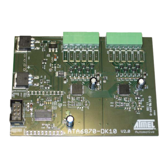
Figure 1.
Atmel ATA6870-DK10
APPLICATION NOTE
Evaluation Kit Hardware
ATA6870-DK10
9228C-AUTO-02/15
Advertisement
Table of Contents

Related Manuals for Atmel ATmega32HVB


Summary of Contents for Atmel ATmega32HVB
-
Page 1: Application Note
APPLICATION NOTE User Guide for Atmel ATA6870 and Atmel ATmega32HVB Evaluation Kit Hardware ATA6870-DK10 Features ® ● Evaluation of Atmel ATA6870 ● Monitoring of 12 battery cells ● Monitoring: ● Overvoltage (every cell) ● Undervoltage (every cell) ● Overheating ●... -
Page 2: Safety Precautions When Using Li-Ion Batteries
12 Cell Battery Management System. The supplied code serves as an example of how to use the Atmel ATMega32HVB and Atmel ATA6870 together. The example is not a complete application intended for use with smart batteries, and it is best to use the devices in a slightly different way in a smart battery application. -
Page 3: System Start
(MBAT) have to be connected. The missing cells should be connected to the upper cell potential of the module. For further information refer to the Atmel ATA6870 datasheet Section 7.3: Reduced Number of Battery Cells Configuration. For the voltage range see Section 3.3 “Powering the Board”... - Page 4 Jumper to enable/disable MISO line of Atmel ATA6870 J9 should never be set while the Atmel ATmega32HVB is being programmed or while it is entering debug mode. It can be mounted as soon as AVR Studio prompts for additional SPI lines to be connected in debug mode or after the device has been correctly programmed.
-
Page 5: Powering The Board
3.3.1 Power Supply The board supports supply voltages from 13.8V (6.9V per Atmel ATA6870) to 60V. However, to run the board on voltages ® below 24V the ZDiode D3 needs to be replaced with a jumper to supply the Atmel ATmega32HVB with sufficient voltage. -
Page 6: Software Description: Monitoring Of Up To 12 Battery Cells
Overheating (the temperature exceeds the upper threshold, default value is 60°C) ● Low temperature threshold (the default threshold is -20°C) LED 3 indicates whether the Atmel ATA6870s are turned on or not. An active LED indicates that the Atmel ATA6870s are enabled. Table 4-1. -
Page 7: Voltage Measurements
The standard software loop measures the voltage ADC value and the offset ADC value for every cell and checks for ® overvoltage and undervoltage once per cycle. Further information about the acquiring of voltages can be found in the Atmel ATA6870 datasheet Section 7.5.1. The formula for calculating the voltage: –... -
Page 8: Temperature Measurements
Frequent reading of the current in a shunt is used to update the SOC frequently. The acquired cell voltages and temperatures can be used to determine the SOC without the Atmel ATmega32HVB. The easiest way is to compare the SOC measured by the added/extracted charge with the calculated SOC using the cell voltage, temperature, and the data provided by the manufacturer of the cells. -
Page 9: Features Of The Atmel Atmega32Hvb
Features of the Atmel ATmega32HVB ® ® Since the Atmel ATmega32HVB is a part of the Atmel AVR family which is dedicated to battery management there are several special features such as coulomb counting and the control of the two charge/discharge MOSFETs. Coulomb Counter The coulomb counter ADC runs on a different clock than the CPU. -
Page 10: Power Consumption
Power Consumption There are several ways to reduce the power consumption of the Atmel ATA6870 and the Atmel ATmega32HVB. Sleep modes are documented in the datasheet of the Atmel ATA6870 Section 7.1.1 and in the Atmel ATmega32HVB datasheet Section 10. This board allows the Atmel ATA6870 to be enabled/disabled using the Atmel ATmega32HVB software. The pin PB2 is used to control a transistor for activating/deactivating the Atmel ATA6870. - Page 11 AVSS ZXMN2F34FH AVDD ATST 1kΩ J4-3 100Ω 100nF ZXMN2F34FH 1kΩ J4-2 100Ω 100nF ZXMN2F34FH 1kΩ J4-1 CELL- 10/0.25WΩ ATMEGA32HVB LED_0603 LED1 1kΩ 2.2μF PA0 (ADC0/SGND/PCINT1) LED2 1kΩ PA1 (ADC1/SGND/PCINT1) 100nF VREG PA2 (PCINT2/T0) LED3 1kΩ VREF PA3 (PCINT3/T1) 100nF VFET...
- Page 12 Figure 7-2. PCB Top ATA6870-DK10 [APPLICATION NOTE] 9228C–AUTO–02/15...
- Page 13 Figure 7-3. PCB Bottom ATA6870-DK10 [APPLICATION NOTE] 9228C–AUTO–02/15...
-
Page 14: Revision History
Revision History Please note that the following page numbers referred to in this section refer to the specific revision mentioned, not to this document. Revision No. History Put document in the latest template 9228C-AUTO-02/15 Section 4.4 “Temperature Measurements” on page 8 updated 9228B-AUTO-10/12 ATA6870-DK10 [APPLICATION NOTE] 9228C–AUTO–02/15... - Page 15 DISCLAIMER: The information in this document is provided in connection with Atmel products. No license, express or implied, by estoppel or otherwise, to any intellectual property right is granted by this document or in connection with the sale of Atmel products. EXCEPT AS SET FORTH IN THE ATMEL TERMS AND CONDITIONS OF SALES LOCATED ON THE ATMEL WEBSITE, ATMEL ASSUMES NO LIABILITY WHATSOEVER AND DISCLAIMS ANY EXPRESS, IMPLIED OR STATUTORY WARRANTY RELATING TO ITS PRODUCTS INCLUDING, BUT NOT LIMITED TO, THE IMPLIED WARRANTY OF MERCHANTABILITY, FITNESS FOR A PARTICULAR PURPOSE, OR NON-INFRINGEMENT.
- Page 16 Mouser Electronics Authorized Distributor Click to View Pricing, Inventory, Delivery & Lifecycle Information: Atmel ATA6870-DK10...
Need help?
Do you have a question about the ATmega32HVB and is the answer not in the manual?
Questions and answers