Table of Contents
Advertisement
Quick Links
AVR 8-bit Microcontrollers
ATmega328PB Xplained Mini
USER GUIDE
Introduction
®
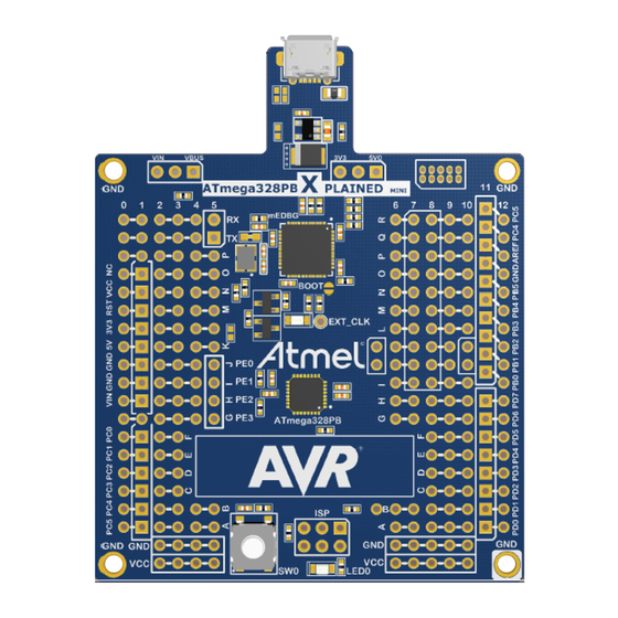
This user guide describes how to get started with the Atmel
ATmega328PB
Xplained Mini board. The ATmega328PB Xplained Mini evaluation kit is a
hardware platform to evaluate the Atmel ATmega328PB microcontroller. The
evaluation kit comes with a fully integrated debugger that provides seamless
integration with Atmel Studio 6.2 (and later version). The kit provides access
to the features of the ATmega328PB enabling easy integration of the device
in a custom design.
Atmel-42469A-ATmega328PB-Xplained-Mini_User Guide-07/2015
Advertisement
Table of Contents

Related Manuals for Atmel ATmega328PB Xplained Mini


Summary of Contents for Atmel ATmega328PB Xplained Mini
-
Page 1: Introduction
This user guide describes how to get started with the Atmel ATmega328PB Xplained Mini board. The ATmega328PB Xplained Mini evaluation kit is a hardware platform to evaluate the Atmel ATmega328PB microcontroller. The evaluation kit comes with a fully integrated debugger that provides seamless integration with Atmel Studio 6.2 (and later version). -
Page 2: Table Of Contents
External Clock....................17 2.5.3. mEDBG COM Port Connection................... 17 2.5.4. mEDBG JTAG Interface....................17 2.5.5. mEDBG USB Interface....................18 2.6. Extension Header Area......................18 2.7. Factory Programmed........................19 2.8. Document Revision History......................20 Atmel ATmega328PB Xplained Mini [USER GUIDE] Atmel-42469A-ATmega328PB-Xplained-Mini_User Guide-07/2015... -
Page 3: Getting Started
- Open Source projects for Xplained Mini. 1.3. Xplained Mini Quick Start How to connect the ATmega328PB Xplained Mini board embedded debugger to Atmel Studio and how to connect the ATmega328PB UART to a COM port. 1.3.1. Connect to Atmel Studio How to connect the ATmega328PB Xplained Mini board embedded debugger to Atmel Studio to get started with SW development. -
Page 4: Connect To The Com Port
ATmega328PB and setting the fuses. Connect the Xplained Mini USB to the PC. Go to Atmel Studio: click the Tools tab, select Device Programming, and select the connected mEDBG as Tool with Device as ATmega328PB and Interface to SPI, click Apply. -
Page 5: Debugging The Target Using Medbg
Click the "Debug" tab and select "Start Debugging and Break". Atmel Studio will display an error message if the DWEN fuse in the ATmega328PB is not enabled, click YES to make Studio set the fuse using the SPI interface. -
Page 6: Programming The Target Using An External Programmer
Connect the External Programmer to the ATmega328PB Xplained Mini board SPI connector. Go to Atmel Studio: click the Tools tab, select Device Programming, and select the External Programmer connected as Tool with Device as ATmega328PB and Interface to SPI, click Apply. -
Page 7: Programming The Atmega32U4 Using A Bootloader
Connect the ATmega328PB Xplained Mini board USB connector to the PC. Select Device = ATmega32U4 (Device - Select). Select USB communication (Ctrl+U). Select memory area to program (use the toggle memory button bellow the Atmel logo). Select Load Hex file (Ctrl+L). Atmel ATmega328PB Xplained Mini [USER GUIDE]... -
Page 8: Board Assembly
1.5.2. Standalone Node The ATmega328PB Xplained Mini board can be used as a standalone node with an external power source, e.g. the 4xAAA or 2xAAA battery pack available from Atmel. 1.5.3. - Page 9 Start Atmel Studio. Connect the Xplained Mini to the computer. In Atmel Studio, select Tools – Device programming (Ctrl – Shift – P) In the Device Programming window, select Tool to mEDBG and click Apply. If there is a new mEDBG version available, the Atmel Studio will ask if you want to upgrade.
- Page 10 Atmel ATmega328PB Xplained Mini [USER GUIDE] Atmel-42469A-ATmega328PB-Xplained-Mini_User Guide-07/2015...
-
Page 11: Hardware User Guide
Hardware User Guide Enter a short description of your concept here (optional). This is the start of your concept. 2.1. Board Overview The ATmega328PB Xplained Mini headers overview. 2.2. Target Headers and Connectors The ATmega328PB related headers. 2.2.1. Target Digital I/O The J200 and J201 headers provide access to the ATmega328PB digital I/O pins. -
Page 12: Board Power Header
ATmega328PB pin Function TXD (ATmega328PB USART Output Pin) RXD (ATmega328PB USART Input Pin) 2.2.2. Board Power Header The J202 header enables connection to the ATmega328PB Xplained Mini power system. Table 2-3 J202 Power Header J202 pin Signal Description VCC_TARGET The power source selected for the target. (Select by J301) -
Page 13: Target Programming
Signals not available in any of the headers or connectors, are available in column 5 of the grid. Table 2-6 Additional I/O ATmega328PB pin Grid position 2.3. Target GUI The ATmega328PB Xplained Mini has One LED, one push button, and a QTouch area. Atmel ATmega328PB Xplained Mini [USER GUIDE] Atmel-42469A-ATmega328PB-Xplained-Mini_User Guide-07/2015... -
Page 14: Push Button
There is one yellow LED, D200, available for use by the application SW. The LED is connected to ATmega328PB pin 17 - PB5 and to the SPI bus SCK signal for, SCK is in 3- state when not used by the mEDBG. Atmel ATmega328PB Xplained Mini [USER GUIDE] Atmel-42469A-ATmega328PB-Xplained-Mini_User Guide-07/2015... -
Page 15: Qtouch Buttons
2.3.3. QTouch buttons Up to 4 QTouch buttons are available on the ATmega328PB Xplained Mini board. The QTouch area can be configured as buttons or as a limited slider. For a typical button or slider reference design use the QT1 Xplained Pro extension. -
Page 16: On-Board Power Supply
100k resistor from PC2 (D1) to the test point in B5.5. 2.4. On-board Power Supply The ATmega328PB Xplained Mini board has an on-board 3.3V regulator (150mA) which can be used to power the ATmega328PB. The J300 and J301 headers configure the ATmega328PB power supply and the board power source. -
Page 17: Medbg External Clock
RxD in to ATmega32U4 2.5.4. mEDBG JTAG Interface The mEDBG (ATmega32U4) JTAG interface is available for programming and debugging of the ATmega32U4. Table 2-11 J100 JTAG Header J100 pin Signal name Description VCC_BOARD ATmega32U4 V Atmel ATmega328PB Xplained Mini [USER GUIDE] Atmel-42469A-ATmega328PB-Xplained-Mini_User Guide-07/2015... -
Page 18: Medbg Usb Interface
The SPI bus signals are made available close to the header at row J and K, enabling easy connection to header pin 15 to 18. Using Pin 11 to 20 enables connection of the 10-pin connector used on the RZ600 wireless modules and the 10-pin Xplained sensor modules. Atmel ATmega328PB Xplained Mini [USER GUIDE] Atmel-42469A-ATmega328PB-Xplained-Mini_User Guide-07/2015... -
Page 19: Factory Programmed
When the CDC COM port is connected to a terminal window (9600 N81), the text you write will be transmitted via the LED in Morse code. Any Morse code transmitted by using the switch will be displayed as text in the terminal window. The ATmega32U4 is preprogrammed with the mEDBG. Atmel ATmega328PB Xplained Mini [USER GUIDE] Atmel-42469A-ATmega328PB-Xplained-Mini_User Guide-07/2015... -
Page 20: Document Revision History
2.8. Document Revision History Document revision Date Comment 42469A 07/2015 Initial document release Atmel ATmega328PB Xplained Mini [USER GUIDE] Atmel-42469A-ATmega328PB-Xplained-Mini_User Guide-07/2015... - Page 21 DISCLAIMER: The information in this document is provided in connection with Atmel products. No license, express or implied, by estoppel or otherwise, to any intellectual property right is granted by this document or in connection with the sale of Atmel products. EXCEPT AS SET FORTH IN THE ATMEL TERMS AND...
Need help?
Do you have a question about the ATmega328PB Xplained Mini and is the answer not in the manual?
Questions and answers