
Subscribe to Our Youtube Channel
Related Manuals for Atmel AT91SAM9RL-EK


Summary of Contents for Atmel AT91SAM9RL-EK
- Page 1 AT91SAM9RL-EK Evaluation Board ........................User Guide 6325A–ATARM–08-Jan-08...
- Page 2 AT91SAM9RL-EK Evaluation Board User Guide 6325A–ATARM–08-Jan-08...
-
Page 3: Table Of Contents
Section 1 Overview ........................1-1 Scope..........................1-1 Deliverables ........................1-1 AT91SAM9RL-EK Evaluation Board.................. 1-1 Section 2 Setting Up the AT91SAM9RL-EK Board ..............2-1 Electrostatic Warning ......................2-1 Requirements........................2-1 Layout ..........................2-2 Powering Up the Board...................... 2-4 Backup Power Supply......................2-4 Getting Started........................ - Page 4 Table of Contents (Continued) Microcontroller Clock ......................4-2 Memory ..........................4-2 Miscellaneous ........................4-2 Section 5 Schematics......................... 5-1 Board Schematics......................5-1 Section 6 Revision History ......................6-1 Revision History ......................... 6-1 AT91SAM9RL-EK Evaluation Board User Guide 6325A–ATARM–08-Jan-08...
-
Page 5: Overview
Section 1 Overview Scope The AT91SAM9RL-EK evaluation kit enables the evaluation of and code development for applications running on an AT91SAM9RL device. It significantly reduces design cycle time, increasing confidence in a right-first-time system solution. This guide focuses on the AT91SAM9RL-EK board as an evaluation platform. - Page 6 Wakeup input push button one reset push button one MCI SD/MMC card slot four expansion connectors (PIOA, PIOB, PIOC, PIOD) one BGA-like EBI expansion footprint connector one Lithium Coin Cell Battery Retainer for 12 mm cell size AT91SAM9RL-EK Evaluation Board User Guide 6325A–ATARM–08-Jan-08...
-
Page 7: Setting Up The At91Sam9Rl-Ek Board
Setting Up the AT91SAM9RL-EK Board Electrostatic Warning Upon delivery, the AT91SAM9RL-EK evaluation board is wrapped in a protective anti-static bag. The board must not be exposed to electrostatic discharges. A grounding strap or similar protective device should be worn when handling the board. Avoid touching the component pins or any other on-board metallic element. -
Page 8: Layout
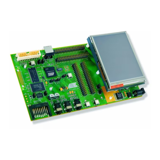
Setting Up the AT91SAM9RL-EK Board Layout Figure 2-1. AT91SAM9RL-EK Layout - Top View AT91SAM9RL-EK Evaluation Board User Guide 6325A–ATARM–08-Jan-08... - Page 9 Setting Up the AT91SAM9RL-EK Board Figure 2-2. AT91SAM9RL-EK Layout - Bottom View AT91SAM9RL-EK Evaluation Board User Guide 6325A–ATARM–08-Jan-08...
-
Page 10: Powering Up The Board
Setting Up the AT91SAM9RL-EK Board Powering Up the Board The AT91SAM9RL-EK requires 5V DC (±5%). DC power is supplied to the board via the 2.1 mm by 5.5 mm socket J1. Coaxial plug center positive standard. Backup Power Supply The user has the possibility to plug a battery (3V Lithium Battery CR1225 or equivalent) in order to per- manently power the backup part of the device. -
Page 11: At91Sam9Rl-Ek Block Diagram
Setting Up the AT91SAM9RL-EK Board AT91SAM9RL-EK Block Diagram Figure 2-3. AT91SAM9RL-EK Block Diagram AT91SAM9RL-EK Evaluation Board User Guide 6325A–ATARM–08-Jan-08... -
Page 12: Board Description
High Speed (480 Mbit/s) USB 2.0 Device Controller – On-Chip High Speed Transceiver, UTMI+ Physical Interface – Integrated FIFOs and Dedicated DMA – 4 Kbyte Configurable Integrated DPRAM Fully-featured System Controller, including – Reset Controller, Shutdown Controller AT91SAM9RL-EK Evaluation Board User Guide 6325A–ATARM–08-Jan-08... - Page 13 – Input Change Interrupt Capability on Each I/O Line – Individually Programmable Open-drain, Pull-up resistor and Synchronous Output 24-channel Peripheral DMA Controller (PDC) One Multimedia Card Interface (MCI) – SDCard/SDIO 1.0 and MultiMedia Card 3.1 Compliant AT91SAM9RL-EK Evaluation Board User Guide 6325A–ATARM–08-Jan-08...
- Page 14 – 1.08 to 1.32V for VDDCORE, VDDPLLB and VDDBU – 3.0V to 3.6V for VDDPLLA, VDDANA, VDDUTMI and VDDIOP – Programmable 1.65V to 1.95V or 3.0V to 3.6V for VDDIOM Available in a 144-ball BGA (AT91SAM9R64) and a 217-ball LFBGA (AT91SAM9RL64) Package AT91SAM9RL-EK Evaluation Board User Guide 6325A–ATARM–08-Jan-08...
-
Page 15: At91Sam9Rl Block Diagram
Atmel serial DataFlash 64 Mbytes of SDRAM memory (32-bit bus width) 256 Mbytes of NAND Flash memory (8-bit bus width) TWI serial EEPROM (footprint only) Clock Circuitry 12 MHz standard crystal for the embedded oscillator AT91SAM9RL-EK Evaluation Board User Guide 6325A–ATARM–08-Jan-08... -
Page 16: Reset Circuitry
One Mono/Stereo Microphone input. 3.11 User Interface Two user input pushbuttons Two user green LED One yellow power LED (can be also software controlled) 3.12 Debug Interface 20-pin JTAG/ICE interface connector DBGU COM port AT91SAM9RL-EK Evaluation Board User Guide 6325A–ATARM–08-Jan-08... -
Page 17: Expansion Slot
Connecting EBI Memory Daughter Boards to AT91SAM Evaluation Boards, lit. 6309. This allows the developer to check the integrity of the components and to extend the features of the board by adding external hardware components or boards. AT91SAM9RL-EK Evaluation Board User Guide 6325A–ATARM–08-Jan-08... -
Page 18: Pio Usage
VDDIOP PA25 MISO DATAFLASH DEVICE MISO VDDIOP PA26 MOSI DATAFLASH DEVICE MOSI VDDIOP PA27 SPCK DATAFLASH DEVICE SPCK VDDIOP PA28 NPCS0 DATAFLASH DEVICE NPCS0 VDDIOP PA29 RTS2 VDDIOP PA30 CTS2 VDDIOP PA31 NWAIT VDDIOP AT91SAM9RL-EK Evaluation Board User Guide 6325A–ATARM–08-Jan-08... - Page 19 SDRAM MEMORY VDDIOM PB24 SDRAM MEMORY VDDIOM PB25 SDRAM MEMORY VDDIOM PB26 SDRAM MEMORY VDDIOM PB27 SDRAM MEMORY VDDIOM PB28 SDRAM MEMORY VDDIOM PB29 SDRAM MEMORY VDDIOM PB30 SDRAM MEMORY VDDIOM PB31 SDRAM MEMORY VDDIOM AT91SAM9RL-EK Evaluation Board User Guide 6325A–ATARM–08-Jan-08...
- Page 20 LCDD16 LCDD22 LCD PANEL LCDD22 VDDIOP PC25 LCDD17 LCDD23 LCD PANEL LCDD23 VDDIOP PC26 LCDD18 VDDIOP PC27 LCDD19 VDDIOP PC28 LCDD20 VDDIOP PC29 LCDD21 TIOA1 VDDIOP PC30 LCDD22 TIOB1 VDDIOP PC31 LCDD23 TCLK1 VDDIOP AT91SAM9RL-EK Evaluation Board User Guide 6325A–ATARM–08-Jan-08...
- Page 21 PD15 or PWM1 VDDIOP PD16 DCD0 PWM2 USER LED 2 PD16 or PWM2 VDDIOP PD17 NAND FLASH MEMORY PD17 as RDYBSY VDDIOP PD18 PWM3 VDDIOP PD19 PCK0 VDDIOP PD20 PCK1 VDDIOP PD21 TCLK2 VDDIOP 3-10 AT91SAM9RL-EK Evaluation Board User Guide 6325A–ATARM–08-Jan-08...
-
Page 22: Jumpers
JTAG/ICE Table 4-2. JTAG/ICE Configuration Designation Default Setting Feature Opened Selects ICE mode or JTAG mode Soldered Enables the ICE NTRST input Soldered Enables the ICE NRST input AT91SAM9RL-EK Evaluation Board User Guide 6325A–ATARM–08-Jan-08... -
Page 23: Microcontroller Clock
USB DEVICE: Enables the use of the USBCNX signal DBGU COM PORT Soldered Enables the use of DTXD output signal Soldered Enables the use of DRXD input RS232 COM PORT: Enable the use of Input/output signals AT91SAM9RL-EK Evaluation Board User Guide 6325A–ATARM–08-Jan-08... - Page 24 Jumpers Table 4-5. Miscellaneous Default Designation Setting Feature Soldered Soldered Soldered Soldered GND Test point GND Test point GND Test point AT91SAM9RL-EK Evaluation Board User Guide 6325A–ATARM–08-Jan-08...
-
Page 25: Schematics
Section 5 Schematics Board Schematics This section contains the following schematics: Board Diagram - Schematic Top Level Power supply AT91SAM9RL Microcontroller EBI Memory Serial Memory Audio AC97 Serial Interface TFT LCD display Expansion connectors AT91SAM9RL-EK Evaluation Board User Guide 6325A–ATARM–08-Jan-08... -
Page 35: Revision History
Section 6 Revision History Revision History Table 6-1. Revision History Document Ref. Comments Change Request Ref. 6325A First issue. AT91SAM9RL-EK Evaluation Board User Guide 6325A–ATARM–08-Jan-08... - Page 36 Disclaimer: The information in this document is provided in connection with Atmel products. No license, express or implied, by estoppel or otherwise, to any intellectual property right is granted by this document or in connection with the sale of Atmel products. EXCEPT AS SET FORTH IN ATMEL’S TERMS AND CONDI- TIONS OF SALE LOCATED ON ATMEL’S WEB SITE, ATMEL ASSUMES NO LIABILITY WHATSOEVER AND DISCLAIMS ANY EXPRESS, IMPLIED OR STATUTORY...
Need help?
Do you have a question about the AT91SAM9RL-EK and is the answer not in the manual?
Questions and answers