
Related Manuals for Atmel AT91SAM7X-EK


Summary of Contents for Atmel AT91SAM7X-EK
- Page 1 AT91SAM7X-EK Evaluation Board for AT91SAM7X and AT91SAM7XC ....................User Guide...
- Page 2 AT91SAM7X-EK Evaluation Board User Guide 6195E–ATARM–22-Mar-07...
-
Page 3: Table Of Contents
3.10 Remote Communication ................3-9 3.11 Analog Interface ..................3-9 3.12 User Interface ...................3-9 3.13 Debug Interface ..................3-10 3.14 Expansion Slot ..................3-10 Section 4 Configuration Straps ................4-1 Configuration Straps .................4-1 Section 5 Schematics ................... 5-1 Schematics ....................5-1 AT91SAM7X-EK Evaluation Board User Guide 6195E–ATARM–22-Mar-07 6195E–ATARM–22-Mar-07... - Page 4 Section 6 Errata ....................6-1 Errata ......................6-1 Section 7 Revision History..................7-1 Revision History ..................7-1 AT91SAM7X-EK Evaluation Board User Guide 6195E–ATARM–22-Mar-07...
-
Page 5: Overview
The AT91SAM7X-EK and the AT91SAM7XC-EK evaluation kits enable evaluation capa- bilities and code development of applications running on the AT91SAM7X or the AT91SAM7XC microcontroller. This guide focuses on the AT91SAM7X-EK board as a common evaluation platform for the AT91SAM7X and AT91SAM7XC devices in a 100-lead LQFP package. Deliverables... - Page 6 Overview ! Power LED and general-purpose LEDs ! DataFlash ® card slot ! expansion connector ! Atmel ® serial DataFlash ! One footprint for Atmel Serial EEPROM (MN11) AT91SAM7X-EK Evaluation Board User Guide 6195E–ATARM–22-Mar-07...
-
Page 7: Setting Up The At91Sam7X-Ek
Avoid touching the component pins or any other metallic element. Requirements In order to set up the AT91SAM7X-EK evaluation board, the following items are required: ! the AT91SAM7X-EK evaluation board itself ! an A/B-type USB cable ! a DC USB power adapter (5V at 0.5 A) with USB A/B cable... -
Page 8: Layout
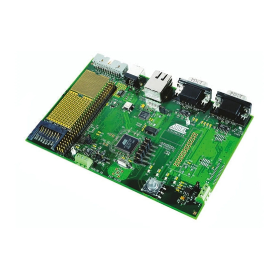
Setting Up the AT91SAM7X-EK Evaluation Board Layout Figure 2-1. Layout - Top View AT91SAM7X-EK Evaluation Board User Guide 6195E–ATARM–22-Mar-07... -
Page 9: Powering Up The Board
Setting Up the AT91SAM7X-EK Evaluation Board Figure 2-2. Layout - Bottom View Powering Up the The AT91SAM7X-EK board is self-powered by the USB port or by a USB power adapter. Board Getting Started The AT91SAM7X-EK evaluation board is delivered with a DVD-ROM containing all nec- essary information and step-by-step procedures for working with the most common development tool chains. -
Page 10: At91Sam7X-Ek Block Diagram
Setting Up the AT91SAM7X-EK Evaluation Board AT91SAM7X-EK Block Diagram Figure 2-3. Block Diagram DATAFLASH CARD READER DBGU USB DEVICE ETHERNET 10/100 RS232 RS232 MDI/MDIX AUTO CROSSOVER VBUS VBUS RJ45 ETHERNET PHY 4 3 2 1 9 NOT POPULATED NRST YELLOW... -
Page 11: Board Description
– Based on Power-on Reset Cells and Low-power Factory-calibrated Brownout Detector – Provides External Reset Signal Shaping and Reset Source Status ! Clock Generator (CKGR) – Low-power RC Oscillator, 3 to 20 MHz On-chip Oscillator and one PLL ! Power Management Controller (PMC) AT91SAM7X-EK Evaluation Board User Guide 6195E–ATARM–22-Mar-07... - Page 12 ! One Synchronous Serial Controller (SSC) – Independent Clock and Frame Sync Signals for Each Receiver and Transmitter – I²S Analog Interface Support, Time Division Multiplex Support – High-speed Continuous Data Stream Capabilities with 32-bit Data Transfer AT91SAM7X-EK Evaluation Board User Guide 6195E–ATARM–22-Mar-07...
- Page 13 – Double PWM Generation, Capture/Waveform Mode, Up/Down Capability ! One Four-channel 16-bit Power Width Modulation Controller (PWMC) ! One Two-wire Interface (TWI) – Master Mode Support Only, All Two-wire Atmel EEPROMs Supported ! One 8-channel 10-bit Analog-to-Digital Converter, Four Channels Multiplexed with Digital I/Os ! SAM-BA ™...
-
Page 14: At91Sam7X Block Diagram
PWM2 SPI0_NPCS0 PWM3 SPI0_NPCS1 SPI0_NPCS2 SPI0 SPI0_NPCS3 SPI0_MISO SPI0_MOSI SPI0_SPCK SPI1_NPCS0 TCLK0 SPI1_NPCS1 Timer Counter TCLK1 SPI1_NPCS2 TCLK2 SPI1 SPI1_NPCS3 TIOA0 SPI1_MISO TIOB0 SPI1_MOSI TIOA1 SPI1_SPCK TIOB1 ADTRG TIOA2 TIOB2 TWCK CANRX CANTX ADVREF AT91SAM7X-EK Evaluation Board User Guide 6195E–ATARM–22-Mar-07... -
Page 15: At91Sam7Xc Microcontroller
! Debug Unit (DBGU) – 2-wire UART and Support for Debug Communication Channel interrupt, Programmable ICE Access Prevention ! Periodic Interval Timer (PIT) – 20-bit Programmable Counter plus 12-bit Interval Counter ! Windowed Watchdog (WDT) AT91SAM7X-EK Evaluation Board User Guide 6195E–ATARM–22-Mar-07... - Page 16 ® – Individual Baud Rate Generator, IrDA Infrared Modulation/Demodulation – Support for ISO7816 T0/T1 Smart Card, Hardware Handshaking, RS485 Support – Full Modem Line Support on USART1 ! Two Master/Slave Serial Peripheral Interfaces (SPI) AT91SAM7X-EK Evaluation Board User Guide 6195E–ATARM–22-Mar-07...
-
Page 17: At91Sam7Xc Export Regulations Statement
– Double PWM Generation, Capture/Waveform Mode, Up/Down Capability ! One Four-channel 16-bit Power Width Modulation Controller (PWMC) ! One Two-wire Interface (TWI) – Master Mode Support Only, All Two-wire Atmel EEPROMs Supported ! One 8-channel 10-bit Analog-to-Digital Converter, Four Channels Multiplexed with Digital I/Os ! SAM-BA ™... -
Page 18: At91Sam7Xc Block Diagram
SPI0_NPCS1 SPI0_NPCS2 SPI0 SPI0_NPCS3 SPI0_MISO SPI0_MOSI SPI0_SPCK SPI1_NPCS0 TCLK0 SPI1_NPCS1 Timer Counter TCLK1 SPI1_NPCS2 TCLK2 SPI1 SPI1_NPCS3 TIOA0 SPI1_MISO TIOB0 SPI1_MOSI TIOA1 SPI1_SPCK TIOB1 ADTRG TIOA2 TIOB2 TWCK CANRX CANTX ADVREF AES 128 TDES AT91SAM7X-EK Evaluation Board User Guide 6195E–ATARM–22-Mar-07... -
Page 19: Memory
! 64 Kbytes of Internal High-speed SRAM ! Atmel serial DataFlash ® ! One footprint for Atmel Serial EEPROM memory. The user can fit an AT24C128AN or AT24C256AN or AT24C512AN in 8S1 package as well as a cryptomemory AT88C25616C-SI ! 18.432 MHz standard crystal for the embedded oscillator... -
Page 20: Debug Interface
! All I/Os of the AT91SAM7X and the AT91SAM7XC are routed to peripheral extension connectors (J16). This allows the developer to check the integrity of the components and to extend the features of the board by adding external hardware components or boards. 3-10 AT91SAM7X-EK Evaluation Board User Guide 6195E–ATARM–22-Mar-07... -
Page 21: Configuration Straps
Enables Ethernet Auto MDIX control. Closed Enables permanent pull up on USB DP. Closed The System Reset signal (NRST) is connected to the ICE/JTAG socket (J7, pin 15). Opened Disables 5V (VUSB) power supply on J16 extension connector. AT91SAM7X-EK Evaluation Board User Guide 6195E–ATARM–22-Mar-07... - Page 22 GND Test point. GND Test point. Note: 1. These jumpers are provided for measuring power consumption. By default, they are closed. To use this feature, the user has to open the strap and insert an anmeter. AT91SAM7X-EK Evaluation Board User Guide 6195E–ATARM–22-Mar-07...
-
Page 23: Schematics
Section 5 Schematics Schematics This section contains the following schematics: ! Processor Board ! I/O ! Ethernet ! RF modules AT91SAM7X-EK Evaluation Board User Guide 6195E–ATARM–22-Mar-07... - Page 24 100K FPS009 FPS009 MODIF. MODIF. MODIF. DES. DES. DES. DATE DATE DATE VER. VER. VER. DATE DATE DATE WRITE PROTECT AT91SAM7X-EK AT91SAM7X-EK AT91SAM7X-EK NOT POPULATED NRST SCALE SCALE SCALE REV. REV. REV. SHEET SHEET SHEET 100NF 100NF AT91SAM7XC-EK AT91SAM7XC-EK AT91SAM7XC-EK...
- Page 25 MODIF. MODIF. MODIF. DES. DES. DES. DATE DATE DATE VER. VER. VER. DATE DATE DATE AT91SAM7X-EK AT91SAM7X-EK AT91SAM7X-EK SCALE SCALE SCALE REV. REV. REV. SHEET SHEET SHEET AT91SAM7XC-EK AT91SAM7XC-EK AT91SAM7XC-EK This agreement is our property. Reproduction and publication without our written authorization shall expose offender to legal proceedings.
- Page 26 13/09/05 13/09/05 13/09/05 MODIF. MODIF. MODIF. DES. DES. DES. DATE DATE DATE VER. VER. VER. DATE DATE DATE AT91SAM7X-EK AT91SAM7X-EK AT91SAM7X-EK SCALE SCALE SCALE REV. REV. REV. SHEET SHEET SHEET AT91SAM7XC-EK AT91SAM7XC-EK AT91SAM7XC-EK ETHERNET ETHERNET ETHERNET This agreement is our property. Reproduction and publication without our written authorization shall expose offender to legal proceedings.
- Page 27 13/09/05 13/09/05 13/09/05 MODIF. MODIF. MODIF. DES. DES. DES. DATE DATE DATE VER. VER. VER. DATE DATE DATE AT91SAM7X-EK AT91SAM7X-EK AT91SAM7X-EK SCALE SCALE SCALE REV. REV. REV. SHEET SHEET SHEET AT91SAM7XC-EK AT91SAM7XC-EK AT91SAM7XC-EK RF MODULES RF MODULES RF MODULES This agreement is our property. Reproduction and publication without our written authorization shall expose offender to legal proceedings.
- Page 28 Schematics AT91SAM7X-EK Evaluation Board User Guide 6195E–ATARM–22-Mar-07...
-
Page 29: Errata
R39 should be replaced by smaller values (e.g., 2.2 KΩ). for Fast Mode operation Note that there is no need to change the pull-up resistors if the TWI is used in Standard Mode (up to 100 Kbits/s). AT91SAM7X-EK Evaluation Board User Guide 6195E–ATARM–22-Mar-07... - Page 30 Errata AT91SAM7X-EK Evaluation Board User Guide 6195E–ATARM–22-Mar-07...
-
Page 31: Revision History
Removed references to 32 Mbit serial DataFlash (AT45DB321C-CNC) in 2862 Section 3.6 Figure 2-3 Section 5 and in . Inserted new and new schematics in Section 6.2 ”TWI line pullups for Fast Mode operation” 6195E Added Errata 4084 AT91SAM7X-EK Evaluation Board User Guide 6195E–ATARM–22-Mar-07... - Page 32 Revision History AT91SAM7X-EK Evaluation Board User Guide 6195E–ATARM–22-Mar-07...
- Page 33 Disclaimer: The information in this document is provided in connection with Atmel products. No license, express or implied, by estoppel or otherwise, to any intellectual property right is granted by this document or in connection with the sale of Atmel products. EXCEPT AS SET FORTH IN ATMEL’S TERMS AND CONDI- TIONS OF SALE LOCATED ON ATMEL’S WEB SITE, ATMEL ASSUMES NO LIABILITY WHATSOEVER AND DISCLAIMS ANY EXPRESS, IMPLIED OR STATUTORY...
Need help?
Do you have a question about the AT91SAM7X-EK and is the answer not in the manual?
Questions and answers