
Related Manuals for Atmel AT89STK-11


Summary of Contents for Atmel AT89STK-11
- Page 1 AT89STK-11 Starter Kit ....................Hardware User Guide...
-
Page 2: Table Of Contents
Batchisp Software ...................3-13 Section 4 Appendix A: Board Layout ..............4-14 Appendix B: Bill of Materials ............... 4-15 Bill of Materials Table................4-15 Appendix C: Board Schematics ............4-17 Appendix D: References/Acronyms ............ 4-22 References....................4-22 Acronyms ....................4-22 AT89STK-11 Hardware User Guide 7676B–8051–08/07... -
Page 3: Introduction
Section 1 Introduction This document describes the AT89STK-11 board dedicated to the standard C51 micro- controllers with in-system programming. All of the microcontroller I/Os are made available in an expansion area with prototyping facilities. Features Stand-alone Board In-System Programmable (ISP) including ‘Auto ISP’ feature... -
Page 4: Supported Devices
Introduction Supported AT89C51RE2 Devices AT89C51RB2 AT89C51RC2/IC2 AT89C51RD2/ID2/ED2 AT89STK-11 Hardware User Guide 7676B–8051–08/07... -
Page 5: Hardware Description
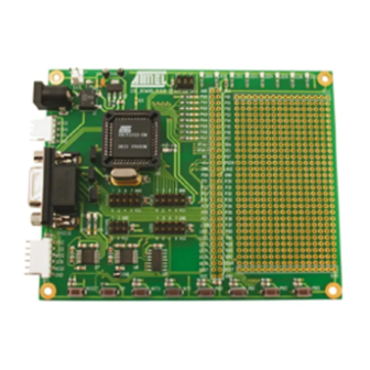
Section 2 Hardware Description Board Overview Figure 2-1 shows the AT89STK-11 board. Figure 2-1. AT89STK-11 This photo is not contractual and may be modified without notification by Atmel. AT89STK-11 Hardware User Guide 7676B–8051–08/07... -
Page 6: Block Diagram
Hardware Description Block Diagram Figure 2-2 shows the functional block diagram of the AT89STK-11, with the I/O usage. Figure 2-2. Block Diagram of AT89STK-11 PC Host Full UART 16MHz Quartz Expansion Area PLCC44 INT0 INT1 Leds: User LEDs User Push Buttons... -
Page 7: Reset
Note: Keep SP1 closed when using the EXT input Reset To be compatible with Atmel microcontrollers which have (or not) its on-chip RESET cir- cuitry (c.f.microcontroller datasheet), the board provides a RESET signal witch can come from 2 different sources: 2.4.1... -
Page 8: Features
The signals sda and scl are controlled by the TWI ports of MCU. This TWI bus is also connected to the expansion area. External TWI pull-ups are not provided on the AT89STK-11. 2.6.2 The SPI connector is directly connected to SPI I/O of the MCU. -
Page 9: Board Settings
Hardware Description This interface enables the debug of the application through ATMEL OCD dongle for AT89C51RE2/IE2/RD3/IE3 only. 2.6.5 Expansion Area In addition to a 16x29 pad array, two rows of pads are given on the right side of the board to offer all the MCU signals tu user application. Any application expansion can be built on board through this interface. - Page 10 2.7.3 Test Points Test points are used to check the internal power supply of the microcontroller. Table 2-3. Table of Test Points Reference PCB Label Function Test point for Vcc TP2,TP3 Test point for GND AT89STK-11 Hardware User Guide 7676B–8051–08/07...
-
Page 11: Isp Programming
ISP mode. Auto ISP Mode It allows the host PC application (Atmel Flip software for example) to control the hard- ware conditions from the serial lines RTS and DTR. Thus with the Auto ISP mode, the user does not need to push the ISP and RESET buttons. -
Page 12: Flip Software
Operating Systems. FLIP supports in-sys- tem programming of Flash C51 devices through RS232. The latest version of FLIP software can be downloaded from the Atmel web site, www.atmel.com. Batchisp Batchisp is an In-System Programming application which can perform the same opera- Software tions as FLIP but is designed to be launched from the DOS command window. -
Page 13: Appendix A: Board Layout
Section 4 Appendix A: Board Layout Figure 4-1. Board Components View Diagram AT89STK-11 Hardware User Guide 4-12 7676B–8051–08/07... -
Page 14: Appendix B: Bill Of Materials
1 R3 1/16W-5% SMD Case 0603 Multicomp 8 R4,R6,R8,R9,R10,R11,R12, 0.06W, 5% Case 0603 Multicomp SP1,SP2,SP3,SP4,SP5, SP6, SP7, SP8, SP9, SP10, SP11, SolderPad SP12 8 SW1,SW2,SW3,SW4,SW5,SW6, ® PUSH-BUTTON SMD, rectangular See DS ITT Canon SW7,SW8 AT89STK-11 Hardware User Guide 4-13 7676B–8051–08/07... - Page 15 2 U7,U8 SIPEX-SP3232ECA Ref=SP3232ECA SSOP16 Maxim 1 U9 74HC125/SO SOIC texas 1 Y1 CRYSTAL HC49 28bis 2 Y1 CRYSTAL tulip R100, R101, R102, R103, 4,7K 0.06W, 5% Case 0603 Multicomp R104, R105, R106, R107 AT89STK-11 Hardware User Guide 4-14 7676B–8051–08/07...
-
Page 16: Appendix C: Board Schematics
Appendix C: Board Schematics AT89STK-11 Hardware User Guide 4-15 7676B–8051–08/07... - Page 17 Appendix C: Board Schematics Figure 4-2. AT89STK-11 Schematics (1 of 4) AT89STK-11 Hardware User Guide 4-16 7676B–8051–08/07...
- Page 18 Appendix C: Board Schematics Figure 4-3. AT89STK-11 Schematics (2 of 4) 4-17 AT89STK-11 Hardware User Guide 7676B–8051–08/07...
- Page 19 Appendix C: Board Schematics Figure 4-4. AT89STK-11 Schematics (3 of 4) AT89STK-11 Hardware User Guide 4-18 7676B–8051–08/07...
- Page 20 Appendix C: Board Schematics Figure 4-5. AT89STK-11 Schematics (4 of 4) 4-19 AT89STK-11 Hardware User Guide 7676B–8051–08/07...
-
Page 21: Appendix D: References/Acronyms
Appendix D: References/Acronyms References AT89C51RD2/ID2/ED2/RB2/RC2/IC2/RE2/IE2 and AT89C51RD3/IE3 Product Datasheet. Acronyms FLIP: FLexible In-system Programming ISP: In-System programming AT89STK-11 Hardware User Guide 4-20 7676B–8051–08/07... -
Page 22: Acronyms
4. Appendix A, page 4-13 : the given board layout was wrong. Replaced by the right one. 5. Appendix C, page 4-19 : there was an error on page 4 of the schematic. Pin5 of U9B is now connected to Vcc instead of GND. 4-21 AT89STK-11 Hardware User Guide 7676B–8051–08/07... - Page 23 Disclaimer: The information in this document is provided in connection with Atmel products. No license, express or implied, by estoppel or otherwise, to any intellectual property right is granted by this document or in connection with the sale of Atmel products. EXCEPT AS SET FORTH IN ATMEL’S TERMS AND CONDI- TIONS OF SALE LOCATED ON ATMEL’S WEB SITE, ATMEL ASSUMES NO LIABILITY WHATSOEVER AND DISCLAIMS ANY EXPRESS, IMPLIED OR STATUTORY...
- Page 24 Mouser Electronics Authorized Distributor Click to View Pricing, Inventory, Delivery & Lifecycle Information: Atmel AT89STK-11...
Need help?
Do you have a question about the AT89STK-11 and is the answer not in the manual?
Questions and answers