Table of Contents
Advertisement
Quick Links
Atmel AVR UC3 32-bit Microcontrollers
UC3L Evaluation Kit
USER GUIDE
Introduction
®
The Atmel
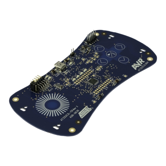
AT32UC3L-EK is an evaluation kit and development system for
®
the Atmel AVR
UC3 AT32UC3L064 microcontroller.
®
As an evaluation kit, the board focus is towards Atmel QTouch
and
™
®
QMatrix
support, and Atmel picoPower
technology.
As a development system, the board notably provides on-board memory, a
USB communication interface, an accelerometer, and the JTAG
programming and debugging interface. The AT32UC3L-EK also features
expansion headers; one of these is the wireless expansion header (named
WLESS on the PCB), which is the receptacle for one of the two RZ600 radio
boards provided in the kit package.
Atmel-32150C-UC3L-EK_User Guide-06/2015
Advertisement
Table of Contents

Subscribe to Our Youtube Channel
Related Manuals for Atmel AT32UC3L-EK


Summary of Contents for Atmel AT32UC3L-EK
-
Page 1: Introduction
The Atmel AT32UC3L-EK is an evaluation kit and development system for ® the Atmel AVR UC3 AT32UC3L064 microcontroller. ® As an evaluation kit, the board focus is towards Atmel QTouch ™ ® QMatrix support, and Atmel picoPower technology. As a development system, the board notably provides on-board memory, a USB communication interface, an accelerometer, and the JTAG programming and debugging interface. -
Page 2: Table Of Contents
UC3L-specific Information................... 21 2.6.4. Configuration and Test Points..................23 2.7. USB Interface..........................23 2.7.1. Overview........................24 2.7.2. Schematics........................26 2.7.3. UC3L-specific Information................... 26 2.7.4. Configuration and Test Points..................26 2.8. AT32UC3L064..........................27 2.8.1. Overview........................27 2.8.2. Schematics........................28 Atmel UC3L Evaluation Kit [USER GUIDE] Atmel-32150C-UC3L-EK_User Guide-06/2015... - Page 3 2.8.3. AT32UC3L064 Pinout....................28 2.8.4. Configuration and Test Points..................30 3. UC3L-EK Schematics....................31 4. Errata and Troubleshooting..................32 5. Evaluation Board/kit Important Notice..............33 6. Revision History.......................34 Atmel UC3L Evaluation Kit [USER GUIDE] Atmel-32150C-UC3L-EK_User Guide-06/2015...
-
Page 4: Kit Overview
Kit Overview This chapter lists the features provided by the AT32UC3L-EK evaluation kit and describes the content of the box the kit is packaged in. Figure 1-1 AT32UC3L-EK Block Diagram User Interface External Memory CAT & SPI0 Touch ACIFB DataFlash GPIO LEDs (LED0..3) -
Page 5: Features
1.1. Features The following is a list of the main components and interfaces on the AT32UC3L-EK: • Main MCU: Atmel AVR UC3 32-bit AT32UC3L064 (TQFP48) – 64KB internal flash, 16KB internal RAM – Up to 50MHz operation – Very low power consumption –... -
Page 6: Power-Up And Getting Started
Reference Materials The AVR UC3 L0 series datasheet The AT32UC3L-EK Schematics AVR32777: AT32UC3L-EK Getting Started Guide The 32-bit AVR UC3 L series Schematic Checklist The AVR Software Framework All pre-loaded firmware source code is available in the AVR Software Framework version 2.0 or higher. -
Page 7: Hardware Description
• All possible hardware configurations of the block and available test points 2.1. Power Supply The power supply block of the AT32UC3L-EK is in charge of distributing power to all components of the board. 2.1.1. Overview Figure 2-1 AT32UC3L-EK Power Supply Logical View The AT32UC3L-EK can be powered from three different sources: the USB Mini-AB plug (5V input), an external power supply connected to the J2 header (DC 5V ±... -
Page 8: Schematics
To customize the hardware configuration of this block, see Section Configurations and Test Points page 9, for a description of the possible hardware configurations of the power supply block. Figure 2-2 AT32UC3L-EK Top View Power Supply Location Figure 2-3 AT32UC3L-EK Bottom View Power Supply Location 2.1.2. -
Page 9: Configurations And Test Points
AT32UC3L-EK schematics package. 2.1.4.2. Test Points A few test points covering the power supply block have been placed on the AT32UC3L-EK for the verification of important signals. Table 2-2 Power Supply Block Test Points Designation Feature Input voltage level after D1 when the J2 external power supply is used Input voltage for all boards' components except the AT32UC3L064. -
Page 10: Power Consumption Measurement
To measure the power consumption on the AT32UC3L064 VDDIN, remove the 0Ω R19 resistor and measure the current over the J6 2-pin header (not mounted by default). Figure 2-4 AT32UC3L-EK Power Consumption Measurement Headers Location The above figure points to the location of the power consumption measurement area. To accurately locate... -
Page 11: User Interface
2.2. User Interface Figure 2-5 AT32UC3L-EK User Interface Logical View User Interface CAT& Touch ACIFB GPIO LEDs AT32UC3L064 (LED0..3) User Interface GPIO PushButton (Wake) ADCIFB 3-axis PushButton Accelerometer (RST) The main user interface offered by the kit is the touch user interface consisting of the wheel sensor and the five button sensors. -
Page 12: User Interface Schematics
Figure 2-6 AT32UC3L-EK Top View User Interface Location Figure 2-7 AT32UC3L-EK Bottom View User Interface Location 2.2.1. User Interface Schematics In the Schematic document, the components of the user interface are found: • On page 1 for the RST pushbutton • On page 3 for the three-axis accelerometer •... -
Page 13: Hardware Configuration And Test Points
This was done to support the aWire programming and debugging interface (refer to Section Programming and Debug Interface on page 14). To enable the hardware debounce support on the RST pushbutton, mount the 0Ω R36 resistor (solder patch). Atmel UC3L Evaluation Kit [USER GUIDE] Atmel-32150C-UC3L-EK_User Guide-06/2015... -
Page 14: Programming And Debug Interface
AT32UC3L-EK schematics package. 2.2.3.2. Test Points A few test points covering the user interface block have been placed on the AT32UC3L-EK for the verification of important signals. Table 2-6 User Interface Block Test Points Designation Feature Input voltage on the AT32UC3L064 RESET_N pin, depending on the state of the RST... -
Page 15: Schematics
The main programming and debugging interface of the AT32UC3L-EK is meant to program and debug the AT32UC3L064. There are two debug interfaces available on the AT32UC3L064: the JTAG interface and the aWire interface (single pin debug system), both accessible through the J9 connector. - Page 16 JTAG lines while debugging. Conflict conditions over the debugging pins, highlights the components on the AT32UC3L-EK that might interfere with the multiplexed JTAG pins. These components must not be used while debugging with the JTAG interface.
-
Page 17: External Memory
Figure 2-10 AT32UC3L-EK External Memory Logical View External Memory SPI0 AT32UC3L064 DataFlash The AT32UC3L-EK contains a 64Mbit Atmel DataFlash device (AT45DB642D-CNU) that is connected to the SPI0 interface of the AT32UC3L064. Figure 2-11 AT32UC3L-EK External Memory Logical View 2.4.2. Schematics In the Schematics document, the external memory is described on page 3. -
Page 18: Uc3L-Specific Information
J44.2-4 and/or with a jumper on J44.1-3. 2.4.4.2. Test Points Two test points covering the Atmel DataFlash have been placed on the AT32UC3LEK for the verification of important signals. Table 2-12 Atmel Dataflash Test Points Designation... -
Page 19: Real Time Clock
32kHz crystal input PA20 N.A. XOUT32_2 32kHz crystal output 2.5.2. Test Points Two test points covering the RTC block have been placed on the AT32UC3L-EK for the verification of important signals. Table 2-14 RTC Block Test Points Designation Feature 32kHz crystal output... -
Page 20: Overview
There are two expansion headers on the AT32UC3L-EK: • The J8 header (labeled WLESS on the PCB) connects the Atmel RZ600 AT86RF231 radio board to provide wireless communication capabilities to the kit. Signals on J8.1 and J8.2 are configurable with the J44 header. The AT32UC3L064 modules available on J8 are USART1 and SPI0. -
Page 21: Schematics
On page 7 for the J14 and J15 headers 2.6.3. UC3L-specific Information 2.6.3.1. Atmel AT32UC3L064 Pinouts for the Expansion Headers Table 2-15 UC3L Pinouts for the J8 and J44 Headers QFP48 pin GPIO GPIO Alternate Functions Feature PA00 USART1.RTS or GPIO[0] Provides access to the USART1.RTS signal or to the RZ600.RST feature. - Page 22 Software-dependent J15.7 PA22 Software-dependent J15.9 PB00 Software-dependent J15.11 PB01 Software-dependent J15.13 PB02 Software-dependent J15.15 PB03 Software-dependent J15.17 GND on J15.19 VCC3 on J15.2 PB04 Software-dependent J15.4 PB05 Software-dependent J15.6 PB06 Software-dependent J15.8 Atmel UC3L Evaluation Kit [USER GUIDE] Atmel-32150C-UC3L-EK_User Guide-06/2015...
-
Page 23: Configuration And Test Points
2.7. USB Interface The USB interface on the AT32UC3L-EK offers USB communication capabilities to the AT32UC3L064 through the on-board AT32UC3B1256 device. Atmel UC3L Evaluation Kit [USER GUIDE]... -
Page 24: Overview
LEDs (D12&D13) Configuration Interface GPIO Jumper (J12) The USB interface provides two features to the AT32UC3L-EK kit: • USB communication • Power supply (see Section Power Supply on page 7 for a description of that feature) The USB controller is the AT32UC3B1256. - Page 25 Programming the AT32UC3B1256 will overwrite the default firmware. The AT32UC3B256 can be programmed and debugged through the JTAG interface J13 header. The AT32UC3B1256 is connected to the AT32UC3L064's USART3 TX and RX pins. Figure 2-16 AT32UC3L-EK Top View USB Interface Location Atmel UC3L Evaluation Kit [USER GUIDE] Atmel-32150C-UC3L-EK_User Guide-06/2015...
-
Page 26: Schematics
Otherwise, the USB HID QTouch Debug firmware will execute. 2.7.4.2. Test Points A few test points covering the USB interface block have been placed on the AT32UC3L-EK for the verification of important signals. Atmel UC3L Evaluation Kit [USER GUIDE]... -
Page 27: At32Uc3L064
Section Programming and Debug Interface on page 14. The AT32UC3L064 has access to one external on-board Atmel DataFlash 64Mb memory. For a detailed presentation of the external memory block, see Section External Memory on page 17. -
Page 28: Schematics
AT32UC3B1256 device, pre-loaded with several default firmware components providing added features to the kit. For a detailed presentation of the USB interface block, see Section USB Interface on page 23. Figure 2-18 AT32UC3L-EK Top View AT32UC3L064 Location 2.8.2. Schematics In the Schematics document, the AT32UC3L064 is described on page 1. - Page 29 TOUCH_SMP PA18 ADCIFB[4] VBAT PA19 CAT.CSA[10] TOUCH_X10 PA20 XOUT32_2 PA21 GPIO[21]/TC0.B1/PWMA[21]/ LED_0 SCIF.GCLK0 PA22 CAT.CSB[10] TOUCH_X11 PB00 USART3.TXD USBGW_UC3L_TX PB01 USART3.RXD USBGW_UC3L_RX PB02 GPIO[34]/TC0.A2/PWMA[25]/ LED_2 SCIF.GCLK1 PB03 GPIO[35]/TC0.B2/PWMA[26]/TC1.A2 LED_3 PB04 CAT.CSA[14] TOUCH_X14 Atmel UC3L Evaluation Kit [USER GUIDE] Atmel-32150C-UC3L-EK_User Guide-06/2015...
-
Page 30: Configuration And Test Points
A few test points covering the AT32UC3L064 have been placed on the AT32UC3LEK for the verification of important signals. Table 2-21 AT32UC3L064 Test Points Designation Feature GNDANA VDDANA To locate the test points mentioned here above, use the assembly top/bottom views provided within the AT32UC3L-EK schematics package. Atmel UC3L Evaluation Kit [USER GUIDE] Atmel-32150C-UC3L-EK_User Guide-06/2015... -
Page 31: Uc3L-Ek Schematics
UC3L-EK Schematics Schematics (AT32UC3L-EK schematics package) are available on the Atmel website www.atmel.com. Atmel UC3L Evaluation Kit [USER GUIDE] Atmel-32150C-UC3L-EK_User Guide-06/2015... -
Page 32: Errata And Troubleshooting
The pin-through holes near the touch sensors may cause spurious touch events. On some AT32UC3L-EK kits, the pin-through holes are not protected, causing spurious touch events when the fingers are not exactly on the touch sensors. -
Page 33: Evaluation Board/Kit Important Notice
(WEEE), FCC, CE or UL (except as may be otherwise noted on the board/kit). Atmel supplied this board/kit "AS IS," without any warranties, with all faults, at the buyer's and further users' sole risk. The user assumes all responsibility and liability for proper and safe handling of the goods. -
Page 34: Revision History
Revision History Doc. Rev Date Comments 32150C 06/2015 New template and some minor corrections 32150B 03/2012 32150A 08/2010 Initial document release Atmel UC3L Evaluation Kit [USER GUIDE] Atmel-32150C-UC3L-EK_User Guide-06/2015... - Page 35 DISCLAIMER: The information in this document is provided in connection with Atmel products. No license, express or implied, by estoppel or otherwise, to any intellectual property right is granted by this document or in connection with the sale of Atmel products. EXCEPT AS SET FORTH IN THE ATMEL TERMS AND...
- Page 36 Mouser Electronics Authorized Distributor Click to View Pricing, Inventory, Delivery & Lifecycle Information: Microchip AT32UC3L-EK...
Need help?
Do you have a question about the AT32UC3L-EK and is the answer not in the manual?
Questions and answers