Atmel AT90USB162 User Manual
Enhanced development board
Hide thumbs
Also See for AT90USB162:
- User manual (14 pages) ,
- Specification sheet (4 pages) ,
- Quick manual (2 pages)

Related Manuals for Atmel AT90USB162


Summary of Contents for Atmel AT90USB162
- Page 1 DBAT90USB162 ® Atmel AT90USB162 Enhanced Development Board User’s manual DBAT90USB162 Enhanced Development Board User’s Manual embeddedglow.com...
- Page 2 Its design provides configurability and flexibility not available with other products. The board provides all the basic circuitry needed to work with AT90USB162: USB connector and circuit, crystal and clock configuration circuitry, Reset and HWB buttons, status LED, user button and LED, power source/voltage configuration circuitry, configurable voltage regulator, isolation resistors to combine ISP lines with other functions.
- Page 3 Optional transient voltage suppression for USB data lines; Reset (RST) button; ® Hardware boot (HWB) button – allows forcing bootloader (stock Atmel or third- party) execution at reset (see AT90USB82/AT90USB162 datasheet) – allows MCU programming via USB without external programmer. I/O pin is still useable for other purposes;...
-
Page 4: Specifications
As all MCU I/O pins are accessible and all MCU powering and clocking options are available the SBAT90USB162a is compatible with virtually every project and development tool designed for AT90USB162 and particularly for AVR MCUs. DBAT90USB162 Enhanced Development Board User’s Manual... - Page 5 1.5. MCU OVERVIEW The AT90USB162 is a low-power CMOS 8-bit microcontroller based on the AVR enhanced RISC architecture. By executing powerful instructions in a single clock cycle, the AT90USB162 achieves throughputs approaching 1 MIPS per MHz allowing optimization of power consumption versus processing speed.
- Page 6 – Master/Slave SPI Serial Interface – Programmable Watchdog Timer with Separate On-chip Oscillator – On-chip Analog Comparator – Interrupt and Wake-up on Pin Change On Chip Debug Interface (debugWIRE) Special Microcontroller Features – Power-On Reset and Programmable Brown-out Detection –...
- Page 7 1.5.2. Block diagram DBAT90USB162 Enhanced Development Board User’s Manual embeddedglow.com...
-
Page 8: Demo Program
1.5.3. Memory map 1.6. DEMO PROGRAM The DBAT90USB162 comes with a simple demo program installed. It makes LED1 blink, while pressing BUT1 changes the blinking rate. This program doesn’t provide USB compatibility. AVR-GCC source file is available for download at http://embeddedglow.com/products/DBAT90USB162/DBAT90USB162_Demo.c. - Page 9 2.1. SCHEMATIC DBAT90USB162 Enhanced Development Board User’s Manual embeddedglow.com...
- Page 10 2.2.3. HWB button (S1) The hardware boot button allows forcing bootloader execution after reset (see AT90USB162 datasheet) thus allowing MCU programming via USB without external programmer. The HWB mode is active only when the HWBE fuse is enabled. In that case PD7/HWB pin is configured as input during reset and sampled during reset rising edge.
- Page 11 Programming via USB is based on pre-programmed USB bootloader, located in the on-chip boot section of the AT90USB162. This is the easiest and fastest way to reprogram the device directly over the USB interface, but with certain limitations. To force bootloader execution, operate as follows: ...
- Page 12 Header Note: 1. Type B and Mini USB connectors cannot be used simultaneously. 2. New, unprogrammed AT90USB162 device is seen via USB as “AT90USB162 DFU”. To use USB driver installation is required. USB drivers can be downloaded from Atmel’s site: http://atmel.com/*. Third- party drivers are also available on the net.
- Page 13 VCC presence, no matter what the power source is, is indicated by the green VCC ON LED (D5). 2.2.7. Built-in voltage regulator The built-in voltage regulator depending on J5 produces 3.3 V or 5 V from a source, connected to PWR1 (P7) or PWR2 (P8). Based on LM1117, the voltage regulator can deliver up to 0.8 A from 5.2 V to 20 V input.
- Page 14 The JTAG connector is intended for use with devices like JTAGICE mkII and AVR ONE!, but only offers in-circuit programming and debugging via debugWIRE as the full JTAG interface is not supported by AT90USB162. The JTAG 10-pin connector pinout is different from ISP 10-pin connector pinout,...
- Page 15 2.2.11. MCU headers (P17..P20) Provide support for optional header boards for MCU allowing the use of several (differently programmed) MCUs. 2.2.12. R13..R16 isolation resistors Provide isolation for SCK, MISO, MOSI, and HWB pins, if they have to be used for other purposes (not recommended).
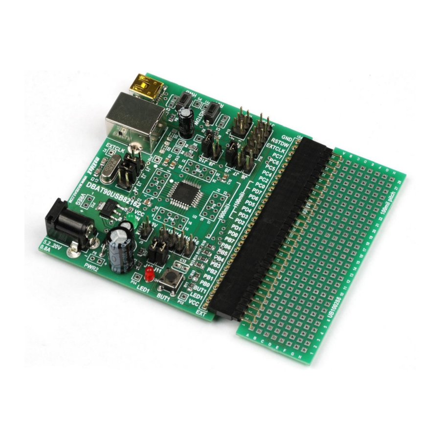
- Page 16 2.2.13. Extension header (P21) Provides connection to other devices and circuitry allowing access to all MCU I/O pins, power supply, and most other signals. Fits any 100mil/2.54mm linear connector, thus providing connectivity with virtually any 100mil/2.54mm universal or breadboard. Example 1: Use male/female headers and connect universal board like UB100288 or any third-party universal or breadboard.
-
Page 17: Board Layout And Dimensions
3. BOARD LAYOUT AND DIMENSIONS DBAT90USB162 Optional UB100288 □ DBAT90USB162 Enhanced Development Board User’s Manual embeddedglow.com... - Page 18 All rights are reserved. ® ® Atmel logo and combinations thereof, and AVR are registered trademarks or trademarks of Atmel Corporation or its subsidiaries. ® Windows is a registered trademark of Microsoft Corporation. *As this document provides links to web pages and/or resources, the inclusion of those links is for reader's convenience only, and should not be interpreted as an endorsement of the owner/sponsor of the site or the content of the site.
Need help?
Do you have a question about the AT90USB162 and is the answer not in the manual?
Questions and answers