Table of Contents
Advertisement
Quick Links
User Guide for the Evaluation Kit ATA8510-EK1
Features
•
User guide for the ATA8510-EK1 evaluation kit
•
Demonstrates an application with the
–
RF transceiver Atmel
Xplained PRO SAMD20 kit
–
Atmel ATA8510 RF transceiver remote sensor with an
AT30TS75A temperature sensor and an optional CMM-1923
real-time clock
–
Two-way RF communication
•
New software version of the SAMD20 base station V2.0 is without
FreeRTOS
Description
This user guide describes an evaluation kit for industrial RF applications
having the following components:
•
A base station using an
–
Xplained PRO SAMD20 evaluation kit
–
Xplained PRO OLED1 extension board
–
Xplained PRO ATA8510/15 extension board
•
Remote temperature sensor with Atmel
application
The Atmel ATA8515 is used as an RF transceiver in the base station and
runs in polling mode to detect data telegrams and displays the received
message on the OLED. The received message is also streamed to a PC
terminal program using a virtual COM port connection.
The remote sensor includes an AT30TS75A temperature sensor device and
a CMM-1923 real-time-clock device for waking up the Atmel ATA8515 RF
transceiver. The Flash application reads the temperature data from the
sensor device using a TWI bus protocol implemented in software and
broadcasts the temperature data via the RF link.
The RF application uses a 2-way communication, i.e., the transmitted RF
telegrams are acknowledged from the receiver.
APPLICATION NOTE
®
ATA8515 in a base station with an
®
ATA8510 running a Flash
Atmel-9343D-ATAN0046_Application Note-09/2016
ATAN0046
Advertisement
Table of Contents

Related Manuals for Atmel ATA8510-EK1


Summary of Contents for Atmel ATA8510-EK1
-
Page 1: Features
ATA8510 running a Flash application The Atmel ATA8515 is used as an RF transceiver in the base station and runs in polling mode to detect data telegrams and displays the received message on the OLED. The received message is also streamed to a PC terminal program using a virtual COM port connection. -
Page 2: References
[3] C-MAX CMM-1923-V1.0 datasheet http://www.atmel.com http://www.iar.com [6] Atmel ATAN0096 - ATA8510 Programmers Guide [7] Atmel ATAN0035 - ATA583x and ATA578x Configuration Tool Guide and software [8] Atmel ATAN0036 - ATA583x and ATA578x Flash Application Development [9] Atmel ATA8510/ATA8515 User Manual [10] ATA8510-EK1_Tool_Pack_V2.0.zip... -
Page 3: Table Of Contents
Table of Contents Features.......................... 1 Description........................1 References........................2 1. Getting Started......................4 1.1. Kit Setup............................4 1.2. Upgrade Kit V1.x to V2.0 ......................6 2. Data Protocol and Signal Timing................7 2.1. Data Protocol for Remote Sensor Telegram.................7 2.2. Data Protocol for Base Station Acknowledge................8 2.3. -
Page 4: Getting Started
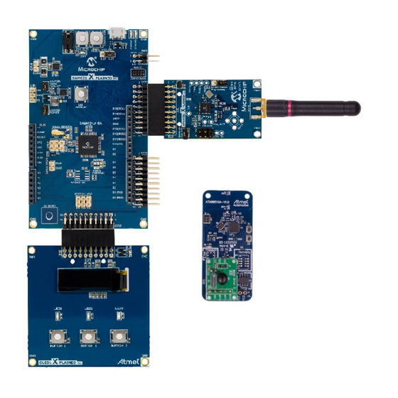
Xplained PRO SAMD20 board. The USB cable can be connected to a 5V/500mA USB power supply for stand-alone operation. When using the virtual COM port, the USB cable is connected to Atmel User Guide for the Evaluation Kit ATA8510-EK1 [APPLICATION NOTE] Atmel-9343D-ATAN0046_Application Note-09/2016... - Page 5 PC's USB port, which requires previous installation of Atmel Studio 6 or 7 IDE [4]. This installation includes all required USB drivers for operation of the Xplained PRO SAMD20 board. Figure 1-2. ATA8510-EK1 Kit Atmel Studio 6 or 7 can be downloaded from [4] with additional user instructions and tools.
-
Page 6: Upgrade Kit V1.X To V2.0
® Any Atmel ATA8510-EK1 kit can operate with V2.0 tool pack by programming the SAMD20 base station with the application software from tool pack V2.0 [10]. The remote sensor need no update and will operate with V1.x and V2.0 base station applications (see section Xplained PRO SAMD20 Base Station for more details). -
Page 7: Data Protocol And Signal Timing
ID for RSSI data Data payload Integer RSSI value [0-255] Checksum Checksum of ID and data payload as 2th complement Total Data telegram with Ttx = 11ms at 8kBit/s Atmel User Guide for the Evaluation Kit ATA8510-EK1 [APPLICATION NOTE] Atmel-9343D-ATAN0046_Application Note-09/2016... -
Page 8: Data Protocol For Base Station Acknowledge
The base station reads the acknowledgement frame with the RSSI data (RX2), displays the result and switches into polling mode again. Figure 2-1. Signal Timing Remote sensor 1.5ms 11ms 5.5ms Base polling Atmel User Guide for the Evaluation Kit ATA8510-EK1 [APPLICATION NOTE] Atmel-9343D-ATAN0046_Application Note-09/2016... -
Page 9: Hardware Description
® board are available within Atmel Studio 6 or 7 on the Atmel website [4]. The hardware description of the Xplained PRO ATA8510/15 extension board and the remote sensor are included in the tool pack zip folder [10]. The base station is powered by the USB cable whereas the remote sensor uses a CR2032 coin cell battery. -
Page 10: Remote Sensor Transceiver
RF data telegram. The mini ISP header is used for Flash and EEPROM programming and for Flash application debugging of the Atmel ATA8510 (see [8] for more details about Flash application development). - Page 11 11ms at a power level of 6dBm, resulting in current consumption of about 9.4mA. In OFF mode the temperature sensor is switched off and the resulting current is indicated by the Atmel ATA8510 transceiver and the CMM-1923 RTC current consumption. This OFF mode current is highly dependent on ambient temperature shown in the datasheets [1] and [3].
- Page 12 Mean Current Battery Lifetime (Days/Years) (mA) CR2032 (230mAh) CR2450 (560mAh) Days Years Days Years 0.053 0.022 1083 0.011 2131 0.006 1696 4130 11.3 0.002 3880 10.6 9448 25.9 Atmel User Guide for the Evaluation Kit ATA8510-EK1 [APPLICATION NOTE] Atmel-9343D-ATAN0046_Application Note-09/2016...
-
Page 13: Software Description
The following section describes each program flow. The IAR embedded workbench for AVR [5] is used together with the JTAGICE3 debug tool for Flash application development of the remote sensor. Atmel Studio 6 or 7 [4] is used together with the debug tool included on the Xplained PRO SAMD20 board for SAMD20 application development. -
Page 14: Base Station Application For Samd20 Mcu
Show RF settings pressed? Send Acknowledge Button 2 Show COM port settings pressed? Wait for Sensor answer Display temperature and Button 3 Show RF statistics pressed? RSSI data Atmel User Guide for the Evaluation Kit ATA8510-EK1 [APPLICATION NOTE] Atmel-9343D-ATAN0046_Application Note-09/2016... - Page 15 This message is shown when the received data telegram is corrupted or when the temperature sensor is broken or not present. !!!!!!!!!!!!!!!!!!!!!! Sensor error: Invalid sensor data! !!!!!!!!!!!!!!!!!!!!!! Atmel User Guide for the Evaluation Kit ATA8510-EK1 [APPLICATION NOTE] Atmel-9343D-ATAN0046_Application Note-09/2016...
-
Page 16: Software Development
Studio 6 or 7 the USB driver will be installed automatically when connecting the Xplained Pro SAMD20 board for the first time. When opening Atmel Studio you will see the landing page of this kit were you can obtain the documentation and sample projects. The OLED display will show the welcome screen and wait for a RF telegram from the remote sensor. - Page 17 Additional documentation regarding the other ASF functions can be obtained within Atmel Studio 6 or 7 Help. Figure 4-3. Base Software The debugging of the application is performed within Atmel Studio 6 or 7 together with the Xplained PRO SAMD20 board. This board includes an embedded debugger which is controlled by Atmel Studio. 4.3.2.
- Page 18 Debugging of the application is currently not supported within IAR Embedded Workbench using the AVR debug tool JTAGICE3. Atmel Studio 6 or 7 has to be used instead. Once the program is compiled and linked within IAR Workbench, the file fwFLASH.d90 has to be opened within Atmel Studio 6 or 7 as...
- Page 19 Atmel ATA8510 device is provided in [6] and [8]. This application note describes development for the Atmel ATA5831 device which, in terms of Flash development, is similar to the Atmel ATA8510 device.
-
Page 20: Eeprom Data Settings
Atmel ATA5831 device has to be selected instead of the Atmel ATA8510 or ATA8515 within the programming dialog of Atmel Studio 6. Make sure that the ISP signals are available for the programmer only and that the device is not in OFF mode by pulling an NPWRONx pin to GND level, i.e., connect the PC1 pin to GND. -
Page 21: Revision History
• Chapter 4: text changed • Chapter 4.2: completely changed • Chapter 4.3: text changed • Chapter 4.3.1: completely changed • Chapter 4.3.2: text changed • Chapter 4.3.3: text changed Atmel User Guide for the Evaluation Kit ATA8510-EK1 [APPLICATION NOTE] Atmel-9343D-ATAN0046_Application Note-09/2016... - Page 22 DISCLAIMER: The information in this document is provided in connection with Atmel products. No license, express or implied, by estoppel or otherwise, to any intellectual property right is granted by this document or in connection with the sale of Atmel products. EXCEPT AS SET FORTH IN THE ATMEL TERMS AND...
Need help?
Do you have a question about the ATA8510-EK1 and is the answer not in the manual?
Questions and answers