Summary of Contents for Atmel AT89C5131A
- Page 1 AT89C5131A Starter Kit ....................Hardware User Guide...
-
Page 2: Table Of Contents
Feature Description...................2-6 External Connectors .................2-8 Section 3 Device Programming ................3-9 In-System Programming ................3-9 Using a Programmer .................3-9 Section 4 Appendix..................... 4-11 Electrical Schematics ................4-12 Component Placement ................4-16 Mechanical Outlines................4-17 Bill of Materials..................4-17 AT89C5131A Starter Kit Hardware User User Guide 4245A–USB–11/04... -
Page 3: Introduction
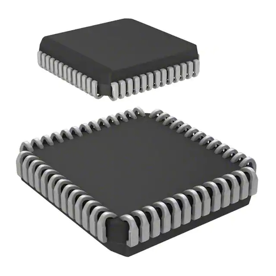
Section 1 Introduction This document describes the AT89C5131A Starter Kit Evaluation Board dedicated to the AT89C5131A USB microcontroller. This board is designed to allow an easy evalua- tion of the product using demonstration software (refer to Software Guide). Features The AT89C5131A evaluation board provides the following features: Possibility to choose between two packages for the AT89C5131A –... - Page 4 Introduction Figure 1-1. AT89C5131A Evaluation Board AT89C5131A Starter Kit Hardware User Guide 4245A–USB–11/04...
-
Page 5: Hardware Description
Hardware Description Section 2 Hardware Description Block Diagram Figure 2-1. AT89C5131A Evaluation Board Components Device Power Supply Device Reset AT89C5131A Host, INT0 RS232 Device... Programming C51 Generic Board Interface Interface Specific Device Human C51 Generic Board AT89C5131A Starter Kit Hardware User Guide... -
Page 6: Power Supply
Power VBUS VBUS and External Source Current Limiter Regulation PWR.S. PWR.S. PWR.S. Direct Input 3.3V 3.3V 3.3V PWR.S. PWR.S. PWR.S. 5V Regulate 3.3V 3.3V 3.3V PWR.S. PWR.S. PWR.S. 3.3V Regulate 3.3V 3.3V 3.3V AT89C5131A Starter Kit Hardware User Guide 4245A–USB–11/04... -
Page 7: C51 Standard Settings
Figure 2-3. EA Circuitry 2.3.4 INT0 In order to use the on-board INT0 circuitry, connect the J7 Jumper to the AT89C5131A. When you press the INT0 button (SW5), the P3.2 pin will go low which induces an inter- rupt event. -
Page 8: Feature Description
Hardware Description Feature Description 2.4.1 RS232 The AT89C5131A evaluation board includes all the required hardware to manage the RS232 communication. Figure 2-5. RS232 On-board Circuitry 2.4.2 USB Peripheral The AT89C5131A evaluation board provides all the required hardware to develop a USB firmware for the AT89C5131A, this includes: –... - Page 9 – P3.5 (LED 1) – P3.6 (LED 2) – P3.7 (LED 3) The on board LEDs can be controlled with the AT89C5131A if the corresponding con- tacts CT9, CT10, CT11 and CT12 are bypassed. Figure 2-6. On-board LEDs for LED Controller...
-
Page 10: External Connectors
P3.7 - RD P1.1 - KBD 1 P2.7 P1.2 - KBD 2 P4.0 P1.3 - KBD 3 P4.1 P1.4 - KBD 4 P1.5 - KBD 5 P1.6 - KBD 6 BUZZER P1.7 - KBD 7 AT89C5131A Starter Kit Hardware User Guide 4245A–USB–11/04... -
Page 11: Device Programming
Section 3 Device Programming In-System The user memory of the AT89C5131A part can be programmed using the ISP mode of the device. In order to enter in ISP mode, first select the high pin count mode (PSEN) or Programming the low pin count mode (P1.0) using the ISP switch (SW2). -
Page 12: Appendix
Section 4 Appendix AT89C5131A Starter Kit Hardware User Guide 4-11 Rev. 4245A–USB–11/04... -
Page 13: Electrical Schematics
Appendix Electrical Schematics Electrical Schematics 4-12 AT89C5131A Starter Kit Hardware User Guide 4245A–USB–11/04... - Page 14 Appendix AT89C5131A Starter Kit Hardware User Guide 4-13 4245A–USB–11/04...
- Page 15 Appendix 4-16 AT89C5131A Starter Kit Hardware User Guide 4245A–USB–11/04...
- Page 16 Appendix AT89C5131A Starter Kit Hardware User Guide 4-17 4245A–USB–11/04...
- Page 17 Appendix 4-18 AT89C5131A Starter Kit Hardware User Guide 4245A–USB–11/04...
-
Page 18: Component Placement
AT89C5131A Evab 1.0.2 PWR.S. D+ D- 3.3V CRYSTAL UNLOAD POWER LPC TEST MODE Figure 4-2. AT89C5131A Evaluation Board Component Implementation 1 2 3 4 5 1 2 3 TP1 TP2 CT10 CT11 CT12 CT13 AT89C5131A Starter Kit Hardware User Guide 4-19 4245A–USB–11/04... -
Page 19: Mechanical Outlines
Appendix Mechanical Figure 4-3. AT89C5131A Evaluation Board Mechanical Outlines Outlines 99.06 mm 2.54 mm 5.08 mm Top view 93.98 mm (37*2.54 mm) C51 Generic Board’s C51 Generic Board’s Left connector Right connector 2.54 mm BOTTOM Bill of Materials Table 4-1. Bill of Materials... - Page 20 CONTACT CT4, CT5, CT6, CT7, CT8, CT9, CT10, CT11, CT12, CT13, CT14 10 µF TANTAL 1N4002 A16_Buzz Jumper Limiter Jumper Power Source Jumper Regulator Jumper Level jumper 121-1% 365-1% 196-1% CONTACT BREAKER AT89C5131A Starter Kit Hardware User Guide 4-21 4245A–USB–11/04...
- Page 21 Appendix Table 4-1. Bill of Materials (Continued) Reference Part SW3, SW4, SW5 PUSH-BUTTON MAX708SCSA TPS2041AD LM1084/TO263 CRYSTAL AT89C5131A Starter Kit Hardware User Guide 4-22 4245A–USB–11/04...
- Page 22 No licenses to patents or other intellectual property of Atmel are granted by the Company in connection with the sale of Atmel products, expressly or by implication. Atmel’s products are not authorized for use as critical components in life support devices or systems.
- Page 23 Mouser Electronics Authorized Distributor Click to View Pricing, Inventory, Delivery & Lifecycle Information: Atmel AT89STK-05...


Need help?
Do you have a question about the AT89C5131A and is the answer not in the manual?
Questions and answers