Advertisement
Quick Links
Download this manual
See also:
Manual
1 Product Name
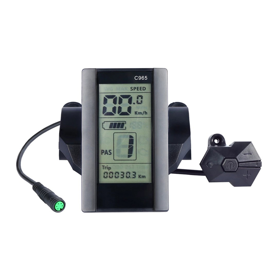
1.1 The Middle install intelligent LCD Display
1.2 Model:C965
2 Suppliers
RisunMotor-Suzhou Bafang
3 Electrical Parameters
24V/36V/48V battery supply
Rated operating current : 10mA
Max operating current : 30mA
Off leakage current < 1uA
Max output current to controller : 50mA
Operating temperature : -30~70℃
Storage temperature : -40~70℃
4 Dimensions & Material
4.1 Product shell is ABS, transparent window is made with high strength Acrylic, the
stiffness equals the tempered glass.
4.2 Dimensions : host/L90mm*W54mm*H13.3mm
Advertisement

Related Manuals for BAFANG C965


Summary of Contents for BAFANG C965
- Page 1 1 Product Name 1.1 The Middle install intelligent LCD Display 1.2 Model:C965 2 Suppliers RisunMotor-Suzhou Bafang 3 Electrical Parameters 24V/36V/48V battery supply Rated operating current : 10mA Max operating current : 30mA Off leakage current < 1uA Max output current to controller : 50mA Operating temperature : -30~70℃...
- Page 2 5 Features Suitable for low temperature,Max -30℃. Ergonomic external button design, easy to operate. Speed display : AVG SPEED, MAX SPEED, SPEED(Real-time). Kilometer / Mile : Can be set according to customers’ habits. Smart battery indicator : Provide a reliable battery indicator, it will not fluctuate with the motor on/off.
-
Page 3: Lcd Instructions
Mileage indicator : Odometer/Trip distance/ Riding time Error code indicator Parameter settings : Multiple parameter can be set through computer USB port, including Assist level / Wheel diameter / Voltage / Speed limit… 6 LCD instructions The figure of LCD display see below: Speed mode Speed display Battery indicator... - Page 4 automatically shut down when there is no operate & ride for X minutes(X could be 0~9). 7.2 Assist level operating Short press UP/DOWN button can change the assist level. Top assist level is 9, 0 for neutral. Level quantities can be adjusted according to the customer requirements. Assist operating 7.3 Speed mode switch&...
-
Page 5: Parameter Setting
7.5 6km walk Press and hold DOWN button for 1 second can get into walk mode, out of the mode when release the button. 7.6 Data cleanup Press and hold UP & DOWN buttons together for 1 second can reset several temporary data, temporary data include AVG Speed / MAX Speed / Trip / Time. - Page 6 Backlight Kilometer/Mile Auto off time Wheel diameter Brightness Speed limit set Password Voltage set 8.1 Kilometer / Mile : The location of speed displays symbol S7, press UP/DOWN button rotate display the symbol km/h / MPH (Km / Mile) 8.2 .Backlight brightness : The location of speed displays symbol bL1, press UP/DOWN button display symbol 1~5 to change the brightness of the backlight.
- Page 7 8.4 Wheel diameter : The location of speed displays symbol Wd, press UP/DOWN button rotate display the symbol 16/18/20/22/24/26/700C/28/29, value represents the diameter of the wheel (inch). Wrong value for wheel diameter will cause speed&mileage abnormal. 8.5 .Voltage set : The location of speed displays symbol bU0, press UP/DOWN button rotate display the symbol 24V/36V/UbE, UbE means user-defined voltage setting, this parameter can be set through computer.
- Page 8 8.7 Speed limit set : The location of speed displays symbol SPL, the location of mileage displays speed limit value, the default value is 25km/h. Press UP/DOWN buttons to modify the value, the value can be set from 10 to 45km/h. Press POWER button to confirm when you finish the adjustment.
-
Page 9: Assembly Instructions
10 Assembly instructions Please pay attention to the screw’s torque value, damaged caused by excessive torque is not within the scope of the warranty. There are 2 directions for the clamp installation, forward or backward. Different assembly methods will need different cable length. - Page 10 Clamps suit for 3 size of handlebar, 31.8mm, 25.4mm, 22.2mm, there are transfer rings for 25.4mm and 22.2mm, transfer ring must be assembled with the special directions, pay attention to the green arrow below. 11 Warning There is waterproof membrane inside the sound hole. Don’t insert sharp object into the hole, it will causes waterproof failure.
- Page 11 1、 Red wire : Anode(24v/36v) 2、 Blue wire : Power cord to the controller 3、 Black wire : 4、 Green wire : RxD (controller -> display) Yellow wire : TxD (display -> controller) 5、 13 Assist level instructions Assist level can be customized, the highest level is 9, common used assist level see the table below: 3 level 5 level...