
Related Manuals for BAFANG CR A101.C 1.0


Summary of Contents for BAFANG CR A101.C 1.0
- Page 1 10 DEALER MANUAL FOR CR A101.C 1.0 CONTENT 10.1 Introduction 10.3 Cabling Connection 10.2 Product Description 10.3.1 Connect the battery 10.2.1 Outline and geometric size 10.3.2 Connect the motor 10.2.2 Interface definition 10.3.3 Connect the EB-BUS 10.2.3 Specification 10.3.4 Connect the sensor 10.2.4 Function overview...
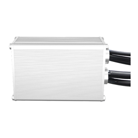
- Page 2 • Identification: Note: Content in the label is important information about this product. Please do not remove the information from the controller. • Model: CR A101.C 1.0 • Scope: EN 15194 EPAC 10.2 PRODUCT DESCRIPTION 10.2.1 Outline and geometric size...
- Page 3 10.2.2 Interface definition Name Schematic diagram Description Power + Battery Black Power - Thick yellow Phase V Thick green Phase U Thick blue Phase W White Speed hall Motor M9.1 Black Green Hall U Yellow Hall V Blue Hall W 1 Yellow CAN L 2 Red...
- Page 4 Name Schematic diagram Description Green CAN H Brown Power assist 1 Torque sen- Black sor cable White CAN L M6.5 Purple Power assist 2 Orange Headlight signal Headlight cable Black White/Black Taillight signal Taillight cable Black Blue Throttle signal Yellow CAN L White Brake signal...
- Page 5 10.2.3 Specification 10.2.4 Function overview • Power Supply: 36V DC • Communication protocol: CAN • Rated Input Power: 350W • Brake cut-off function • Rated Output Power: 250W • Power assist type: torque and speed • Rated Current: 10A • Battery communication function •...
- Page 6 10.3.3 Connect the EB-BUS Please connect the connectors from the control- ler and EB-BUS cable together. E. The female connector from the EB-BUS cable e. The male connector from the controller 10.3.4 Connect the sensor Please connect the connectors from the control- ler and the sensor together.
Need help?
Do you have a question about the CR A101.C 1.0 and is the answer not in the manual?
Questions and answers