
Related Manuals for Siemens 7MF4333


Summary of Contents for Siemens 7MF4333
- Page 1 USER'S MANUAL Siemens Industry, Inc. UMSITRPDS3-1 Rev 10 November 2010 Supersedes Rev 9 SITRANS P, Series DSIII Transmitters Pressure, Differential Pressure, Flanged Level, and Absolute Pressure Model 7MF4*33-...
- Page 2 Designation 7MF4033 Figure 9-1 Table 9-1 Table 9-2 Absolute or Gauge 7MF4233 Figure 9-2 Table 9-3 Table 9-4 Pressure 7MF4333 Figure 9-3 Table 9-5 Table 9-6 Differential 7MF4433 Table 9-7 Figure 9-3 or 9-4 Table 9-9 Pressure 7MF4533 Table 9-8...
-
Page 3: Table Of Contents
UMSITRPDS3-1 Contents TABLE OF CONTENTS Section and Title Page Conventions, Symbols, and General Information..............viii Conventions and Symbols ....................viii Scope ..........................viii Warranty ..........................ix Qualified Persons ......................... ix General Warnings and Cautions................... ix 1.0 INTRODUCTION....................1-1 1.1 CONTENTS........................1-1 1.2 PRODUCT DESCRIPTION ....................1-2 1.3 RATING, APPROVAL, AND TAG PLATES..............1-9 1.4 CONFIGURATION ......................1-9 1.5 CUSTOMER/PRODUCT SUPPORT................1-10... - Page 4 Contents UMSITRPDS3-1 4.3.1 Mechanical ........................4-2 4.3.2 Electrical ........................4-3 4.3.3 Impulse Piping for Absolute and Differential Models ..........4-4 4.3.4 Transmitter Operating Mode and Network Type............4-10 4.3.5 Power Supply Requirements ...................4-14 4.3.6 Determining Network (Loop) Length................4-17 4.3.7 Network Junctions ....................4-19 4.3.8 Safety Barriers ......................4-19 4.3.9 Connection of Miscellaneous Hardware ..............4-20 4.3.10 Shielding and Grounding ..................4-21 4.4 MECHANICAL INSTALLATION ..................4-22...
- Page 5 UMSITRPDS3-1 Contents 6.2.11 Select the Displayed Input Pressure Engineering Unit ..........6-16 6.3 LOCAL OPERATION WITHOUT A DISPLAY OR WITH ACTIVATED KEYLOCK..6-18 6.3.1 Set Zero and Full Scale ...................6-18 6.4 REMOTE CONFIGURATION AND OPERATION BY HART..........6-20 6.4.1 Process Data ......................6-20 6.4.2 Setting Zero and Full Scale ..................6-21 6.4.3 Blind Setting of Zero and Full Scale ................6-21 6.4.4 Zero Adjustment for Position Correction..............6-21 6.4.5 Electric Damping......................6-22...
- Page 6 9.0 MODEL DESIGNATIONS AND SPECIFICATIONS ..........9-1 9.1 MODEL 7MF4033, GAGE PRESSURE ................9-2 9.2 MODEL 7MF4233, ABSOLUTE PRESSURE..............9-7 9.3 MODEL 7MF4333, ABSOLUTE PRESSURE..............9-12 9.4 MODELS 7MF4433 AND 7MF4533, DIFFERENTIAL PRESSURE AND FLOW ...9-17 9.5 MODELS 7MF4633 AND 7MF4812, LEVEL ..............9-24 9.6 SERVICE PARTS, ALL MODELS ..................9-30...
- Page 7 8-6 Absolute Pressure Measuring Cell, Gauge Construction ...........8-5 9-1 Model 7MF4033, Dimensions .....................9-2 9-2 Model 7MF4233, Dimensions .....................9-7 9-3 Models 7MF4333, 7MF4433 and 7MF4533, Dimensions ..........9-12 9-4 Models 7MF4433 and 7MF4533, Dimensions, With H03 Option........9-17 9-5 Models 7MF4633 and 7MF4812, Dimensions ..............9-24 11-1 Online Configuration Map, Part 1 of 2 ................11-2...
- Page 8 9-1 Model 7MF4033, Model Designation ..................9-3 9-2 Model 7MF4033, Specifications..................9-5 9-3 Model 7MF4233, Model Designation ..................9-8 9-4 Model 7MF4233, Specifications..................9-10 9-5 Model 7MF4333, Model Designation ................9-13 9-6 Model 7MF4333, Specifications..................9-15 9-7 Model 7MF4433, Model Designation ................9-18 9-8 Model 7MF4533, Model Designation ................9-20 9-9 Models 7MF4433 and 7MF4533, Specifications...............9-22...
-
Page 9: Conventions, Symbols And General Information
HART Communication Foundation. All product designations may be trademarks or product names of Siemens Industry, Inc. or other supplier companies whose use by third parties for their own purposes could violate the rights of the owners. -
Page 10: Conventions And Symbols
Part numbers are for items ordered from the Process Instrumentation & Analytics Business Unit of Siemens Industry, Inc., except as noted. Scope This manual does not purport to cover all details or variations in equipment or to provide for every possible contingency to be met in connection with installation, operation, or maintenance. -
Page 11: Warranty
UMSITRPDS3-1 Contents Support section of this manual or to the local Siemens sales office. The contents of this manual shall not become part of or modify any prior or existing agreement, commitment or relationship. Warranty The SITRANS P DSIII transmitter warranty is based on actual operating hours, as shown in the Operating Hours Register. - Page 12 Contents UMSITRPDS3-1 The equipment may be used only for the purposes specified in this manual. CAUTION Electrostatic discharge can damage or cause the failure of semiconductor devices such as integrated circuits and transistors. The symbol at right appears on a circuit board or other electronic assembly to indicate that special handling precautions are needed.
-
Page 13: Introduction
UMSITRPDS3-1 Introduction 1.0 INTRODUCTION This user’s manual is for the Siemens SITRANS P Series DSIII Pressure Transmitters. All information needed to bench test, install, configure, calibrate, and service a transmitter is included in this user’s manual. IMPORTANT Save this user’s manual. It should be available to those installing, configuring, operating, and servicing the described pressure transmitters. -
Page 14: Product Description
Absolute or Gauge Pressure 7MF4033, Gauge Construction Figures 1-1, 4-3, 4-4, 4- 11, 4-13, 9-1, 9-2 and 9- 7MF4233, Gauge Construction 7MF4333, Differential Construction Differential Pressure 7MF4433, Differential Construction Figures 1-2, 1-3, 4-1, 4- 2, 4-12, 4-13, 9-3, and 9-... - Page 15 UMSITRPDS3-1 Introduction Process connection: Hinged access cover over magnetic 1/2-NPT, connection shank G1/2A pushbuttons Oval flange Mounting bracket, optional Blanking plug Tag plate Electrical connection: Approval plate; Rating plate on other side Screwed gland M20 x 1.5 Enclosure ground screw Screwed gland 1/2-14NPT Enclosure setscrew Field terminals;...
- Page 16 Approval plate; Rating plate on other side Electronics module and display; remove Enclosure ground screw enclosure cap for access Hinged access cover over magnetic This Figure is for Models 7MF4333, 7MF4433, pushbuttons and 7MF4533. Sealing screw with vent shown (optional) Side vent for measuring liquid FIGURE 1-2 Differential Construction;...
- Page 17 UMSITRPDS3-1 Introduction Process connection 1/4-18NPT Blanking plug Mounting thread M10 or 7/16-20UMF Access cover over magnetic pushbuttons Field terminals; remove enclosure cap for Electrical connection: access M20 x 1.5 Electronics module and display; remove 1/2-14NPT enclosure cap for access Tag plate Sealing screw Approval plate;...
- Page 18 Introduction UMSITRPDS3-1 Process connection at low side 1/4-18NPT Access cover to magnetic pushbuttons Mounting thread M10, M12, or 7/16-20UNF Sealing screw with vent shown (optional) Blanking plug Enclosure setscrew Electrical connection: Enclosure rotation limits M20 x1.5 Enclosure rotation reference arrow (not 1/2-14NPT shown;...
- Page 19 UMSITRPDS3-1 Introduction A transmitter can operate in either analog mode or digital mode, as discussed in the following paragraphs. Analog Mode A single transmitter is connected to a controller, recorder, or other field device. A loop known as a Point- to-Point network interconnects the instruments.
- Page 20 Introduction UMSITRPDS3-1 An enclosure ground connection is located on the housing beneath the field terminal enclosure cap. The enclosure should always be grounded by a wire connected from this terminal to an earth ground, even when a ground may be provided by metal conduit protecting the loop wiring. -4-20mA+ Digital display, optional Field terminals for analog output...
-
Page 21: Rating, Approval, And Tag Plates
The tag plate is fastened with two screws so it can be removed for engraving. 1 Rating plate 2 Approval plate 3 Tag plate SIEMENS SIEMENS Springhouse, PA USA Springhouse, PA USA SITRANS P SITRANS P... -
Page 22: Customer/Product Support
Siemens RMA form(s). For support and the location of your local Siemens representative, refer to the table below for the URL of the Process Instrumentation (PI) portion of the Siemens public Internet site. Once at the site, click Support in the right column and then Product Support. -
Page 23: Model 275 Universal Hart Communicator
UMSITRPDS3-1 Model 275 Universal Hart Communicator 2.0 MODEL 275 UNIVERSAL HART COMMUNICATOR The Model 275 Universal HART Communicator is a handheld interface that provides a common communication link to SITRANS P transmitters and other HART-compatible instruments. This section describes HART Communicator connections, liquid crystal display, keypad, and on-line and off-line menus. - Page 24 Model 275 Universal Hart Communicator UMSITRPDS3-1 HART Communicator A B C D E F G H I J K L M N O P Q R V W X Y Z / S T U # % & < > Model 275 Universal HART Communicator Liquid Crystal Display (LCD), 8 lines, 21 characters per line Function Keys (softkeys), software defined...
- Page 25 UMSITRPDS3-1 Model 275 Universal Hart Communicator Circuit Current Sense Junction Resistor 250 to 1100; See Note 3 Non-Hazardous Hazardous Range Resistor Location Location 250, typical Controller, Transmitter Recorder, or Terminals Other 1-5 Vdc Device; See Note 2 4-20 mA See Note 4 Note 1 Note 1 Notes:...
-
Page 26: Controls Overview
Model 275 Universal Hart Communicator UMSITRPDS3-1 2.3 CONTROLS OVERVIEW As shown in Figure 2-1, the front of the HART Communicator has five major functional areas: liquid crystal display (LCD), function keys, action keys, alphanumeric keys, and shift keys. The next five sections describe how each of these functional areas is used to enter commands and display data. -
Page 27: Function Keys With Their Labels And Actions Performed
UMSITRPDS3-1 Model 275 Universal Hart Communicator TABLE 2-1 Function Keys with Their Labels and Actions Performed HELP ON/OFF ABORT Access on-line help Activate or deactivate a Terminate current task Acknowledge bit-enumerated binary information on the variable RETRY ENTER Try to reestablish Delete current Leave a value Accept user-entered... -
Page 28: Action Keys
Model 275 Universal Hart Communicator UMSITRPDS3-1 2.3.3 Action Keys Directly beneath the LCD and software-defined function keys are six blue, white, and black action keys. Each has a specific function as described below: ON/OFF KEY – Use to power-up the Communicator. When the Communicator is turned on, it automatically searches for a HART-compatible device on the 4-20 mA loop. -
Page 29: Alphanumeric And Shift Keys
UMSITRPDS3-1 Model 275 Universal Hart Communicator IMPORTANT When performing certain operations, the message “OFF KEY DISABLED” indicates that the Communicator cannot be turned off. This feature helps prevent accidental shutoff of the Communicator while the output of a device is fixed or a device variable is being edited. -
Page 30: Getting To Know The Communicator
Model 275 Universal Hart Communicator UMSITRPDS3-1 2.4 GETTING TO KNOW THE COMMUNICATOR The HART Communicator operates either on-line or off-line. Off-line operation is used to create or edit a configuration that can then be downloaded to a HART device, such as a transmitter. On-line operation is used to download a configuration to a HART device, upload a configuration, edit HART device operating parameters, and monitor process values. -
Page 31: Menu Structure
For the HART Communicator to recognize a specific HART-compatible device, it must contain a description for that device. Communicator device descriptions for Moore and Siemens products are listed in Table 2-2. Device descriptions for many other HART-compatible devices from leading manufacturers are included but not listed in the table. -
Page 32: Communicator Firmware Device Descriptions, Rev. F2.2
8/90 - Present, Model #s 344… Dev V1, DD V1 345 Transmitter-Controller 8/99 - Present Siemens Menu SITRANS P DS3 Dev V2, DD V1 Siemens DS3 Pressure Transmitter 12/00 - Present Rosemount Generic Dev V5, DD V4 Generic Notes: Always verify the model and field device revision for the device at hand. For the device model, refer to the Rating Plate (Nameplate). -
Page 33: Main Menu
UMSITRPDS3-1 Model 275 Universal Hart Communicator 2.5 MAIN MENU The Main menu is shown at right. To access the Main menu: HART Communicator 1->Offline Communicator not connected to a HART device – Press 2 Online the Communicator’s ON/OFF key, the first menu to appear 3 Frequency Device after powering up is a “Poll?”... -
Page 34: Offline Menu
1 Moore Products List of Models Field Device From a Blank 1 Offline Configuration 2 Rosemount Revision Template 3 Siemens 1 Mark all 2 Unmark all 3 Edit individually > 4 Save as... 1 Location 2 Name 3 Data type 2 Save... - Page 35 DOWN arrow, then pressing RIGHT ARROW/SELECT. For a SITRANS P transmitter, choose HELP Siemens. The Model menu appears. 4. From the Model menu, choose a device by scrolling through the list, then pressing RIGHT ARROW/SELECT. The Field Device Revision (Fld dev rev) menu appears.
- Page 36 Model 275 Universal Hart Communicator UMSITRPDS3-1 5. With the Blank Template menu displayed, choose from the options available, as follows: Mark All – Flags (selects) all configurable variables for sending to a connected HART-compatible device. Unmark All – Remove the flags from all configurable variables in the configuration.
- Page 37 UMSITRPDS3-1 Model 275 Universal Hart Communicator The Save As... menu also is used to enter or edit the Unnamed configuration Name and Data Type. To name a Name configuration, simply choose option 2, then use the keypad UNNAMED with shift keys to enter the name as shown at right. MYNAME#1 When the Save As...
- Page 38 Model 275 Universal Hart Communicator UMSITRPDS3-1 2.5.1.2 Saved Configuration The second option on the Offline menu is the Saved Configuration menu, which permits access to previously stored HART Communicator configuration data. Saved Configuration " 1. Press “2” from the Offline Menu to display the Saved 1->Module Contents 2 Data Pack Contents Configuration menu (at right).
- Page 39 UMSITRPDS3-1 Model 275 Universal Hart Communicator XPAND The XPAND function key allows a user to view the Tag, Descriptor, and Name for the configuration being edited or viewed. Selecting Compress restores the previous compressed display, which shows only the current Tag, Descriptor, or Name.
-
Page 40: Online Menu
Model 275 Universal Hart Communicator UMSITRPDS3-1 2.5.2 Online Menu An operating transmitter can be tested and configured from the Online menu. Options available through the SITRANS P Online menu are summarized in Figure 2-5 (Appendix A contains a more detailed menu map). - Page 41 UMSITRPDS3-1 Model 275 Universal Hart Communicator 1 Device setup* 1 Process variables 1 Pressure + 2 Percent range + 3 Analog output + 4 Sensor temperature + 2 Diagnostics and 1 Diagnosis 1 Min / max pointer > service 2 Operating hours > 3 Warnings / alarms >...
- Page 42 Model 275 Universal Hart Communicator UMSITRPDS3-1 1 Device setup 1 Process variables 1 Preset variable 2 Percent range 3 Analog output 2 Diagnostics and 1 Test device 1 Self test service 2 Status 2 Loop test 3 Calibration 1 Rerange 1 Keypad input 2 Apply values 2 Trim analog output...
-
Page 43: Frequency Device Menu
UMSITRPDS3-1 Model 275 Universal Hart Communicator Lower Range Value (LRV) – the current lower range value and the related engineering unit. When the lower range value contains too many characters to display on the Online menu, access the PV LRV Menu to view the lower range value and related engineering unit by pressing “4.”... - Page 44 Model 275 Universal Hart Communicator UMSITRPDS3-1 2.5.4.2 System Information From the Utility menu, press “2” to access the System HART Communicator Information menu (at right). This menu can be used to provide " System Information information on the motherboard (e.g., firmware revision 1->Motherboard number), the module hardware and software characteristics, and 2 Module...
-
Page 45: Using The Quick Access Key
UMSITRPDS3-1 Model 275 Universal Hart Communicator 2.6 USING THE QUICK ACCESS KEY Pressing the Quick Access Key (Hot Key) while on-line displays the Quick Access Key menu, a user- definable menu that provides immediate access to up to 20 frequently performed tasks. The Quick Access Key menu is accessible when the Communicator is powered and on-line, or when the Communicator is off, by simply pressing the Quick Access Key. -
Page 46: Adding Quick Access Key Options
Model 275 Universal Hart Communicator UMSITRPDS3-1 2.6.1 Adding Quick Access Key Options The Quick Access Key menu contains space for up to 20 on-line options. For example, if device tags and damping must be changed often, simply add both of them to the menu. The Communicator automatically saves them so they can be accessed quickly by pressing the Quick Access Key. -
Page 47: Deleting Quick Access Key Options
UMSITRPDS3-1 Model 275 Universal Hart Communicator 2.6.2 Deleting Quick Access Key Options Use the following steps to delete an option from the Quick Access Key menu: 1. From any on-line menu, press any shift key, release it, then press the Quick Access Key. 2. - Page 48 Model 275 Universal Hart Communicator UMSITRPDS3-1 2-26 November 2010...
-
Page 49: Pre-Installation Test
UMSITRPDS3-1 Pre-Installation Test 3.0 PRE-INSTALLATION TEST Prior to installation, the transmitter can be tested and operated from the HART Communicator. This test consists of checking that the transmitter is operational and that all configuration information is correct. Section 5 Post-Installation Test provides an on-line test procedure. For an in-depth discussion of transmitter configuration, refer to Section 6 On-Line Configuration and Operation. -
Page 50: Test Equipment
Pre-Installation Test UMSITRAPDS3-1 4-20 mA 1 Transmitter field terminals 5 Controller, recorder, indicator, or other 1-5 Vdc device 2 Analog output terminals 6 DC power supply 3 Digital milliammeter 4 HART Communicator Note: Loop current can also be shown on the optional transmitter display in 0-100%. -
Page 51: Establishing Communication
UMSITRPDS3-1 Pre-Installation Test 3.2 ESTABLISHING COMMUNICATION 1. Connect the transmitter, power supply, and HART Communicator in a loop. 2. Apply power to the transmitter. 3. Press the HART Communicator’s I/O key. The first display SITRANS P " is the Online menu (at right). Appropriate values for pressure Online and device type should be displayed. -
Page 52: Reviewing Configuration Data
Pre-Installation Test UMSITRAPDS3-1 3.4 REVIEWING CONFIGURATION DATA Review the configuration before placing a transmitter in service SITRANS P to ensure that the proper data has been stored. Review Pressure unit 1. Establish communication as described in Section 3.2. inH2O 2. In the Online menu, press 3 Device Setup, then 5 Review. 3. -
Page 53: Installation
If it is found that some items have been damaged or are missing, notify Siemens immediately and provide full details. In addition, damage must be reported to the carrier with a request for their on-site inspection of the damaged item and its shipping carton. -
Page 54: Environmental Considerations
Installation UMSITRPDS3-1 4.2 ENVIRONMENTAL CONSIDERATIONS Many industrial processes create severe environmental conditions. The conditions at each transmitter location must be within the specifications stated in Section 9.3 Specifications. Although the transmitter is designed to perform in harsh conditions, it is prudent to choose a location that minimizes the effects of heat, vibration, shock, and electrical interference. -
Page 55: Electrical
UMSITRPDS3-1 Installation • Determine if an explosion-proof or intrinsically safe installation is required. Refer to the transmitter’s rating plate for electrical classifications and to Section 4.7 and Section 9. Hazardous area information for specific approval agencies can be found in Section 9.6 and Appendix B. An intrinsically safe installation requires user-supplied intrinsic safety barriers that must be installed in accordance with barrier manufacturer’s instructions for the specific barriers used. -
Page 56: Impulse Piping For Absolute And Differential Models
Installation UMSITRPDS3-1 4.3.3 Impulse Piping for Absolute and Differential Models Impulse piping is the piping to be connected to the transmitter’s process connection(s). For suggested flow and level measurement piping arrangements, refer to: • Differential Model - Figures 4-1 and 4-2 •... - Page 57 UMSITRPDS3-1 Installation Pressure Side Pressure Flow Side High Pressure Side High Pressure Side Model 7MF4433 or 7MF4533 3-Valve Manifold Model 7MF4433 Flow or 7MF4533 3-Valve Manifold Horizontal Main Line Flow Horizontal Main Line Flow Transmitter Above Orifice - Preferred for Gas Flow Transmitter Below Orifice - Preferred for Liquids and Steam Pressure Side...
- Page 58 Installation UMSITRPDS3-1 Fill Connection LP Shut-Off LP Shut-Off Valve Valve HP Shut-Off Elevated-Zero, Valve Distance Y, Max. Range Section 9 Max. Range Note 5 Specifi- Span Span cations for range Min. Range LP line Min. Range limit. empty - not filled with con- LP line densate.
- Page 59 UMSITRPDS3-1 Installation * Gauge Construction, Shown For gases, Model 7MF4033*, ** Differential Construction mounting 7MF4233*, above the line or 7MF4333** is preferred. Safety Shut-Off Valve (Gas) Shut-Off Air Chamber Valve with Vent Valve. Install at high Model 7MF4033*, Union point to collect...
- Page 60 Installation UMSITRPDS3-1 Filling Tee with Hex Plug Safety Shut-Off Valve Model 7MF4033 or 7MF4233, Gauge Construction, or Model 7MF4333, Differential Construction Shut-Off Valve Drain Valve To Drain FIGURE 4-4 Steam Service, Below the Line Mounting November 2010...
-
Page 61: Open And Closed Tank Level Measurement, Flange Mounted Transmitters
UMSITRPDS3-1 Installation Dry Line Leg Non-Condensing Atmosphere Max. Level Flange on High Pressure Side Span Max. Level Span Low Pressure Min. Level Side Vented to Min. Level Atmosphere Blowdown Valve Closed Tank, Non-Condensing Atmosphere, Level Measurement Open Tank, Level Measurement Notes: Blowdown Filled... -
Page 62: Transmitter Operating Mode And Network Type
Installation UMSITRPDS3-1 4.3.4 Transmitter Operating Mode and Network Type A transmitter outputs either an analog current or an equivalent digital signal, depending upon the selected operating mode. The operating mode also determines the type of network (Point-to-Point or Multi-Drop) to be installed, as shown in Table 4-1 and the following subsections. TABLE 4-1 Operating Mode and Network OPERATING MODE NETWORK TYPE... -
Page 63: Point-To-Point Network (Analog Mode)
UMSITRPDS3-1 Installation Transmitter Terminals Network See Note 5 See Note 6 Junction See Note 2 Controller, Recorder, Indicator, or other 1-5 Vdc Device See Note 1 4-20 mA System Power See Note 3 Supply Network for Non-Hazardous Locations Non-Hazardous Hazardous Location Location See Note 6... -
Page 64: Procidia To Transmitter Connections (Analog Mode)
Installation UMSITRPDS3-1 Non-Hazardous Hazardous Location Location See Note 6 See Note 1 Procidia Terminals AIN1 See Note 4 See Note 3 4-20 mA Transmitter See Note 2 Terminals See Note 5 Common Ground Bus Minimum network resistance equals the sum of the barrier resistances and the current sense resistor. Minimum value is 250 Ohms;... -
Page 65: Model 353/354 To Transmitter Connections (Analog Mode)
UMSITRPDS3-1 Installation Non-Hazardous Hazardous Location Location See Note 6 See Note 1 Model 353/354 Terminals AIN1 See Note 4 See Note 3 4-20 mA Transmitter See Note 2 Terminals See Note 5 Common Ground Bus Minimum network resistance equals the sum of the barrier resistances and the current sense resistor. Minimum value is 250 Ohms;... -
Page 66: Power Supply Requirements
Installation UMSITRPDS3-1 4.3.4.2 Digital Mode When a transmitter is configured for digital mode operation, the following statements apply. • Process and configuration data are transmitted digitally. The analog output of each transmitter is “parked” at 4 mA. • Employs a Multi-Drop network. See Figure 4-9. •... -
Page 67: Multi-Drop Network (Digital Mode)
UMSITRPDS3-1 Installation See Note 4 Non-Hazardous Hazardous Location Location See Note 2 Network Primary Master See Note 1 See Note 5 System Power Supply 4-20 mA 4-20 mA 4-20 mA Transmitter 1 Transmitter 2 Transmitter 15 See Notes 3 & 6 See Notes 3 &... -
Page 68: Power Supply Vs. Loop Resistance
Installation UMSITRPDS3-1 Power Supply vs. Loop Resistance 1800 1700 1600 1500 1400 1300 1200 1100 1000 15.5 Power Supply, Vdc FIGURE 4-10 Power Supply vs. Loop Resistance 4.3.5.1 Point-to-Point Network The graph in Section 4.3.5 defines an analog mode transmitter’s operating region for the allowable ranges of supply voltage and network resistance. -
Page 69: Determining Network (Loop) Length
UMSITRPDS3-1 Installation 4.3.5.2 Multi-Drop Network Perform the following simple calculations to ensure that the power supply output voltage permits the Transmitter to remain within its operating range. 1. Calculate the minimum power supply output voltage. Minimum network power supply voltage is a function of Network Resistance and the total current draw of all transmitters in the network, and is calculated by the following formula: Minimum Supply Output Voltage = 10.5 volts + [(0.004 ×... - Page 70 Installation UMSITRPDS3-1 4.3.6.2 Maximum Cable Length Calculation The maximum permissible single-pair cable length is 10,000 feet (3000 meters) or less as determined by the following formula: L = (65,000,000 / R x C) – (C + 10,000 / C) Formula Definitions: L: The maximum total length of cable permitted to construct the network.
-
Page 71: Network Junctions
UMSITRPDS3-1 Installation Example Calculation: Assume a network consists of two field instruments (both C = 1). Let R = 250Ω, C = 40 pF/ft, C = (1 + 1) x 5000 = 10,000 Then L = (65,000,000 / (250 x 40)) – ((10,000 + 10,000) / 40) = 6000 feet (1800 meters) 4.3.7 Network Junctions A network junction is shown in Figure 4-6. -
Page 72: Connection Of Miscellaneous Hardware
Installation UMSITRPDS3-1 4.3.9 Connection of Miscellaneous Hardware Miscellaneous non-signaling hardware (e.g., recorders, current meters) may be connected to a Point-to- Point network in accordance with the following list. IMPORTANT No non-signaling hardware (meters or measuring devices) may be connected to a Multi-Drop network since the transmitters, in this mode, do not output an analog process variable. -
Page 73: Shielding And Grounding
UMSITRPDS3-1 Installation 4.3.10 Shielding and Grounding GROUNDING Ground the transmitter’s enclosure through a 16 AWG (1.3 mm ) or larger copper wire to a low resistance ground, such as a nearby metal cold water pipe. A grounding screw for this purpose is provided on the outside of the enclosure beneath the field terminals cap (Figure 1-6B). -
Page 74: Mechanical Installation
• See Figure 4-11 for Absolute Pressure Models 7MF4033 and 7MF4233, gauge construction. • See Figure 4-12 for Absolute Pressure Model 7MF4333, differential construction. • See Figure 4-12 or 4-13 for Differential Pressure Models 7MF4433 and 7MF4533. 3. Fasten the mounting bracket to the pipe using the supplied hardware. -
Page 75: Pipe Mounting, Gauge Construction
UMSITRPDS3-1 Installation Models 7MF4033 and 7MF4233 920-07010-XXX-1.pcx FIGURE 4-11 Pipe Mounting, Gauge Construction High Pressure Side Pressure Side Models 7MF4033, 7MF4433, and 7MF4533 Labels, Low and High Pressure Sides 920-07011-XXX-1.pdf FIGURE 4-12 Pipe Mounting, Differential Construction 4-23 November 2010... -
Page 76: Direct Mounting To Process, Model 7Mf4433 Or 7Mf4533
Installation UMSITRPDS3-1 Models 7MF4333, 7MF4433, and 7MF4533 920-07012-XXX-1.pdf FIGURE 4-13 Differential Construction, Position Options 4.4.2 Direct Mounting to Process, Model 7MF4433 or 7MF4533 A differential transmitter can be interfaced to the process through a Nipple Mount for two- or three-valve manifold and supported by the piping... -
Page 77: Flange Mounting, Model 7Mf4633/7Mf4812
UMSITRPDS3-1 Installation 3. Thread ½" nipples, 3 inches (or less) in length, into the high- and low-pressure ports of the orifice flanges. Thread sealant must be used. 4. Thread the process connection blocks directly onto the nipples. Thread sealant must be used. The 1/2 NPT tapped hole in a process connection block is off center to accommodate 2-inch or 2.25-inch centers. -
Page 78: Flange And Extension Dimensions
Installation UMSITRPDS3-1 TABLE 4-2 Flange And Extension Dimensions A. Flange Dimensions SIZE BOLT NO. OF FLANGE “D” “BC” “T” “ED” “RF” BOLTS 2" – 150# 6.00 4.75 0.75 1.95 (152.40) (120.65) (19.05) (49.53) 2" – 300# 6.50 5.00 0.88 1.95 (165.10) (127.00) (22.23) -
Page 79: Mechanical Installation, All Models
UMSITRPDS3-1 Installation 4.5 MECHANICAL INSTALLATION, All Models The following subsections describe rotating the enclosure housing relative to the measuring cell to clear obstructions or view the optional display, orienting the display for ease of reading, and installing electrical conduit and cables. 4.5.1 Enclosure Rotation 1. -
Page 80: Display Orientation
Installation UMSITRPDS3-1 4.5.2 Display Orientation As supplied the display is oriented for viewing with the transmitter installed vertically, as shown below and by most of the illustrations in this manual. When the transmitter is installed in another orientation, perform the following steps to reorient the display for ease of reading. 1. -
Page 81: Electrical Conduit And Cable Installation
UMSITRPDS3-1 Installation 4.5.3 Electrical Conduit and Cable Installation All electrical conduit and all signal wires must be supplied by the user. Access to electrical terminals is described in Section 4.5.2.3. For conduit and cable routing, refer to user’s installation drawings. Installation of conduit and cabling should follow the guidelines given below. - Page 82 Installation UMSITRPDS3-1 4.5.3.2 Cables • Mark or tag each cable conductor as either LOOP (+) or LOOP (-) to ensure correct connection at the transmitter. • Use pulling grips and cable lubricants for easier cable pulling. Pull cable through conduit into transmitter terminal compartment.
-
Page 83: Electrical Installation
UMSITRPDS3-1 Installation 4.6 ELECTRICAL INSTALLATION This section describes loop wiring for Point-to-Point and Multi-Drop networks. Refer also to Section 4.8 for installation in hazardous locations. Figure 4-17 shows typical conductor terminations. WARNING Hazardous voltage can cause death or serious injury. Remove power from all wires and terminals before working on this equipment. -
Page 84: Network Conductor Terminations
Installation UMSITRPDS3-1 8. Ground the enclosure by installing a 16 AWG (1.3 mm ) or larger copper wire between the enclosure ground screw and a low resistance ground, such as a nearby metal cold water pipe. 1. Solid conductor with loop formed in end of lead 2. -
Page 85: Hazardous Area Installation
UMSITRPDS3-1 Installation 4.7 HAZARDOUS AREA INSTALLATION Drawings providing transmitter installation data for hazardous areas are located in Appendix B Hazardous Area Installation. Entity parameters, barrier selection, and important wiring information are specified on these drawings. The appendix also contains a list of tested barriers. WARNING Explosion can cause death or serious injury. - Page 86 Installation UMSITRPDS3-1 4-34 November 2010...
-
Page 87: Post-Installation Test
UMSITRPDS3-1 Post-Installation Test 5.0 POST-INSTALLATION TEST This section provides guidelines for performing a post-installation test or commissioning. These steps include: • Performing an installation review to verify that the proper transmitter is installed and that it is installed correctly. See Section 5.2. •... -
Page 88: Equipment Connection
Post-Installation Test UMSITRPDS3-1 Refer to Section 9 Model Designations and Specifications to confirm that the correct model with the correct certifications has been installed. Confirm that any needed hazardous area barriers have been installed and that all other installation requirements have been met. 2. -
Page 89: Verification
UMSITRPDS3-1 Post-Installation Test 5.4 VERIFICATION This section describes the communication test, communication error check, analog output verification, and configuration verification. It also contains subsections that involve manipulation of the process pressures applied to the transmitter. 5.4.1 Communication Test This test verifies that the HART Communicator and transmitter(s) can communicate properly. From user configuration documentation, obtain transmitter IDs, addresses, and tags. -
Page 90: Loop Test
Post-Installation Test UMSITRPDS3-1 5.4.3 Loop Test This test verifies that a transmitter is operating properly and is capable of transmitting 0% and 100% analog output signals to a HART Master. The test applies only to transmitters operating in analog mode. A transmitter configured for digital mode can be tested by setting its address to zero (0). -
Page 91: Transmitter Zero And Shutoff Valve Manipulation
UMSITRPDS3-1 Post-Installation Test 5.5 TRANSMITTER ZERO AND SHUTOFF VALVE MANIPULATION This section describes setting transmitter zero and adjusting shutoff valves for use with live process pressures. The following commissioning cases are typical examples. Different arrangements may be advisable depending on the system configuration. WARNING Improper operation of the valves can result in serious injury or considerable material damage. -
Page 92: Measuring Gases
Post-Installation Test UMSITRPDS3-1 5.5.1.1 Measuring Gases Operate the shutoff fittings as described below. Refer to Figure 5-2 to identify the valve being manipulated. 1. Close all valves. 2. Open the test connection shutoff valve (2B). 3. Apply to the transmitter, through the test connection shutoff fitting (2), a pressure corresponding to zero. -
Page 93: Measuring Vapor And Liquid
UMSITRPDS3-1 Post-Installation Test 5.5.1.2 Measuring Vapor and Liquid Operate the shutoff valves in the following order. Refer to Figure 5-3 to identify the valves used in the procedure. 1. Close all valves. 2. Open shutoff valve 2B. 3. Apply to the transmitter, through the test connection shutoff fitting (2), a pressure corresponding to zero. -
Page 94: Differential Pressure And Flow
Post-Installation Test UMSITRPDS3-1 5.5.2 Differential Pressure and Flow Differential pressure and flow transmitters can be commissioned using the following methods. WARNING Process material can be hazardous to people and harmful to equipment. Serious injury or considerable material damage may result if: •... -
Page 95: Measuring Gases
UMSITRPDS3-1 Post-Installation Test Transmitter above the active pressure taps (normal Transmitter below the active pressure taps arrangement) (exception) Transmitter Blowout valve Compensation valve Condensation vessels (optional) Active pressure valves Active pressure taps Active pressure lines Shutoff valves FIGURE 5-4 Measuring Gases 5.5.2.2 Measuring Liquids Operate the shutoff valves in the following order. -
Page 96: Measuring Liquids
Post-Installation Test UMSITRPDS3-1 8. Close the active pressure valve (2). 9. Open the active pressure valve (3B) slightly until air-free liquid emerges, then close it. 10. Close the vent valve at the low-pressure chamber (1). 11. Open the active pressure valve (3A) by 1/2 turn. 12. -
Page 97: Measuring Vapor
UMSITRPDS3-1 Post-Installation Test 5.5.3 Measuring Vapor Operate the shutoff valves in the following order. Refer to Figure 5-6 to identify the valves used in the procedure. Caution The measuring result is error-free only when the active pressure lines (4) contain equal columns of condensate that are at the same temperature. - Page 98 Post-Installation Test UMSITRPDS3-1 11. Check and correct zero (4 mA) if necessary at zero bar. 12. Close the compensation valve (2). 13. Open the active pressure valves (3A and 3B) fully. This completes the post-installation testing. Disconnect test equipment, connect any disconnected wires, and restore any removed protective covers on the transmitter or other devices.
-
Page 99: On-Line Configuration And Operation
UMSITRPDS3-1 On-Line Operation 6.0 ON-LINE CONFIGURATION AND OPERATION A transmitter is shipped with default data in its memory. Some of this data controls communication and transmitter operation and cannot be altered. Other data is used by the transmitter to respond to changes in pressure with a change in output current or HART digital output and is alterable by the user. -
Page 100: Numeric Display
On-Line Operation UMSITRPDS3-1 6.1.2 Numeric Display The 5-digit numeric display can be configured to show one of the following. • Transmitter current output (4-20 mA or %, selection shown in the unit/bargraph display) • Pressure value, in percent, relative to the set range •... -
Page 101: Unit/Bargraph Display
UMSITRPDS3-1 On-Line Operation 6.1.3 Unit/Bargraph Display This alphanumeric display has five 14-segment fields in the lower right quadrant of the display; see below. It shows the selected engineering unit as a percentage, engineering unit, or current value. If desired, a bargraph which represents the percentage pressure value in the range from 0-100% can alternate with the engineering unit. -
Page 102: Mode Display
On-Line Operation UMSITRPDS3-1 Linear modulation range Lower limit of the modulation range (default value) Upper limit of the modulation range (default value) Lower fault current value (default value) Upper fault current value (default value) Recommended setting range for lower fault current range and lower modulation range limit Recommended setting range for upper fault current range and upper modulation range limit 6.1.6 Mode Display An operating mode is selected by pressing the M pushbutton. -
Page 103: Local Operation With The Magnetic Pushbuttons
UMSITRPDS3-1 On-Line Operation 6.2 LOCAL OPERATION WITH THE MAGNETIC PUSHBUTTONS The transmitter can be configured locally using the magnetic pushbuttons, shown below. Table 6-2 shows the operating modes and configuration parameters accessed by pressing the M pushbutton. These configuration parameters are also available using the HART Communicator. Note A selected mode will time out after about 2 minutes of pushbutton inactivity and the displayed parameter value will be stored. -
Page 104: Parameters Accessible Using The Magnetic Pushbuttons
On-Line Operation UMSITRPDS3-1 TABLE 6-2 Parameters Accessible Using the Magnetic Pushbuttons Configuration Mode Increase/Decrease Pushbuttons (Keys) Description ( Increase ' Decrease ( and ' Parameter Section Measured value Output current in mA or % 6.2.10 or input pressure in selected engineering units Error display Error 6.2.7... -
Page 105: Cancel Pushbutton Disable And Write Protection
UMSITRPDS3-1 On-Line Operation 6.2.1 Cancel Pushbutton Disable and Write Protection A pushbutton disable (LA, LO, LS, or L) can be entered locally or from the HART Communicator. To enable the pushbuttons, press and hold the M pushbutton for at least 5 seconds. Another pushbutton disable (LL) can be entered from the Communicator. - Page 106 On-Line Operation UMSITRPDS3-1 Given Set Zero Set Full Scale Calculate Output Current Adjusting Zero and Full Scale from a Single Reference Zero and full scale can be adjusted to any desired current using only one reference pressure. This is particularly useful if the pressures necessary for zero and full scale are unavailable. Note that after the adjustment is completed, the measuring range on the rating plate may not match the new range.
- Page 107 UMSITRPDS3-1 On-Line Operation Given Set Zero Set Full Scale 6.2.2.2 Practical Applications Set Zero and Full Scale The steps below should be followed to set the transmitter zero output current to 4 mA and the full scale current to 20 mA. 1.
-
Page 108: Electric Damping
On-Line Operation UMSITRPDS3-1 Adjust Zero and Full Scale If only a single reference pressure is available, calculate the currents to be adjusted using the formulas and procedure in Section 6.2.2.1 subsection Adjusting Zero and Full Scale from a Single Reference. 1. - Page 109 UMSITRPDS3-1 On-Line Operation After adjusting, the measuring span specified on the rating plate may no longer match the new span. A turn-down up to a maximum 100:1 (span ratio = r, turn-down) can be reached depending on the series and the measuring range. The relationship between the measured pressure and the generated output current is linear, except for the square root characteristic in differential pressure transmitters.
-
Page 110: Zero Adjustment (Position Correction)
On-Line Operation UMSITRPDS3-1 6.2.5 Zero Adjustment (Position Correction) The zero error resulting from a non-vertical installation position can be easily corrected. This procedure can be performed locally using the magnetic pushbuttons or remotely using the HART Communicator. Section 7 Calibration and Maintenance discusses the cause of this zero error. IMPORTANT To zero an absolute pressure transmitter, a vacuum must be applied! The zero adjustment of a ventilated absolute pressure transmitter will cause an erroneous... -
Page 111: Fixed Current Output
UMSITRPDS3-1 On-Line Operation Change the display, when necessary, by use of mode 13, so that the physical unit selected in mode 14 is in display mode. Calculate the difference between the measured pressure and the known and sufficiently stable reference pressure. (See the footnote on the previous page.) Change to mode 5. -
Page 112: Pushbutton And Function Disable
On-Line Operation UMSITRPDS3-1 6.2.8 Pushbutton and Function Disable Mode 10 is used to disable some or all magnetic pushbutton functions. In addition, a write protect function can be activated to prevent changing of saved parameters. There are five options as shown in Table 6.3. -
Page 113: Switch Point Of The Square Root Characteristic
UMSITRPDS3-1 On-Line Operation 5. Press either arrow pushbutton to select a switch point between 5 and 15%. 6. Save the selection by pressing the M pushbutton. Note If the input pressure is selected for display in mode 13 and the square root characteristic in mode 11, the differential pressure corresponding to the flow and the root sign are displayed. -
Page 114: Select Measured Value To Display
On-Line Operation UMSITRPDS3-1 6.2.10 Select Measured Value to Display Mode 13 has three options: • Display output current in mA • Display output current in % (of the set measured range) • Display input pressure in engineering units selected in mode 14 To make a selection: 1. -
Page 115: Displayable Engineering Units
UMSITRPDS3-1 On-Line Operation mbar mm water column (20°C/68°F) Inch water column (20°C/68°F) Feet water column (20°C/68°F) mm mercury column Inch mercury column g/cm kg/cm Torr Inch water column (4°C/39°F) mm water column (4°C/39°F) Calculated and displayed according to the dimension set with HART. -
Page 116: Local Operation Without A Display Or With Activated Keylock
On-Line Operation UMSITRPDS3-1 6.3 LOCAL OPERATION WITHOUT A DISPLAY OR WITH ACTIVATED KEYLOCK When a transmitter is ordered without a display, pushbutton disable mode LS is the default setting. Limited operation from the magnetic pushbuttons is available. This section describes local operation when the display is not present or when the magnetic pushbuttons or several modes have been disabled. - Page 117 UMSITRPDS3-1 On-Line Operation To set zero and full scale: 1. Clean the enclosure to prevent dirt from entering. 2. Unscrew the end cap covering the electrical terminals. WARNING Explosion can cause death or serious injury. Only a certified ammeter may be used in intrinsically safe circuits.
-
Page 118: Remote Configuration And Operation By Hart
On-Line Operation UMSITRPDS3-1 6.4 REMOTE CONFIGURATION AND OPERATION BY HART This section describes operation of the transmitter using the Model 275 HART Communicator. Alternatively, PC software such as SIMATIC PDM can be used. Refer to the operating instructions or on- line help provided with the software. -
Page 119: Setting Zero And Full Scale
UMSITRPDS3-1 On-Line Operation Refer to the Online Configuration Map in Appendix A; the display of active data is indicated by a plus sign (+) following the menu text. 6.4.2 Setting Zero and Full Scale Zero and full scale can be set or adjusted from the HART Communicator. Following are the steps to set zero and full scale. -
Page 120: Electric Damping
On-Line Operation UMSITRPDS3-1 1. Install and pipe the transmitter. Ventilate or evacuate the transmitter. • Ventilate for pressure, differential pressure, flow, and flanged level transmitters. • Evacuate for absolute transmitters to <0.1% of the measuring span. 2. In the Online menu, press 3 Device Setup on the HART Communicator. 3. -
Page 121: Fixed Current Output
UMSITRPDS3-1 On-Line Operation 6.4.7 Fixed Current Output To aid in loop troubleshooting, the transmitter can be placed in a constant current mode. To enable fixed current operation: 1. Press 3 Device Setup in the Online menu. 2. In the Device Setup menu, press 2 Diagnostics/Service. 3. -
Page 122: Disabling The Transmitter Magnetic Pushbuttons And Write Protection
On-Line Operation UMSITRPDS3-1 6.4.9 Disabling the Transmitter Magnetic Pushbuttons and Write Protection The table below correlates a symbol that appears in the lower left quadrant of the transmitter display with the type of pushbutton disabling. TABLE 6-4 Pushbutton and Function Disable Options Symbol Explanation no symbol... -
Page 123: Measured Value Display
UMSITRPDS3-1 On-Line Operation 6.4.10 Measured Value Display The transmitter display can show the output current in mA, the output current in 0-100%, or the input pressure in a selected engineering unit. To select the displayed parameter and, if input pressure is desired, the engineering unit: 1. -
Page 124: Sensor Trim
On-Line Operation UMSITRPDS3-1 6.4.13 Sensor Trim Using sensor trim it is possible to set the characteristic of the transmitter at two adjustment points. This has the effect of improving the measurement accuracy by setting the sensor’s upper and lower values close to the range of process pressure values. -
Page 125: Sensor Trim
UMSITRPDS3-1 On-Line Operation 6.4.13.2 Trimming the Upper Sensor Adjustment Point A pressure representing the upper sensor pressure is applied and the transmitter is instructed to accept this press. This corrects the characteristic slope; see Figure 6-4. Adjusting the upper sensor adjusting point will not affect the lower sensor adjusting point. -
Page 126: D/A Trim
On-Line Operation UMSITRPDS3-1 6.4.14 D/A Trim There are two trim options: D/A trim and Scaled D/A trim. Since they operate similarly, only the D/A trim is described here. IMPORTANT Trimming the D/A converter should not be necessary and should be performed only after all other options have been exhausted. -
Page 127: Factory Calibration (Manufacturer Trims)
UMSITRPDS3-1 On-Line Operation 1. Determine the output currents required to compensate for the external inaccuracy. 2. Connect a reference milliammeter to the current terminals. WARNING Explosion can cause death or serious injury. Only a certified ammeter may be used in intrinsically safe circuits. -
Page 128: Device Information
On-Line Operation UMSITRPDS3-1 To restore manufacturer trims: 1. In the Online menu, press 3 Device Setup. 2. In the Device Setup menu, press 2 Diagnostics/Service. 3. In the Diagnostic/Service menu, press 5 Restore Manufacturer Trims. 4. Select from the menu the desired trims to be restored and press ENTER. 6.4.17 Device Information In the Device Information menu, the transmitter’s physical configuration and materials and its software and hardware revision numbers can be recorded. - Page 129 UMSITRPDS3-1 On-Line Operation The default setting for all warnings and alarms is OFF. To set and enable: 1. In the Online menu, press 3 Device Setup. 2. In the Device Setup menu, press 2 Diagnostics/Service. 3. In the Diagnostics/Service menu, press 1 Diagnosis 4.
-
Page 130: Pressure Min/Max Pointer Example
On-Line Operation UMSITRPDS3-1 6.4.19.3 Min/Max Pointer The maximum positive and negative excursions of the input pressure, sensor temperature, and electronics temperature are stored in non-volatile memory for later recall. Min/Max pointers are updated during simulation. Stored values can be reset. Refer to the Online Configuration Map in Appendix for the path to the min/max pointer and to Figure 6-5 for an example. -
Page 131: Simulation
UMSITRPDS3-1 On-Line Operation In the third example, the input spikes below minimum pressure. At t2 the response time expires and the hold time begins. The transmitter outputs the fault current at t2 and holds that output until the hold time expires at t3. -
Page 132: Self Test And Master Reset
On-Line Operation UMSITRPDS3-1 4. In the Simulation Test menu, press 1 Simulation to display the Select menu. Choose one of the following. 1 Loop Test: To test the loop, press 1. A warning message will appear: “Loop should be removed from automatic control.”... -
Page 133: Calibration And Maintenance
UMSITRPDS3-1 Calibration And Maintenance 7.0 CALIBRATION AND MAINTENANCE This section discusses calibration, preventive maintenance, troubleshooting, assembly replacement, software compatibility, and return shipments. The Calibration section contains a brief discussion of the cause of position induced zero shift and it provides references to needed calibration procedures. The Preventive Maintenance portion has procedures that are employed to protect the reliability of the transmitter. -
Page 134: Calibration
Calibration and Maintenance UMSITRPSD3-1 7.1 CALIBRATION Calibration can involve adjusting zero to eliminate any position-induced zero shift, setting zero on-line, and trimming the digital to analog converter. Transmitter calibration should be checked annually and a calibration performed only if the transmitter is found to be out of tolerance. Trimming the D/A converter should not be necessary and should be performed only after all other options have been exhausted. -
Page 135: Preventive Maintenance
UMSITRPDS3-1 Calibration And Maintenance Calibration Procedure Section References Calibration Needed Local (Pushbutton) HART Communicator Position-induced zero Section 6.2.5 Section 6.4.4 On-line zero Section 6.2.2 Section 6.4.2 Calibrate DAC Section 6.4.14 This completes calibration of the transmitter. 7.2 PREVENTIVE MAINTENANCE Preventive maintenance consists of periodic inspection of the transmitter, cleaning the external surface of the transmitter enclosure, draining condensate from conduit, and blowing-down or purging impulse piping to keep them free of sediment. -
Page 136: Transmitter Enclosure Interior Inspection
Calibration and Maintenance UMSITRPSD3-1 7.2.3 Transmitter Enclosure Interior Inspection Remove the two enclosure caps periodically to inspect the interior of the transmitter enclosure. WARNING Explosion can cause death or serious injury. In a Division 1 area, where an explosion-proof rating is required, remove power from the transmitter before removing either enclosure cap. -
Page 137: Troubleshooting
UMSITRPDS3-1 Calibration And Maintenance 7.3 TROUBLESHOOTING This section provides guidance and procedures to assist in identifying and correcting a malfunctioning transmitter. Section 7.0 lists needed tools and equipment. It is recommended that all documentation associated with the transmitter, including piping and loop wiring diagrams and configuration documentation, be obtained and made available to maintenance personnel to facilitate troubleshooting. - Page 138 Calibration and Maintenance UMSITRPSD3-1 Transmitter Troubleshooting Steps Several troubleshooting avenues are presented below. Select the appropriate path for the encountered symptoms. • Record the readings in the numeric display, status arrows, and sign. Note the reading(s) in the unit/bargraph display, particularly any static or scrolling message. The display is discussed in Section 6 On-Line Calibration and Operation.
- Page 139 UMSITRPDS3-1 Calibration And Maintenance Check Impulse Piping • Check that high and low pressure pipe connections are not reversed. • Check for leaks or blockage. • Check for entrapped gas in liquid lines or for liquid in dry lines. • Check for sediment in transmitter’s process connection blocks.
-
Page 140: Digital Output (Communication)
Calibration and Maintenance UMSITRPSD3-1 7.3.2 Digital Output (Communication) A malfunctioning digital output can indicate a defective communication circuit. More commonly, however, these problems are caused by an incorrect or poor installation. It is possible to install a transmitter such that the 4-20 mA signal is correct, yet the digital HART signal is not. The most common symptom of a communication problem is the inability to locate a transmitter on the loop using a HART Master Device, such as the HART Communicator. -
Page 141: Assembly Removal And Replacement
In a Division 1 area, where an explosion-proof rating is required, remove power from the transmitter before removing either enclosure cap. This device has a modular structure. Use only Siemens authorized assemblies. When servicing, refer to the instructions enclosed with replacement parts. - Page 142 Calibration and Maintenance UMSITRPSD3-1 Device Parameters After Replacing Electronics Module or Measuring Cell Parameter Description Stored Not Stored Configuration Dependent (1) Damping AO alarm type Alarm LRV/URV Saturation alarm activation Transmission functions Square root switch point Pressure units Polling address Mechanical construction: electronics/sensor Min/max pointer...
-
Page 143: Display Assembly
UMSITRPDS3-1 Calibration And Maintenance 7.4.1 Display Assembly Removal 1. Remove power from the transmitter. 2. Place an anti-static wrist strap on your wrist and connect its ground lead to the transmitter enclosure ground screw. 3. Unscrew the enclosure cap nearest the tag plate. 4. -
Page 144: Replacing The Electronics Module
Calibration and Maintenance UMSITRPSD3-1 7.4.2 Replacing the Electronics Module A larger tweezers (4"-6") is very useful in the procedure below. Removal 1. Fasten an anti-static wrist strap on your wrist and connect its ground lead to the transmitter enclosure ground screw. 2. -
Page 145: Measuring Cell Assembly Removal And Replacement
UMSITRPDS3-1 Calibration And Maintenance Installation 1. Remove the new electronics module from its anti-static bag. 2. Carefully align the connector on the measuring cell board with the connector on the back of the new electronics module. Press the board onto the electronics module until the board is seated fully and the flexible clips grip the board. - Page 146 Calibration and Maintenance UMSITRPSD3-1 6. Separate the measuring cell from the enclosure. • Differential construction - Clamp the end cap portion of the measuring cell in a bench vise with the transmitter in an upright position. Use wood blocks to protect the end caps from damage by the vise.
-
Page 147: Measuring Cell Alignment And Insertion Depth
UMSITRPDS3-1 Calibration And Maintenance Differential Construction Gauge Construction Dimension A = 0.1" +/- 0.03 (2.6 mm +/- 0.75) Enclosure rotation arrow (enclosure rotation reference point) Ramp-shaped recessed area indicating enclosure rotation range Enclosure setscrew, use 3/32 (2.5 mm) Allen screw Tag plate FIGURE 7-4 Measuring Cell Alignment and Insertion Depth 6. -
Page 148: Terminal Board Assembly Removal And Replacement
Calibration and Maintenance UMSITRPSD3-1 7.4.4 Terminal Board Assembly Removal and Replacement Perform this procedure to replace the terminal board assembly. The terminal board assembly usually can be replaced at the installation site; if not, remove the transmitter for bench servicing. Removal 1. -
Page 149: Transmitter Replacement
UMSITRPDS3-1 Calibration And Maintenance 7.6 TRANSMITTER REPLACEMENT To replace a transmitter, refer to the procedure below and one or more of the following Sections in the Installation section of this Manual: • 4.4 Mechanical Installation • 4.5 Mechanical Installation, All Models •... -
Page 150: Maintenance Records
Calibration and Maintenance UMSITRPSD3-1 6. Check all connections, then open shut-off valves and close by-pass valves. As needed, refer to Section 5 Post Installation Test. Caution Do not exceed the Maximum Overrange ratings when placing the transmitter into service. Properly operate all shut-off and equalizing valves. Ratings are listed on the rating plate and in Section 9 Model Designation and Specifications. -
Page 151: Compatibility, Revision Numbers
UMSITRPDS3-1 Calibration And Maintenance 6. Reason for return for repair; include system failure symptoms, station failure symptoms, and error codes displayed. Returns should be packaged in original shipping materials if possible. Otherwise, package item for safe shipment or contact factory for shipping recommendations. Refer to Section 1.4 Customer/Product Support to obtain a Return Material Authorization (RMA) number. - Page 152 Calibration and Maintenance UMSITRPSD3-1 7-20 November 2010...
-
Page 153: Circuit Description
UMSITRAPDS3-1 Circuit Description 8.0 CIRCUIT DESCRIPTION This section provides a basic circuit description of the SITRANS P DSIII Pressure Transmitter. Figure 8- 1 shows the functional block diagram. Basically the transmitter consists of two active components: a measuring cell and an electronics module. Input pressure is piped to the measuring cell (1) that includes diaphragms, fill fluid, and related components. -
Page 154: Overall Operation
Circuit Description UMSITRPDS3-1 8.1 OVERALL OPERATION The measuring cell sensor (1) detects the applied process pressure. The sensor’s analog output signal is amplified by an instrument amplifier (2) and converted into a digital signal in an analog-digital converter (3). This data is evaluated by a microcontroller (4) that corrects the signal and temperature characteristics. Microcontroller output is converted to a 4-20 mA output current by the digital-analog converter (5). -
Page 155: Differential Pressure And Flow
UMSITRAPDS3-1 Circuit Description 8.3 DIFFERENTIAL PRESSURE AND FLOW Differential pressure is applied to the silicon pressure sensor (4), a seal diaphragm (7) on either side of the measuring cell body, and the fill fluid (8). See Figure 8-3. When measuring limits are exceeded, the overload diaphragm (5) deflects until one of the seal diaphragms (7) comes into contact with the measuring cell body (4) to protect the silicon pressure sensor (3). -
Page 156: Absolute Pressure (Differential Construction)
Circuit Description UMSITRPDS3-1 Process flange (qty. 2) O-ring (qty. 2) Silicon pressure sensor Measuring cell body Overload diaphragm Seal diaphragm at the measuring cell (qty. 2) Fill fluid Capillary tube with fill fluid Mounting flange with capillary tube Seal diaphragm at the mounting flange FIGURE 8-4 Flanged Level Measuring Cell 8.5 ABSOLUTE PRESSURE (DIFFERENTIAL CONSTRUCTION) -
Page 157: Communication Format
UMSITRAPDS3-1 Circuit Description Measuring cell Pressure connection Seal diaphragm Oil fill Absolute pressure sensor Input variable pressure FIGURE 8-6 Absolute Pressure Measuring Cell, Gauge Construction 8.7 COMMUNICATION FORMAT The transmitter communicates, via the HART protocol, with a HART Communicator and any HART capable Primary Master controller connected to the network. - Page 158 Circuit Description UMSITRPDS3-1 November 2010...
-
Page 159: Model Designations And Specifications
Table 9-7 Figure 9-3 or 9-4 Table 9-9 Pressure 7MF4533 Table 9-8 7MF4633 Level (Flange) Figure 9-5 Table 9-10 Table 9-11 7MF4812 For complete model information, refer to the current edition of Siemens Catalog FI 01 (year) US Edition November 2010... -
Page 160: Model 7Mf4033, Gage Pressure
Model Designations and Specifications UMSITRPDS3-1 9.1 MODEL 7MF4033, GAGE PRESSURE This section contains a dimension drawing of the transmitter, a model designation table and performance specifications. Process connection, ½ -14NPT, connection shank Connector side G1/2A or oval flange Electronics side, digital display (greater length for Blanking plug cover with window) Electrical connection:... -
Page 161: Model 7Mf4033, Model Designation
UMSITRAPDS3-1 Model Designations and Specifications TABLE 9-1 Model 7MF4033, Model Designation Pressure transmitter, two-wire, series DSIII, 7MF4033- Measuring cell filling Measuring cell cleaning Silicone oil Standard Inert liquid Grease-free Span 0.01 To 1 bar g (0.15 To 14.5 psi g) 0.04 To 4 bar g (0.58 To 58 psi g) 0.16 To 16 bar g... - Page 162 Model Designations and Specifications UMSITRPDS3-1 Additional Model 7MF4033 Selections and Data* Order Code Transmitter with mounting bracket of: - steel - stainless steel Plug: Han 7D (metal, gray) Plug: Han 8U (instead of Han 7D) Cable sockets for M12 connectors (metal) Inscribing of rating plate (instead of German): - English - French...
-
Page 163: Model 7Mf4033, Specifications
UMSITRAPDS3-1 Model Designations and Specifications TABLE 9-2 Model 7MF4033, Specifications Input Measured variable Gage pressure Span (infinitely adjustable) Span Max. permissible test pressure 0.01 to 1 bar g (0.145 to 14.5 psi g) 6 bar g (87 psi g) 0.04 to 4 bar g (0.58 to 58 psi g) 10 bar g (145 psi g) 0.16 to 16 bar g (2.23 to 232 psi g) 32 bar g (464 psi g) - Page 164 Model Designations and Specifications UMSITRPDS3-1 Wetted parts materials • Connection shank Stainless steel, mat. No. 1.4404/316L or Hastelloy C4, mat. No. 2.4610 • Oval flange Stainless steel, mat. No. 1.4404/316L • Seal diaphragm Stainless steel, mat. No. 1.4404/316L or Hastelloy C276, mat. No. 2.4819 Measuring cell filling Silicone oil or inert filling liquid Process connection...
-
Page 165: Model 7Mf4233, Absolute Pressure
UMSITRAPDS3-1 Model Designations and Specifications 9.2 MODEL 7MF4233, ABSOLUTE PRESSURE This section contains a dimension drawing of the transmitter, a model designation table and performance specifications. Process connection, ½ -14NPT, connection shank Connector side G1/2A or oval flange Electronics side, digital display (greater length for Blanking plug cover with window) Electrical connection:... -
Page 166: Model 7Mf4233, Model Designation
Model Designations and Specifications UMSITRPDS3-1 TABLE 9-3 Model 7MF4233, Model Designation Absolute pressure, gauge construction, two-wire, series DSIII, 7MF4233- Measuring cell filling Measuring cell cleaning Silicone oil Standard Inert liquid Grease-free Span 8.3 to 250 mbar a (0.12 to 3.63 psi a) 43 to 1300 mbar a (0.62 to 18.9 psi a) 0.16 to 5 bar a... - Page 167 UMSITRAPDS3-1 Model Designations and Specifications Additional Model 7MF4233 Selections and Data* Order Code Transmitter with mounting bracket of: - steel - stainless steel Plug: Han 7D (metal, gray) Plug: Han 8U (instead of Han 7D) Cable sockets for M12 connectors (metal) Inscribing of rating plate (instead of German): - English - French...
-
Page 168: Model 7Mf4233, Specifications
Model Designations and Specifications UMSITRPDS3-1 TABLE 9-4 Model 7MF4233, Specifications Input Measured variable Absolute pressure (gage construction) Span (infinitely adjustable) Span Max. permissible test pressure 8.3 to 250 mbar a (0.12 to 3.6 psi a) see Note 6 bar a (87 psi a) 43 to 1300 mbar a (0.62 to 18.9 psi a) 10 bar a (145 psi a) 160 to 5000 mbar a (2.32 to 72.5 psi a) - Page 169 UMSITRAPDS3-1 Model Designations and Specifications Measuring cell filling Silicone oil or inert filling liquid; max. 160 bar a (2320 psia) with oxygen measurement Process connection Connection shank G1/2A to DIN EN837-1, female thread 1/2-14 NPT or oval flange to DIN 19213 with mounting thread M10 or 7/16-20 UNF to EN 16518 Power Supply U Terminal voltage at transmitter 10.5 to 45 Vdc...
-
Page 170: Model 7Mf4333, Absolute Pressure
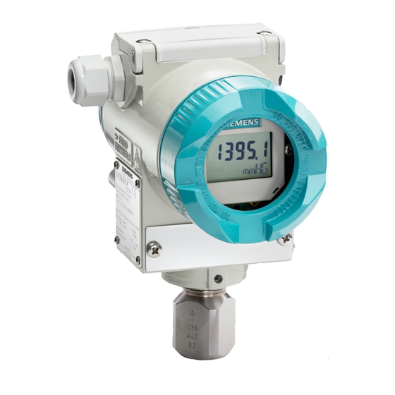
Side vent for measuring gas (supplement H02) M20 x 1.5 or ½ -14NPT or Mounting bracket (optional) Han 7D/Han 8 U plug Connection side This Figure is for Models 7MF4333, 7MF4433, and 7MF4533. FIGURE 9-3 Models 7MF4333, 7MF4433 and 7MF4533, Dimensions 9-12 November 2010... -
Page 171: Model 7Mf4333, Model Designation
UMSITRAPDS3-1 Model Designations and Specifications TABLE 9-5 Model 7MF4333, Model Designation Absolute pressure, differential pressure construction, two-wire, series DSIII, 7MF4333- Measuring cell filling Measuring cell cleaning Silicone oil Standard Inert liquid Grease-free Span 8.3 to 250 mbar a (0.12 to 3.63 psi a) 43 to 1300 mbar a (0.62 to 18.9 psi a) - Page 172 Model Designations and Specifications UMSITRPDS3-1 Additional Model 7MF4333 Selections and Data* Order Code Transmitter with mounting bracket of: - steel - stainless steel Process flange O-ring (instead of FPM (Viton®)) of: - PTFE (Teflon®) - FEP (with silicone core, approved for food) - FFPM (Kalrez®, compound 4079)
-
Page 173: Model 7Mf4333, Specifications
UMSITRAPDS3-1 Model Designations and Specifications TABLE 9-6 Model 7MF4333, Specifications Input Measured variable Absolute pressure (differential construction) Span (infinitely adjustable) Span Max. permissible test pressure 8.3 to 250 mbar a (0.12 to 3.6 psi a) see Note 32 bar a (464 psi a) 43 to 1300 mbar a (0.62 to 18.9 psi a) - Page 174 Model Designations and Specifications UMSITRPDS3-1 • Seal diaphragm Stainless steel, mat. No. 1.4404/316L or Hastelloy C4, mat. No. 2.4610, Monel, mat. No. 2.4360, tantalum or gold • Process flange and sealing screw Stainless steel, mat. No. 1.4408, Hastelloy C4, mat. No. 2.4610 or Monel, mat. No. 2.4360 •...
-
Page 175: Models 7Mf4433 And 7Mf4533, Differential Pressure And Flow
UMSITRAPDS3-1 Model Designations and Specifications 9.4 MODELS 7MF4433 AND 7MF4533, DIFFERENTIAL PRESSURE AND FLOW This section contains a dimension drawing of the transmitter (with the H03 option). A dimension drawing of the standard model is found in Figure 9-3. This section also contains a model designation table and performance specifications. -
Page 176: Model 7Mf4433, Model Designation
Model Designations and Specifications UMSITRPDS3-1 TABLE 9-7 Model 7MF4433, Model Designation Differential pressure and flow transmitters, two-wire, series DSIII, PN 470/2325, 7MF4433- Measuring cell filling Measuring cell cleaning Silicone oil Standard Inert liquid Grease-free Span PN 32 (MWP 464 psi) 1 to 20 mbar (0.4015 to 8.03 inH PN 160 (MWP 2320 psi) 1 to 60 mbar (0.4015 to 24.09 inH... - Page 177 UMSITRAPDS3-1 Model Designations and Specifications Additional Model 7MF4433 Selections and Data* Order code Transmitter with mounting bracket of: - Steel - Stainless steel ® Process flange O-ring (instead of FPM (Viton )) of: - PTFE (Teflon) - FEP (with silicone core, approved for food) - FFPM (Kalrez, compound 4079) - NBR (Buna N) Plug: Han 7D (metal, gray)
-
Page 178: Model 7Mf4533, Model Designation
Model Designations and Specifications UMSITRPDS3-1 TABLE 9-8 Model 7MF4533, Model Designation Differential pressure and flow transmitter, two-wire, series DSIII, Model 7MF4533- Measuring cell filling Measuring cell cleaning Silicon oil Standard Span 2.5 to 250 mbar (1.004 to 100.4 InH 6 to 600 mbar (2.409 to 240.9 InH 16 to 1600 mbar (6.424 to 642.4 InH... - Page 179 UMSITRAPDS3-1 Model Designations and Specifications Additional Model 7MF4533 Selections and Data* Order Code Transmitter with mounting bracket of: - Steel - Stainless steel O-rings for process flanges (instead of FPM (Viton)) of: - PTFE (Teflon) - FEP (with silicone core, approved for food) - FFPM (Kalrez, compound 4079) - NBR (Buna N) Plug: Han 7D (metal, gray)
-
Page 180: Models 7Mf4433 And 7Mf4533, Specifications
Model Designations and Specifications UMSITRPDS3-1 TABLE 9-9 Models 7MF4433 and 7MF4533, Specifications Input Measured variable Differential pressure and flow Span (infinitely adjustable) Span Max. permissible text pressure 1 to 20 mbar (0.4 to 8 inH 32 bar a (464 psi) 1 to 60 mbar (0.4 to 24 inH 160 bar a (2320 psi) 2.5 to 250 mbar (1 to 100 inH... - Page 181 UMSITRAPDS3-1 Model Designations and Specifications Influence of static pressure • on the zero point ≤ (0.15* r) % per 100 bar (1450 psi) - 20 mbar (0.29 psi)-measuring cell ≤ (0.15 % r)% per 32 bar (464 psi) • on the span ≤...
-
Page 182: Models 7Mf4633 And 7Mf4812, Level
Model Designations and Specifications UMSITRPDS3-1 9.5 MODELS 7MF4633 AND 7MF4812, LEVEL This section contains a dimension drawing of the transmitter, a model designation table and performance specifications. Process connection of low pressure side ¼ -18NPT Connection side Mounting thread M10, M12 or 7/16 –20 UNF Electronics side, digital display (greater length for Blanking plug cover with window) -
Page 183: Models 7Mf4633 And 7Mf4812, Model Designation
UMSITRAPDS3-1 Model Designations and Specifications TABLE 9-10 Models 7MF4633 and 7MF4812, Model Designation Flanged level transmitter, two-wire, series DSIII, 7MF4633- Measuring cell filling Measuring cell cleaning Silicone oil Standard Span 25 to 250 mbar (0.36 to 3.63 psi) 25 to 600 mbar (0.36 to 8.70 psi) 53 to 1600 mbar (0.8 to 23.2 psi) - Page 184 Model Designations and Specifications UMSITRPDS3-1 Additional Model 7MF4633 (7MF4812) Selections and Data* Order Code O-rings for process flanges on low pressure side (instead of FPM (Viton)) - PTFE (Teflon) - FEB (with silicone core, approved for food) - FFPM (Kalrez, compound 4079) - NBR (Buna N) Plug: Han 7D (metal, gray) Plug: Han 8U (instead of Han 7D)
- Page 185 UMSITRAPDS3-1 Model Designations and Specifications Flanged Level Transmitter Accessories Mounting flange, mounted directly on transmitter, two-wire, 7MF4812- Mounting Flange: Directly mounted on SITRANS P, DSIII series pressure transmitter (converter part) Flange Nominal diameter Nominal pressure Connection per DN 80 PN 40 EN 1092-1 DN 100 PN 16...
-
Page 186: Models 7Mf4633 And 7Mf4812, Specifications
Model Designations and Specifications UMSITRPDS3-1 TABLE 9-11 Models 7MF4633 and 7MF4812, Specifications Input Measured variable Level Span (infinitely adjustable) Span Max. permissible test pressure 25 to 250 mbar g (0.36 to 3.63 psi g) See Mounting Flange 25 to 600 mbar g (0.36 to 8.7 psi g) See Mounting Flange 53 to 1600 mbar g (0.77 to 23.2 psi g) See Mounting Flange... - Page 187 UMSITRAPDS3-1 Model Designations and Specifications • Measuring cell, silicon oil filling -40 to + 100°C (-40 to +212°F) - High-pressure side ρ ≥ 1 bar: -40 to +175°C (-40 to +347°F) ρ ≥ 1 bar: -40 to +80°C (-40 to +176°F) - Low pressure side -40 to +100°C (-40 to +212°F) -20 to +60°C (-4 to +140°F) in conjunction with dust explosion protection...
-
Page 188: Service Parts, All Models
Model Designations and Specifications UMSITRPDS3-1 9.6 SERVICE PARTS, ALL MODELS Tables 9-12 through 9-18 list the measuring cells and circuit boards available for servicing a transmitter described in this publication. TABLE 9-12 Measuring Cells for Pressure, Service Parts DS III and DS III PA series, 7MF4990- 0DC0 Measuring cell filling Measuring cell cleaning... -
Page 189: Measuring Cells For Absolute Pressure, Gauge Construction, Service Parts
UMSITRAPDS3-1 Model Designations and Specifications TABLE 9-13 Measuring Cells for Absolute Pressure, Gauge Construction, Service Parts DS III and DS III PA series, Gauge Construction, 7MF4992- 0DC0 Measuring cell filling Measuring cell cleaning Silicon oil Normal Inert liquid Grease-free Measuring span 8.3 to 250 mbar a (0.12 to 3.63 psi a) 43 to 1300 mbar a... -
Page 190: Measuring Cells For Pressure And Flow, Differential Const., Service Parts
Model Designations and Specifications UMSITRPDS3-1 Additional selections and data below Add “–Z” to the order number and specify Order Codes Order Code O-rings for process flanges (instead of FPM (Viton)): - PTFE (Teflon) - FEP (with silicone core, approved for food) - FFPM (Kalrez, compound 4079) - NBR (Buna N) Acceptance test certificate to EN 10204-3.1... -
Page 191: Measuring Cells For Differential Pressure And Flow, Service Parts
UMSITRAPDS3-1 Model Designations and Specifications Additional selections and data below Add “-Z” to the order number and specify Order Codes Order Code O-rings for process flanges (instead of FPM (Viton)): - PTFE (Teflon) - FEP (with silicone core, approved for food - FFPM (Kalrez, compound 4079) - NBR (Buna N) Acceptance test certificate to EN 10204-3.1... -
Page 192: Measuring Cells For Filling Level, Service Parts
Model Designations and Specifications UMSITRPDS3-1 TABLE 9-17 Measuring Cells for Filling Level, Service Parts DS III and DS III PA series, 7MF4996- 0DC0 Measuring cell filling Measuring cell cleaning Silicon oil Standard Rated measuring range 250 mbar (3.63 psi) 600 mbar (8.70 psi) 1600 mbar (23.2 psi) -
Page 193: Accessories
UMSITRAPDS3-1 Model Designations and Specifications 9.7 ACCESSORIES The following table lists some of the available accessories. Additional information about transmitter accessories can be found in Siemens publication Field Instruments for Process Automation, Catalog FI01. TABLE 9-19 Accessories MODEL 7MF... DESCRIPTION... -
Page 194: Hazardous Area Classification
Table 9-20 lists the hazardous area classifications available at the time this manual was printed. Contact your local Siemens representative or the factory for the latest classifications. CE Approval - A Declaration of Conformity can be found on a later page in this section. -
Page 195: Certificate And Approvals, All Models
(DRGL 97/23/EC) • Models 7MF4033, 7MF4233, For gasses of liquid group 1 and liquids of fluid group 1; complies with requirements 7MF4333, and 7MF4633 of Article 3, paragraph 3 (sound engineering practices) • Models 7MF4433 and 7MF4533 - PN 32/160 (MWP 464/ 2320 psi) For gasses of liquid group 1 and liquids of fluid group 1;... -
Page 196: Csa Hazardous Locations Precautions
Model Designations and Specifications UMSITRPDS3-1 Comply with your country’s laws and regulations that apply to electrical installation in an explosive environment. Be sure that the available power supply complies with the specifications on the transmitter rating plate and statements in the examination certificate in your country. Dust-proof protection caps in the cable inlets must be replaced by suitable screw-type gland or dummy plugs that must be appropriately certified for transmitters with explosion proof type of protection. - Page 199 UMSITRAPDS3-1 Model Designations and Specifications CERTIFICATE OF NACE COMPLIANCE Siemens Energy & Automation, Inc. 1201 Sumneytown Pike Spring House, PA 19477 certifies under its sole responsibility that a SITRANS DSIII Pressure Transmitter with one of the following factory configured options...
- Page 200 Model Designations and Specifications UMSITRPDS3-1 9-42 November 2010...
-
Page 201: Glossary
UMSITRPDS-1 Glossary 10.0 GLOSSARY Defined below are terms relevant to the SITRANS P DSIII transmitter, this User’s Manual, pressure measurement technology, and HART networks. Absolute (abs) Pressure – A pressure measured against absolute zero or a total vacuum as a reference. The units of measurement are called absolute pressure units. - Page 202 Glossary UMSITRPDS3-1 Field Instrument – A network element that uses current variation for digital signaling or digital plus analog signaling. Gauge Pressure – A pressure measured against atmospheric or barometric pressure as a reference. The units of measurement are called gauge pressure units. For example: psig = pounds per square inch gauge. HART –...
- Page 203 UMSITRPDS-1 Glossary Network Element – Any field instrument or primary or secondary master. Network Resistance – The sum of the current sense resistance, barrier resistance, if any, and any other resistance on the network. NPT – National Pipe Thread Point-To-Point Network – A network having a single field instrument and primary master. Analog signaling or analog plus digital signaling is possible.
- Page 204 Glossary UMSITRPDS3-1 10-4 November 2010...
-
Page 205: Appendix A - Online Configuration Map
UMSITRPDS3-1 Appendix A - Online Configuration Map 11.0 APPENDIX A - ONLINE CONFIGURATION MAP This Appendix contains a detailed configuration map showing the available online configuration options when using the Model 275 HART Communicator – see the Note below. Note: The Configuration Map for the Model 375 Field Communicator is shown at the back of this manual. -
Page 206: Online Configuration Map, Part 1 Of 2
Appendix A - Online Configuration Map UMSITRPDS3-1 1 Pressure + 2 Type + 3 Device setup 1 Process variables 1 Pressure + 2 % range + 3 Analog output + 4 Sensor temperature + 2 Diagnostics/service 1 Diagnosis 1 Min/max pointer 1 Pressure pointer 1 Pressure maximum 2 Pressure minimum... -
Page 207: Online Configuration Map, Part 2 Of 2
UMSITRPDS3-1 Appendix A - Online Configuration Map 4 Detailed setup 1 Sensors 1 Pressure sensor 1 Pressure + See Note 4 2 (Engineering) Units 2 Temperature sensor 1 Sensor temperature + 3 Device setup, 2 El temperature + continued in 2 Signal condition 1 Process variables 1 Pressure +... - Page 208 Appendix A - Online Configuration Map UMSITRPDS3-1 11-4 November 2010...
-
Page 209: Appendix B - Hazardous Area Installation
UMSITRPDS3-1 Appendix B - Hazardous Area Installation 12.0 APPENDIX B - HAZARDOUS AREA INSTALLATION This Appendix presents wiring and barrier selection information for installation of the transmitter in a hazardous location. The installer should carefully select barriers based on the required protection, loop wiring, manufacturer’s barrier performance data, and the data in the control drawings in this section. -
Page 210: Control Drawing
Appendix B - Hazardous Area Installation UMSITRPDS3-1 FIGURE 12-1 Control Drawing 12-2 November 2010... -
Page 211: Control Drawing
UMSITRPDS3-1 Appendix B - Hazardous Area Installation FIGURE 12-2 Control Drawing 12-3 November 2010... -
Page 212: Control Drawing
Appendix B - Hazardous Area Installation UMSITRPDS3-1 FIGURE 12-3 Control Drawing 12-4 November 2010... -
Page 213: Appendix C - Elevation And Suppression Corrections
UMSITRPDS3-1 Appendix C - Elevation and Suppression Corrections 13.0 APPENDIX C - ELEVATION AND SUPPRESSION CORRECTIONS When installing a transmitter to measure liquid level, configuration of the Sensor Input Block often must include an adjustment for one of two conditions introduced by the mounting arrangement: •... -
Page 214: Elevation Calculation Example
Appendix C - Elevation and Suppression Correction UMSITRPDS3-1 Note that the URL (Upper Range Limit), LRL (Lower Range Limit), and Min Span are transmitter dependent. 13.2 ELEVATION CALCULATION EXAMPLE Figure C-3 shows a sample transmitter installation. 1. Calculate the differential pressure as follows. Max. -
Page 215: Recommended Method
UMSITRPDS3-1 Appendix C - Elevation and Suppression Corrections 13.4 RECOMMENDED METHOD An alternative to making the above calculations and entering derived values is to shift the span directly using the HART Communicator while adjusting the process levels. 1. Range the transmitter using the HART Communicator as for a zero-based span (e.g., 0-100 inH 2. - Page 216 Appendix C - Elevation and Suppression Correction UMSITRPDS3-1 13-4 November 2010...
- Page 217 Online Configuration Map for Siemens SITRANS P DSIII Pressure Transmitters (with Model 275 HART COMMUNICATOR) 1 Pressure + 2 Type + 3 Device setup 1 Process variables 1 Pressure + 2 % range + 3 Analog output + 4 Sensor temperature +...
- Page 218 Online Configuration Map for Siemens SITRANS P DSIII, Continued 4 Detailed setup 1 Sensors 1 Pressure sensor 1 Pressure + See Note 4 2 (Engineering) Units 2 Temperature sensor 1 Sensor temperature + 3 Device setup, 2 El temperature +...
- Page 219 Online Configuration Map for Siemens SITRANS P DSIII Pressure Transmitter with Model 375 Field Communicator Notes: 1 Model 375 Field Communicator Firmware Rev. F1.6 2 Online 1 Pressure (PV) + 2 PV status 2 + = active data (measurement) display 3 Module type M = method (i.e.
- Page 220 Online Configuration Map for Siemens SITRANS P DSIII Pressure Transmitter with Model 375 Field Communicator 5 Config Inp/Outp, 2 Input, Continued 3 Meas Switch/Mapper 1 measurement Continued 2 PV is 3 SV is 4 TV is 5 QV is 6 (measurement) config...
- Page 221 Online Configuration Map for Siemens SITRANS P DSIII Pressure Transmitter with Model 375 Field Communicator 5 Config inp/outp, 3 Output 1 Analog output 1 Analog output + Continued 2 Percent range + 3 Pres xfer function Linear Sq Rt, lin to Strtpt...
- Page 222 Online Configuration Map for Siemens SITRANS P DSIII Pressure Transmitter with Model 375 Field Communicator 6 Diagnosis/Service, 3 Diagnostic settings 1 W/A time unit W/A = warning/alarm Continued 2 Calib interval 1 Calib status 2 W/A acknowledge --> M 3 Calib timer 1 Calib time 2 Reset timer -->...
Need help?
Do you have a question about the 7MF4333 and is the answer not in the manual?
Questions and answers