Sign In
Upload
Download
Table of Contents
Contents
Add to my manuals
Delete from my manuals
Share
URL of this page:
HTML Link:
Bookmark this page
Add
Manual will be automatically added to "My Manuals"
Print this page
×
Bookmark added
×
Added to my manuals
Manuals
Brands
Siemens Manuals
Transmitter
7MF4912 series
User manual
Siemens 7MF4912 series User Manual
Sitrans p ds iii series pressure, differential pressure, flanged level, and absolute pressure
Hide thumbs
1
2
3
Table Of Contents
4
5
6
7
8
9
10
11
12
13
14
15
16
17
18
19
20
21
22
23
24
25
26
27
28
29
30
31
32
33
34
35
36
37
38
39
40
41
42
43
44
45
46
47
48
49
50
51
52
53
54
55
56
57
58
59
60
61
62
63
64
65
66
67
68
69
70
71
72
73
74
75
76
77
78
79
80
81
82
83
84
85
86
87
88
89
90
91
92
93
94
95
96
97
98
99
100
101
102
103
104
105
106
107
108
109
110
111
112
113
114
115
116
117
118
119
120
121
122
123
124
125
126
127
128
129
130
131
132
133
134
135
136
137
138
139
140
141
142
143
144
145
146
147
148
149
150
151
152
153
154
155
156
157
158
159
160
161
162
163
164
165
166
167
168
169
170
171
172
173
174
175
176
177
178
179
180
181
182
183
184
185
186
187
188
189
190
191
192
193
194
195
196
197
198
199
200
201
202
203
204
205
206
207
208
209
210
211
page
of
211
Go
/
211
Contents
Table of Contents
Troubleshooting
Bookmarks
Table of Contents
Table of Contents
Contents
1 Introduction
Product Description
Gauge Construction, Pressure and Absolute Pressure Models
Differential Construction; Differential, Flow, and Absolute Models
Differential Pressure and Flow Models with H03 Option
Flanged Liquid Level Models
Traditional Application
Display
Configuration
Rating, Approval, and Tag Plates
2 Model 275 Universal Hart Communicator
Introduction
Communicator Connections
Model 275 Universal HART Communicator
HART Communicator Connections to a Transmitter Loop
Controls Overview
Liquid Crystal Display
Software-Defined Function Keys
Function Keys with Their Labels and Actions Performed
Action Keys
Alphanumeric and Shift Keys
Data Entry
Rapid Selection of Menu Options
Getting to Know the Communicator
Display Icons
Menu Structure
Reviewing Installed Devices
Communicator Firmware Device Descriptions, Rev. F2.2
Main Menu
Offline Menu
New Configuration
Saved Configuration
Online Menu
SITRANS P Online Menu Map
Generic Online Menu Map
Frequency Device Menu
Utility Menu
Configure Communicator
Listen for PC
Selftest
Simulation
Storage Location
System Information
Using the Quick Access Key
Adding Quick Access Key Options
Deleting Quick Access Key Options
3 Pre-Installation Test
Procedure
Test Equipment
Establishing Communication
Testing the Transmitter
Reviewing Configuration Data
Checking Transmitter Output
4 Installation
Equipment Delivery and Handling
Receipt of Shipment
Storage
Environmental Considerations
Pre-Installation Considerations and Calculations
Mechanical
Electrical
Impulse Piping for Absolute and Differential Models
Differential Flow Measurement Piping for Gas and Liquid
Differential Liquid Measurement Piping
Absolute or Gauge Pressure Measurement Piping
Steam Service, below the Line Mounting
Open and Closed Tank Level Measurement, Flange Mounted Transmitters
Transmitter Operating Mode and Network Type
Analog Mode
Point-To-Point Network (Analog Mode)
Procidia to Transmitter Connections (Analog Mode)
Model 353/354 to Transmitter Connections (Analog Mode)
Digital Mode
Power Supply Requirements
Multi-Drop Network (Digital Mode)
Point-To-Point Network
Multi-Drop Network
Determining Network (Loop) Length
Cable Capacitance
Maximum Cable Length Calculation
Network Junctions
Safety Barriers
Connection of Miscellaneous Hardware
Shielding and Grounding
Mechanical Installation
Pipe Mounting, Differential and Gauge Construction
Pipe Mounting, Gauge Construction
Direct Mounting to Process, Model 7MF4433 or 7MF4533
Flange Mounting, Model 7MF4633/7MF4912
Flange and Extension Dimensions
MECHANICAL INSTALLATION, All Models
Enclosure Rotation
Display Orientation
Conduit
Electrical Conduit and Cable Installation
Access to Transmitter Terminal Compartment
Cables
Electrical Installation
Network Conductor Terminations
Hazardous Area Installation
5 Post-Installation Test
Test Equipment
Installation Review
Equipment Connection
Verification
Communication Test
Transmitter Selftest
Loop Test
Transmitter Zero and Shutoff Valve Manipulation
Absolute Pressure
Measuring Gases
Measuring Vapor and Liquid
Differential Pressure and Flow
Measuring Gases
Measuring Liquids
Measuring Liquids
Measuring Vapor
6 On-Line Configuration and Operation
Local Operation and Display
Digital Display
Numeric Display
Unit/Bargraph Display
Error Message
Output Signal Range
Mode Display
Local Operation with the Magnetic Pushbuttons
Parameters Accessible Using the Magnetic Pushbuttons
Cancel Pushbutton Disable and Write Protection
Set/Adjust Zero and Full Scale
Theoretical Relationships
Practical Applications
Blind Setting of Zero and Full Scale
Electric Damping
Theoretical Relationships
Practical Applications
Zero Adjustment (Position Correction)
Zero-Point Alignment at Absolute Pressure
Failure Current
Fixed Current Output
Flow Measurement (Differential Pressure Only)
Pushbutton and Function Disable
Switch Point of the Square Root Characteristic
Select Measured Value to be Displayed
Select the Displayed Input Pressure Engineering Unit
Displayable Engineering Units
Local Operation Without a Display or with Activated Keylock
Set Zero and Full Scale
Remote Configuration and Operation by Hart
Process Data
Blind Setting of Zero and Full Scale
Setting Zero and Full Scale
Zero Adjustment for Position Correction
Electric Damping
Fast Measured Value Acquisition (Fast Response Mode)
Fault Current
Fixed Current Output
Disabling the Transmitter Magnetic Pushbuttons and Write Protection
Display/Bargraph
Measured Value Display
Select Pressure Engineering Units
Sensor Trim
Trimming the Lower Sensor Adjustment Point
Trimming the Upper Sensor Adjustment Point
D/A Trim
Transmitter Current Adjustment
Factory Calibration (Manufacturer Trims)
Device Information
Diagnostic Functions
Flow Measurement (Differential Pressure)
Calibration Timer and Service Timer
Operating Hours Counter
Min/Max Pointer
Monitoring the Saturation Current
Simulation
Self Test and Master Reset
7 Calibration and Maintenance
Calibration
Preventive Maintenance
Transmitter Exterior Inspection
Transmitter Exterior Cleaning
Transmitter Enclosure Interior Inspection
Transmitter Calibration
Impulse Piping
Troubleshooting
Analog Output
Digital Output (Communication)
Assembly Removal and Replacement
Display Assembly
Replacing the Electronics Module
Measuring Cell Assembly Removal and Replacement
Terminal Board Assembly Removal and Replacement
Non-Field-Replaceable Items
Transmitter Replacement
Maintenance Records
Recommended Spare and Replacement Parts
COMPATIBILITY, Revision Numbers
8 Circuit Description
Overall Operation
Pressure
Differential Pressure and Flow
Flanged Level
Absolute Pressure (Differential Construction)
Absolute Pressure (Gauge Construction)
Communication Format
9 Model Designations and Specifications
Model Designations
Model 7MF4033, Model Designation
Model 7MF4233, Model Designation
Model 7MF4333, Model Designation
Model 7MF4433, Model Designation
Model 7MF4533, Model Designation
Models 7MF4633 and 7MF4912, Model Designation
Accessories
Specifications
Measuring Spans and Overload Limits
Network Topology
Two-Wire Cable
HAZARDOUS AREA Classifications
CSA Hazardous Locations Precautions
10 Glossary
11 Appendix A - Online Configuration Map
Online Configuration Map, Part 1 of 2
Online Configuration Map, Part 2 of 2
12 Appendix B - Hazardous Area Installation
Control Drawing
Control Drawing
13 Appendix C - Elevation and Suppression Corrections
How Adjustment Is Made
Elevation Calculation Example
Recommended Method
Advertisement
Quick Links
1
Product Description
2
Configuration
3
Model 7Mf4033, Model Designation
Download this manual
See also:
Installation Manual
Siemens
Energy & Automation
SITRANS P, Series DSIII Transmitter
Pressure, Differential Pressure,
Flanged Level, and Absolute Pressure
USER'S MANUAL
for
Model 7MF4*33-...
UMSITRPDS3-1
Rev. 6
November 2005
Supersedes Rev. 5
Table of
Contents
Previous
Page
Next
Page
1
2
3
4
5
Advertisement
Table of Contents
Need help?
Do you have a question about the 7MF4912 series and is the answer not in the manual?
Ask a question
Questions and answers
Related Manuals for Siemens 7MF4912 series
Transmitter Siemens SITRANS P200 Operating Instructions
Pressure transmitter (4 pages)
Transmitter Siemens 7MF1570 User Manual
Pressure transmitter for level measurement (14 pages)
Transmitter Siemens 7MF4033 series User Manual
Sitrans p ds iii series pressure, differential pressure, flanged level, and absolute pressure (211 pages)
Transmitter Siemens 7MF4033 Installation Manual
Sitrans p, series dsiii transmitters for pressure, differential pressure, flanged level, and absolute pressure (16 pages)
Transmitter Siemens 7MF4333 User Manual
Sitrans p, series dsiii transmitters for pressure, differential pressure, flanged level, and absolute pressure (222 pages)
Transmitter Siemens 7MF4133 Installation Manual
Sitrans p, series dsiii transmitters for pressure, differential pressure, flanged level, and absolute pressure (16 pages)
Transmitter Siemens SITRANS P DS III Manual
Sitrans tank level transmitter (282 pages)
Transmitter Siemens SITRANS P220 Operating Instructions Manual
Pressure transmitter (8 pages)
Transmitter Siemens SITRANS P300 Operating Instructions Manual
Pressure transmitter (187 pages)
Transmitter Siemens 7MF8.23 Series Compact Operating Instructions
Pressure transmitter (185 pages)
Transmitter Siemens 7MF03 Series Compact Operating Instructions
Pressure transmitter with 4 to 20 ma/hart (106 pages)
Transmitter Siemens SITRANS P MK II Series Instruction Manual
Transmitter for pressure (67 pages)
Transmitter Siemens SITRANS TH100Slim Compact Operating Instructions
Temperature transmitter (98 pages)
Transmitter Siemens SITRANS P320 Compact Operating Instructions
Pressure transmitter (98 pages)
Transmitter Siemens SITRANS P320 Service Manual
Pressure transmitter (48 pages)
Transmitter Siemens SITRANS TH100 Operating Instructions Manual
Temperature transmitter with 4to 20 ma/hart (236 pages)
Summarization of Contents
1.0 Introduction
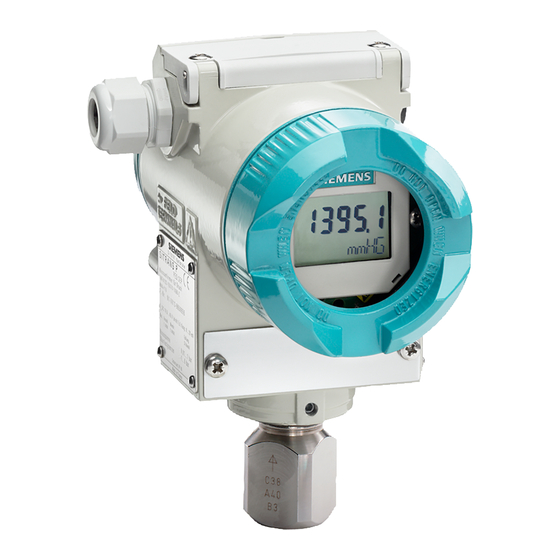
1.2 Product Description
Overview of SITRANS P DSIII transmitters, their function, and core components.
1.3 Rating, Approval, and Tag Plates
Information on transmitter rating, approval, and tag plates for identification.
1.4 Configuration
Details on transmitter configuration methods and storage.
1.5 Product Support
Information on where to get support for the product.
2.0 Model 275 Universal HART Communicator
2.1 Introduction
Introduction to the HART communicator's role and capabilities.
2.2 Communicator Connections
Procedures for connecting the HART communicator to a transmitter loop.
2.3 Controls Overview
Description of the HART communicator's functional areas: display, keys, and buttons.
2.4 Getting to Know the Communicator
Explains communicator operation modes, display icons, and menu structures.
2.5 Main Menu
Navigation through the HART communicator's main menu options.
2.6 Using the Quick Access Key
Instructions on utilizing the Quick Access Key for frequent tasks.
3.0 Pre-Installation Test
3.1 Procedure
Steps for performing a complete transmitter functional test before installation.
3.2 Establishing Communication
Procedure for establishing communication between HART communicator and transmitter.
3.3 Testing the Transmitter
Performing an extended self-test on the transmitter.
3.4 Reviewing Configuration Data
Ensuring stored configuration data is correct before placing transmitter in service.
3.5 Checking Transmitter Output
Verifying transmitter output accuracy by applying pressure and checking current.
4.0 Installation
4.1 Equipment Delivery and Handling
Guidelines for receiving, inspecting, and storing transmitter equipment.
4.2 Environmental Considerations
Selecting transmitter locations to minimize environmental effects.
4.3 Pre-Installation Considerations and Calculations
Essential considerations and calculations for successful mechanical and electrical installations.
4.4 Mechanical Installation
Describes mechanical installation of transmitters and electrical conduit.
4.5 Mechanical Installation, All Models
Rotating enclosure, orienting display, and installing electrical conduit.
4.6 Electrical Installation
Details loop wiring for Point-to-Point and Multi-Drop networks, including hazardous locations.
4.7 Hazardous Area Installation
Specific wiring and barrier selection for hazardous location installation.
5.0 Post-Installation Test
5.1 Test Equipment
Lists required equipment for post-installation testing and calibration.
5.2 Installation Review
Verifying correct transmitter model and installation against documentation.
5.3 Equipment Connection
Shows how to connect test equipment for system checkout.
5.4 Verification
Tests for communication, error checks, analog output, and configuration.
5.5 Transmitter Zero and Shutoff Valve Manipulation
Procedures for setting transmitter zero and adjusting shutoff valves for live process pressures.
6.0 On-Line Configuration and Operation
6.1 Local Operation and Display
Using built-in magnetic pushbuttons and optional digital display for local control.
6.2 Local Operation with the Magnetic Pushbuttons
Configuring the transmitter locally using magnetic pushbuttons.
6.3 Local Operation Without a Display or With Activated Keylock
Limited local operation when display is absent or pushbuttons are disabled.
6.4 Remote Configuration and Operation by HART
Configuring and monitoring the transmitter using the HART Communicator.
7.0 Calibration and Maintenance
7.1 Calibration
Adjusting zero, setting zero online, and trimming the D/A converter for accuracy.
7.2 Preventive Maintenance
Procedures for periodic inspection and cleaning to maintain transmitter reliability.
7.3 Troubleshooting
Guidance for identifying and correcting transmitter malfunctions.
7.4 Assembly Removal and Replacement
Procedures for removing and replacing transmitter assemblies like display and electronics.
7.5 Non-Field-Replaceable Items
Lists components not replaceable in the field, requiring factory service.
7.6 Transmitter Replacement
Step-by-step procedure for replacing a transmitter, including removal and installation.
7.7 Maintenance Records
Importance of maintaining accurate records for tracking operations and supplies.
7.8 Recommended Spare and Replacement Parts
Information for ordering spare parts to minimize downtime.
7.9 Compatibility, Revision Numbers
How to view and identify software and hardware revision numbers.
8.0 Circuit Description
8.1 Overall Operation
Explains the basic operation of the transmitter's sensor and electronics module.
8.2 Pressure
Describes the pressure measurement cell and how pressure is applied.
8.3 Differential Pressure and Flow
Details the measuring cell for differential pressure and flow applications.
8.4 Flanged Level
Explains the measuring cell design for flanged level transmitters.
8.5 Absolute Pressure (Differential Construction)
Describes the measuring cell for absolute pressure with differential construction.
8.6 Absolute Pressure (Gauge Construction)
Describes the measuring cell for absolute pressure with gauge construction.
8.7 Communication Format
Details the HART communication protocol and signal format.
9.0 Model Designations and Specifications
9.1 Model Designations
Explains how to interpret model numbers from rating and approval plates.
9.2 Accessories
Lists available accessories for SITRANS P transmitters.
9.3 Specifications
Provides detailed technical specifications for transmitter models.
9.4 Measuring Spans and Overload Limits
Tables detailing measuring spans and maximum working pressure limits.
9.5 Network Topology
Information on Point-to-Point and Multi-Drop network configurations.
9.6 Hazardous Area Classifications
Lists hazardous area classifications and safety precautions for installation.
10.0 Glossary
11.0 Appendix A - Online Configuration Map
12.0 Appendix B - Hazardous Area Installation
13.0 Appendix C - Elevation and Suppression Corrections
13.1 How Adjustment Is Made
Explains how to adjust for elevation and suppression by setting parameters.
13.2 Elevation Calculation Example
A calculation example for elevation span adjustment.
13.3 Suppression Calculation Example
A calculation example for suppression span adjustment.
13.4 Recommended Method
An alternative method for shifting span using HART communicator.
Warranty
Table of Contents
Save PDF
Print
Rename the bookmark
Delete bookmark?
Delete from my manuals?
Login
Sign In
OR
Sign in with Facebook
Sign in with Google
Upload manual
Upload from disk
Upload from URL
Need help?
Do you have a question about the 7MF4912 series and is the answer not in the manual?
Questions and answers