Keba KeContact P20 Installation Manual
Hide thumbs
Also See for KeContact P20:
- User manual (200 pages) ,
- Manual (128 pages) ,
- Installation manual (60 pages)
Table of Contents
Advertisement
Quick Links
Advertisement
Table of Contents

Related Manuals for Keba KeContact P20


Summary of Contents for Keba KeContact P20
- Page 1 KeContact P20 Installation manual (for the specialist)
- Page 2 All brand and product names are trademarks of their respective companies. Technical information in this document is subject to change without notice. Document: Revision 1.70 / Release date: 20.08.2014 / Article no.: 90064 KEBA AG, Postfach 111, Gewerbepark Urfahr, A-4041 Linz; www.kecontact.com...
- Page 3 (such as iron filings, wire wool contaminated with oil etc.). The latest KeContact P20 firmware can be downloaded from the Internet at www.kecontact.com (download area). A new firmware can eg. consider modified standards or improve the compatibility with new electric vehicles.
-
Page 4: Table Of Contents
Contents Contents Important information ........................5 Safety instructions ......................... 5 Intended use .......................... 7 About this manual........................7 Product description........................ 8 Overview ............................9 Optional equipment (except e-series) ................... 9 2.1.1 Additional optional equipment ................10 Installation guidelines ......................... 11 General criteria for the site selection................... -
Page 5: Important Information
1.1 Safety instructions WARNING! Not observing the safety instructions can result in risk of death, injuries and dam- age to the device! KEBA AG assumes no liability for claims resulting from this! Electrical hazard! The installation, commissioning and maintenance of the charging station may... - Page 6 Important information WARNING! Pull the charging cable only at the plug and not at the cable out of the con- nector. Ensure that the charging cable is not mechanically damaged (bent, pinched or run over) and the connection area does not come into contact with heat sources, dirt or water.
-
Page 7: Intended Use
Important information 1.2 Intended use KeContact P20 is a "charging station" for the indoor and outdoor area at which electrically operated vehicles can be charged (e.g. electric automobiles). The charging station is designed for installation on a wall or in a floor-mounted column. -
Page 8: Product Description
Important information 1.4 Product description Example KC-P20-ES240030-000-xxxx Type plate Product family Product type Type / Version see top of the device Design versions Basic versions Cable / Socket Electronics Electrics Options Optional Customer code Buttons Authentication 2-digit Left Right 8 / 48... -
Page 9: Overview
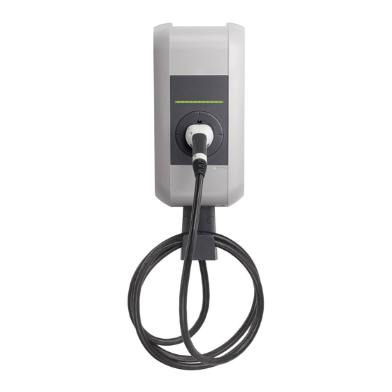
Overview 2 Overview Typical version with charging cable [A]… Status LED [B1]… Parking bay for charging plug [B2]… Standard socket (variants possible) [C]… Housing cover [D]… Hanger for charging cable Note Depending on the design of the charging sta- tion, the parking bay may deviate from the form shown. -
Page 10: Additional Optional Equipment
Overview 2.1.1 Additional optional equipment Network capability Switch contact (for control of external additional equipment) Enable input for e.g. ripple control receivers, time switches,… This permits a scheduled (time-controlled) charging of the vehicle to be realized. PLC (Power Line Communication) according to GreenPhy standard ... -
Page 11: Installation Guidelines
Installation guidelines 3 Installation guidelines 3.1 General criteria for the site selection The charging station was constructed for the indoor and outdoor area. Accordingly, it is necessary to ensure the installation conditions and the protection of the device at the installation site. ... -
Page 12: Specifications For The Electrical Connection
Installation guidelines 3.2 Specifications for the electrical connection 3.2.1 General The charging station is set to 10 amps in the delivery state. Set the maximum EVSE current capac- ity by setting the DIP-switches in coordination with your installed line circuit breaker (see chapter “DIP-switch settings”). -
Page 13: Differing Requirements For The Fulfillment Of „Z.e.-Ready®" (Renault)
No 13A charging cables may be used. For 3-phase connection of the KeContact P20, at least a fault-current circuit breaker RCD type A with DC fault current detection (>6mA) or a fault-current circuit breaker RCD type B must be used. -
Page 14: Space Requirements
Installation guidelines 3.3 Space requirements Space requirements For device versions with optional cable hanger, additional and sufficient free area (y) for the charging cable to be used is to be accounted for. If several charging stations are installed adja- cent to each other, a distance of at least 200 mm between charging stations must be com- plied with. -
Page 15: Installation
Installation 4 Installation Scope of supply e-series others Charging station 1 piece 1 piece Cable hanger (for versions with charging cable) 1 piece 1 piece Installation manual (for the specialist) 1 piece 1 piece User manual (for the end customer) 1 piece 1 piece Drilling template... - Page 16 Installation Installation requirements Before beginning the installation, the installation guidelines must be observed. Contact person on-site (for access to the mains disconnector in the electrical distribution panel board). The electrical connection (mains supply line) must be prepared. ...
-
Page 17: Preparing The Housing
Installation 4.1 Preparing the housing 4.1.1 Removing the housing cover Cover screws ► Unscrew the two cover screws [S] on the bottom side of the housing cover. Cover screws Removing the housing cover ► (1) Pull the housing cover out slightly. ►... -
Page 18: Removing/Mounting The Connector Panel Cover
Installation 4.1.2 Removing/mounting the connector panel cover Removing the connector panel cover ► Unscrew the four screws with which the connector panel cover is mounted and remove the connector panel cover. Notice Remove the dry bag from the connector panel and dispose it of properly. -
Page 19: Preparing The Cable Insertion
Installation 4.2 Preparing the cable insertion There are two possibilities available for the cable insertion: Cable insertion from above (surface cable routing) Cable insertion from behind (flush-type cable routing) Preparations ► Remove the connector panel cover (see Chapter "Removing/mounting the cable panel cover"). -
Page 20: Cable Insertion From Above - Surface Cable Routing
Installation 4.2.1 Cable insertion from above - surface cable routing Cable insertion openings - top view [A]…Cable gland M32 (mains supply line) [B]…Cable gland M16 (for control line/Ethernet) [C]…Cable gland M16 (for control line/Ethernet) 4.2.2 Cable insertion from behind - flush-type cable routing Cable insertion openings - front view [A]…... -
Page 21: Mounting The Charging Station
Depending on the device model or in case of special materials, the mounting materials must be made available on site. A proper mounting is absolutely necessary and lies outside of the scope of responsibility of KEBA AG. Please also observe the following manufacturer instructions: Instructions for placing anchors and bolts. Source: Fischer... - Page 22 Installation Marking the holes ► Mark the four holes [1] to [4] using the supplied drilling template and a spirit level. ► Drill the four mounting holes. Information about the drilling template: The drilling template shows the outer contour of the charging station.
- Page 23 Installation Mounting the charging station ► Turn the hanger bolts into the anchors until the thread still protrudes approx. 2 cm ('x'). ► Use the shims [A] to compensate for any unevenness and to ensure a water drainage behind the device. ►...
-
Page 24: Electrical Connection
Installation 4.4 Electrical connection 4.4.1 Connection overview with opened connector panel cover Connection overview [1]… - Phase conductor 1 [T1]… Service button Mains supply terminal [2]… - Phase conductor 2 [LED]…Status LED (internal) Mains supply terminal [3]… - Phase conductor 3 [X1]…... -
Page 25: Connecting The Mains Supply Line
Installation 4.4.2 Connecting the mains supply line Running the mains supply line (surface cable routing) ► Run the mains supply line from ABOVE as shown in the figure. [M]… cable sheathing Running the mains supply line Running the mains supply line (flush-type cable routing) ►... - Page 26 Installation Connecting the mains supply line ► Shorten the connection wires to the appropriate length; these should be kept as short as possible. The PE conductor must be longer than the remaining conductors! ► Strip approx.12 mm from the connection wires.
- Page 27 Installation Opening the supply terminal ► Push the screwdriver with moderate force straight into the terminal until the wire connector is completely open. During pushing into the supply terminal, the angle of the screwdriver is changing. ATTENTION Risk of breaking the terminal! Do not pry the screwdriver up, down or to the side! Opening the supply terminal...
-
Page 28: Enable Input [X1] (Except E-Series)
Installation 4.4.3 Enable input [X1] (except e-series) The enable input is equipped for the use with a potential-free contact. Using the enable input, it is possible to control the charging station using external components (e.g. external key switches, ripple control receiver of the energy supplier, house control, time switches, combination lock, pho- tovoltaic system etc.). -
Page 29: Switch Contact Output [X2] (Except E-Series)
Installation 4.4.4 Switch contact output [X2] (except e-series) The switch contact output (signal contact) is a potential-free relay contact and signals a fault for the internal contactor. If the output is used, the corresponding DIP switch setting must be selected. Circuit diagram: Electrical requirements: - Safety extra-low voltage Vcc <... -
Page 30: Terminals [X1/X2] (Except E-Series)
Installation Example (supplement to the circuit diagram): The switch contact can be used to switch off the KeContact P20 (disconnect the current) by means of an overriding disconnect solution. -Q1… Main circuit breaker -Q2… Line circuit breaker + RCD circuit breaker -Q3…... -
Page 31: Ethernet1 Connection [Eth] (Optional)
Installation 4.4.6 Ethernet1 connection [ETH] (optional) WARNING! Danger from compensation currents on shielding! Compensation currents flowing through shielding in extended systems can lead to damage to the interfaces and hazards when working on the data lines. Any measures (such as connecting to a shared distribution board, expanding a TN-S network, etc.) should be discussed with the person responsible for build- ing services. - Page 32 Installation LSA+® insertion tool Original KRONE insertion tool with solder-free and stripping-free connection of the wires and simultaneous trimming of the residual lengths. LSA+® insertion tool Preparing the connection cable ► Strip the connection cable approximately 6 cm. ► Fold back approx. 1 cm of shielded braiding completely and wrap it with conductive adhesive textile tape.
-
Page 33: Dip-Switch Settings
Installation 4.5 DIP-switch settings Changes in the DIP-switch settings will take effect once the charging station has been restarted! To do this press the [Service button] for 1 second or switch the power supply voltage off/on. DIP-switches The DIP-switches are used for the addressing and configuring the charging station and are located under the connector panel cover. - Page 34 Installation PHASES / ONLY FOR LOAD MANAGEMENT MODE DSW1.3 to DSW1.5 Function DIP-switch Figure only 1 phase Supply (phases) D1.3 OFF= all Phases Phase assignment (*) D1.4 D1.5 Figure Phase L1 at terminal 1 connected Phase L2 at terminal 1 connected Phase L3 at terminal 1 connected...
- Page 35 Installation Only one maximum value can be set with the following DIP switches which is smaller or equal to the operating current according to the type plate: SETTING THE AMPERAGE (DSW1) (*1) Current D1.6 D1.7 D1.8 Figure (*1) Preadjusted maximum current value for the EV charger (control pilot duty cycle). STANDARD MODE + DHCP (NO ADDRESSING) DSW2.1 to DSW2.4=OFF / DSW2.6=OFF The charging procedure in STANDARD mode is...
- Page 36 Installation STANDARD MODE + ADDRESSING DSW2.6=ON The charging procedure in STANDARD mode is carried out automatically by the charging station without higher-ranking control system. The charging station has the static IP address: Example: address 17 [192.168.25.xx] Set the desired IP address with the DIP- switches DSW2.1 to DSW2.4 (see “Address- ing”).
-
Page 37: Commissioning
Installation COMMISSIONING MODE (DSW2.8) Function DIP-switch Figure Commissioning mode D2.8 ON=yes activate Set D2.1 to D2.7 to OFF! 4.6 Commissioning General commissioning process 1. Remove all residual installation and connection materials from the connection area. 2. Before commissioning, check all screw and terminal connections for firm seating! 3. -
Page 38: Commissioning Mode/Self Test
Installation 4.6.1 Commissioning mode/self test General The charging station can be placed into a commissioning mode for supporting the initial system test. During this, a self test of the device is performed (interlocking, contactor activation, current measurement, etc.) and the result is displayed. After successful test without connected vehicle, the contactor is switched for limited time in order to facilitate the initial tests. -
Page 39: Safety Checks
Installation 4.6.2 Safety checks Before the initial use, check the effectiveness of the safety measure(s) of the system according to the nationally applicable regulations (e.g.:ÖVE/ÖNORM E8001-6-61, DIN VDE 0100-600:2008-06 "Checks,...")! Electrical systems or devices must be checked by the installer of the system or device before their initial operation. -
Page 40: Mounting The Housing Cover
Installation 4.6.3 Mounting the housing cover Fitting the housing cover ► Fit the housing cover at the top and push the cover downwards slightly. Make sure that the housing cover is seated correctly at the top in the housing guides. Fitting the housing cover Mounting the housing cover ►... -
Page 41: Further Technical Instructions
Further technical instructions 5 Further technical instructions 5.1 Programming RFID cards (optional) Programming the RFID master card The authorization by an RFID master card is necessary for the programming. The programming mode can be activated and deactivated using the RFID master card. The first RFID card that is detected by the charging station will automatically be stored as the master card. -
Page 42: Configure The Communication With The Ev Plc->Ethernet (Optional)
Further technical instructions 5.2 Configure the communication with the EV PLC->Ethernet (optional) To allow the access of the vehicle to the home network or internet, the power line communication between vehicle and charging station must be configured on both sides with the same password (NMK „Network Membership Key“). -
Page 43: Dimensions
Further technical instructions 5.4 Dimensions Version with standard socket (Type 2) Dimensions in millimeters 43 / 48... -
Page 44: Technical Data
Further technical instructions 5.5 Technical data Electrical data Cable feed: Surface cable routing or flush-type cable routing Mains connection cross-section: Minimum cross-section (depending on the cable and the line length): - 5 x 2.5 mm² (16A nominal current) - 5 x 6.0 mm² (32A nominal current) Mains supply terminals: Connection line: - inflexible (min.-max): 0.2 –... - Page 45 Further technical instructions Connectors Enable input [X1]: Enable input for external authorization: Connection line: 0.08 – 4 mm² - Cross-section (min.-max): 28 – 12 - AWG (min.-max): Potential-free switch contact output [X2]: Safety extra-low voltage <50V 50/60Hz External current limiting to 0.5A required Connection line: 0.08 –...
-
Page 46: Standards And Regulations
Further technical instructions 5.6 Standards and regulations EC regulations 2004/108/EC Electromagnetic Compatibility Directive 2006/95/EC Low-Voltage Directive Check of the conformity with the low-voltage directives / electromagnetic compatibility directive EN 61851-1 Conductive charging system for electrical vehicles Conductive charging system for electrical vehicles – Part 22: Alternating EN 61851-22 current charging station for electrical vehicles EN 61439-1... -
Page 47: Index
INDEX 6 INDEX About this manual ............7 Mounting the charging station ........21 Additional optional equipment ........10 Mounting the housing cover ........40 Cable insertion from above - surface cable routing ... 20 Optional equipment ............9 Cable insertion from behind - flush-type cable routing Overview ..............
Need help?
Do you have a question about the KeContact P20 and is the answer not in the manual?
Questions and answers