Keba KeContact P20 Installation Manual
Hide thumbs
Also See for KeContact P20:
- User manual (200 pages) ,
- Manual (128 pages) ,
- Installation manual (60 pages)
Table of Contents
Advertisement
Quick Links
Advertisement
Table of Contents

Related Manuals for Keba KeContact P20


Summary of Contents for Keba KeContact P20
- Page 1 KeContact P20 / P30 Installation manual (for the specialist)
- Page 2 Specifications are subject to change due to ongoing technical development. No guarantee is offered with respect to any of the specifi- cations given here. All rights reserved. All intellectual property, including trademarks and copyrights, are the property of their respective owners. Any unauthorized use thereof is strictly prohibited. KEBA AG, Postfach 111, Gewerbepark Urfahr, A-4041 Linz, Austria www.kecontact.com...
- Page 3 Disposal information The symbol with the crossed-out waste container means that electrical and electronic devices including their accessories must not be disposed of in the household garbage. You can find more information about this directly on the product, in the operating manual or on the packag- ing.
-
Page 4: Table Of Contents
Contents Contents Important information ...................... 5 Safety information ...................... 5 Intended use ........................ 7 About this manual ...................... 7 Product description ...................... 8 Variant overview........................ 9 Optional equipment...................... 9 Installation guidelines...................... 11 General criteria for the site selection ................ 11 Specifications for the electrical connection .............. -
Page 5: Important Information
Important information Important information Safety information WARNING! ● Electrical hazard! Installation, commissioning and maintenance of the charging station must be per- formed by correctly trained, qualified and authorized electricians who are fully respon- sible for the compliance with existing standards and installation regulations. Please observe that an additional overvoltage protection can be required by vehicles or national regulations. - Page 6 - Provide earthing and short-circuit protection! - Cover adjacent live parts and restrict access to hazardous areas! Not observing the safety instructions can result in risk of death, injuries and damage to the device! KEBA AG assumes no liability for claims resulting from this! 6/44...
-
Page 7: Intended Use
Due to technical or legal restrictions, not all versions/options are available in all countries. About this manual This manual and the functions described apply to devices of the type: ● KeContact P20 / firmware version: v2.x (and above) ● KeContact P30 / firmware version: v3.x (and above) Use of this manual This manual is intended for qualified personal only. -
Page 8: Product Description
Important information Product description Example KC-P30-ES240030-000-xx Product description Type plate See top of device Product family KeContact Product type / Version P20 / P30 Charge Point Design versions Basic versions E…Europe Cable / Socket S…Socket C…Cable 1…Type 1 2…Type 2 S…Shutter 1…13A 2…16A... -
Page 9: Variant Overview
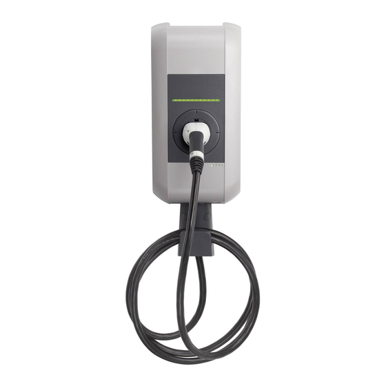
Variant overview Variant overview Base model with socket (Type 2)… [A]…Status LED [B]…Standard socket (variants possible) [C]…Housing cover Base model with charging cable Type 1, Type 2)… [A]…Status LED [B]…Parking bay for charging connector [C]…Housing cover [D]…Bracket for charging cable Storing the charging connector/charging cable…... - Page 10 Variant overview RFID sensor The RFID sensor [R] is used for touchless authoriza- tion of a user with MIFARE cards or tags according to ISO14443. Key switch The key switch [S] is used for authorizing a user with a key. Additional optional equipment ●...
-
Page 11: Installation Guidelines
Installation guidelines Installation guidelines General criteria for the site selection The charging station was constructed for the indoor and outdoor area. Accordingly it is necessary to ensure the installation conditions and the protection of the device at the installation site. ●... -
Page 12: Specifications For The Electrical Connection
Installation guidelines Specifications for the electrical connection 3.2.1 General The charging station is set to 10 amps in the delivery state. Set the maximum current using the DIP switches to match the installed line circuit breaker (see Chapter "↪ 4.6 DIP switch settings [31]"). -
Page 13: Differing Z.e.-Ready / E.v. Ready Requirements
Installation guidelines 3.2.2 Differing Z.E.-Ready / E.V. Ready requirements ● In the event that the internal switching element (contactor) is no longer able to open, an additional switch-off capability must be realized. This can be realized with the switch contact output [X2] (for details see Chapter "↪... -
Page 14: Space Requirements
Installation guidelines Space requirements Space requirement… For device versions with optional cable hanger, addi- tional free area y for the charging cable to be used is to be accounted for. If several charging stations are installed adjacent to each other, a distance of at least 200 mm between charging stations must be complied with. -
Page 15: Installation
Installation Installation Scope of delivery e-series Others Charging station 1 pieces 1 pieces Cable hanger (for versions with charging cable) 1 pieces 1 pieces Installation manual (for the specialist) 1 pieces 1 pieces User manual (for the end customer) 1 pieces 1 pieces Drilling template 1 pieces... -
Page 16: Installation Requirements
Installation Installation requirements ● Before beginning the installation, the installation guidelines must be observed. ● Contact person on-site (for access to the mains disconnector in the electrical distribution panel board). ● The electrical connection (power supply line) must be prepared. ●... -
Page 17: Preparing The Housing
Installation Preparing the housing 4.2.1 Removing the housing cover Cover screws… Unscrew the two cover screws [S] on the bottom side of the housing cover. Removing the housing cover… (1) Pull the housing cover down slightly. (2) Slide the housing cover up slightly to unhinge it. 17/44... -
Page 18: Removing The Connector Panel Cover
Installation 4.2.2 Removing the connector panel cover Removing the connector panel cover Unscrew the four screws that mount the connector panel cover and remove the connector panel cover. Take the silica bag out of the terminal panel and dispose of it properly. Preparing the cable insertion There are two options available for the cable insertion: ●... -
Page 19: Cable Insertion From Above - Surface Cable Routing
Installation 4.3.1 Cable insertion from above - surface cable routing ... Cable gland M32 (power supply line) ... Cable gland M16 (for control line/Ethernet) ... Cable gland M16 (for control line/Ethernet) 4.3.2 Cable insertion from behind - flush-mounted cable routing ... -
Page 20: Mounting The Charging Station
Depending on the device model or for special materials, the installation materials must be provided by the customer. A proper installation is absolutely necessary and lies outside of the scope of re- sponsibility of the KEBA AG. Please also observe the following manufacturer instructions: Instructions for placing anchors and bolts. - Page 21 Installation Water drainage The water drainage from the top side to the rear side of the charging station must be ensured. Therefore, ob- serve the following: ● Only a vertical installation of the charging station is permitted. ● The charging station must be mounted at an angle of 90°...
-
Page 22: Electrical Connection
Installation Electrical connection 4.5.1 Connection overview with opened connector panel cover ... Mains connection phase conductor 1 ... Service button ... Mains connection phase conductor 2 ... Status LED (internal) ... Mains connection phase conductor 3 ... Enable input ... Mains connection N conductor ... -
Page 23: Connecting The Power Supply Line
Installation 4.5.2 Connecting the power supply line Running the power supply line (surface cable rout- ing) Run the supply line from ABOVE as shown in the figure. [M]… Cable sheathing Running the power supply line (flush-type cable routing) The power supply cable must be run as shown through the feedthrough/double-membrane seal [DMS]. - Page 24 Installation Connecting the power supply line Shorten the connection wires to the appropriate length; these should be kept as short as possible. The PE conductor must be longer than the remain- ing conductors! Strip approx.12 mm from the connection wires. Core-end sleeves are recommended for fine stranded wires.
- Page 25 Installation Opening the power supply terminal… Using moderate force, press the screwdriver straightly into the terminal until the contact opens completely. The angle of the screwdriver changes while press- ing in the terminal. Connecting wires… Insert the stripped connection wire into the power supply terminal.
-
Page 26: Enable Input [X1] (Excluding E-Series)
Installation 4.5.3 Enable input [X1] (excluding e-series) The enable input is equipped for use with a potential-free contact. Using the enable input, it is possible to control the charging station using external components (e.g. external key switches, ripple control receiver of the energy supplier, house control, time switches, combination lock, photovoltaic system etc.). -
Page 27: Switch Contact Output [X2] (Excluding E-Series)
Installation 4.5.4 Switch contact output [X2] (excluding e-series) The switch contact output (signal contact) is a potential-free relay contact and can be used as a charging status display (default) or contactor monitoring. Circuit diagram: ● Safety extra-low voltage Vcc < 50 V ●... -
Page 28: Terminals [X1/X2] (Excluding E-Series)
Installation Example (supplement to the circuit diagram): The switch contact output can be used to switch off the charging station (disconnect the current) by means of an overriding disconnect solution..Main switch ... Line circuit breaker + RCD circuit breaker ... -
Page 29: Ethernet1 Connection [Eth] (Optional)
Installation 4.5.6 Ethernet1 connection [ETH] (optional) WARNING! Danger from compensation currents on shielding! Compensation currents flowing through shielding in extended systems can lead to damage to the interfaces and hazards when working on the data lines. ● Any measures (such as connecting to a shared distribution board, expanding a TN-S network, etc.) should be discussed with the person responsible for building services. - Page 30 Installation LSA+® insertion tool Original KRONE insertion tool with solder-free and stripping-free connection of the wires and simultaneous trimming of the residual lengths. Preparing the connection cable Strip the connection cable approximately 6 cm. Fold back approx. 1 cm of shielded braiding com- pletely and wrap it with conductive adhesive textile tape.
-
Page 31: Dip Switch Settings
Installation DIP switch settings Changes to the DIP switch settings only become effective after a restart of the charging station! To do this, press the [service button] for 1 second or switch the power supply voltage off/on. DIP switches… The DIP switches are used for the addressing and con- figuring the charging station and are located under the connector panel cover. - Page 32 Installation Only one maximum value, which is smaller or equal to the operating current according to the type plate, can be set with the following DIP switches: SETTING THE AMPERAGE (DSW1) (*1) Current DIP-Switch Figure D1.6 D1.7 D1.8 (*1) Preset maximum charging current value for the vehicle (Control Pilot Duty Cycle). OBTAIN IP ADDRESS VIA DHCP (NO ADDRESSING) (*2) DSW2.1 to DSW2.4=OFF / DSW2.5=OFF / DSW2.6=OFF The charging procedure in STANDARD mode is carried out automati-...
- Page 33 Installation USE FIXED IP ADDRESS (*2) DSW2.1 to DSW2.4 / DSW2.5=OFF / DSW2.6=ON Since multiple charging stations are located in a network; the charging stations must be addressed. Addressing is done using the DIP switches DSW2.1 to DSW2.4. The settable Ethernet addresses start at 10 + DIP switch setting. With 4-bit addressing, the addresses 11 to 26 can be used Example for address "17": [192.168.25.xx].
-
Page 34: Commissioning
Installation Commissioning General commissioning process 1) Remove all residual installation and connection materials from the connection area. 2) Before commissioning, check all screw and terminal connections for tightness. 3) Check whether all unused cable screw connections are properly sealed with blind plugs or dummy screw fittings. -
Page 35: Safety Checks
Installation 4.7.2 Safety checks Before the initial use, check the effectiveness of the safety measure(s) of the system according to the nation- ally applicable regulations (e.g.:ÖVE/ÖNORM E8001-6-61, DIN VDE 0100-600:2008-06 "Checks,...")! Electrical systems or devices must be checked by the installer of the system or device before their initial op- eration. -
Page 36: Mounting The Connector Panel Cover
Installation 4.7.4 Mounting the connector panel cover Mounting the connector panel cover Insert the connector panel cover again. Mount the connector panel cover again using the four screws. Enclosure marking Tighten the 4 screws until the enclosure marking on the connector panel cover is flush with the enclo- sure. -
Page 37: Mounting The Housing Cover
Installation 4.7.5 Mounting the housing cover Fitting the housing cover… Fit the housing cover at the top and push the cover downwards slightly. Make sure that the housing cover is seated cor- rectly at the top in the housing guides. Mounting the housing cover…... -
Page 38: Additional Technical Instructions
Additional technical instructions Additional technical instructions Programming RFID cards (optional) Note If you have a device version with RFID function, then please follow the programming instructions in the "Authorization functions" manual. Communication with the electric vehicle PLC->Ethernet (optional; P20 only) To grant the vehicle access to the home network or the Internet, the powerline communication between vehi- cle and charging station must be configured on both sides using the same password (NMK "Network Mem- bership Key"). -
Page 39: Dimensions
Additional technical instructions Dimensions Version with standard socket (Type 2) Figure 5-1: Dimensions in millimeters 39/44... -
Page 40: Technical Data
Additional technical instructions Technical data Electrical data Cable feed: Surface cable routing or flush-type cable routing Connection cross-section: Minimum cross-section (depending on the cable and the laying system): - 5 x 2.5 mm² (16 A nominal current) - 5 x 6.0 mm² (32 A nominal current) Supply terminals: Connection line: - Solid (min.-max): 0.2 –... - Page 41 Additional technical instructions Interfaces Enable input [X1]: Enable input for external authorization: Connection line: - Cross section (min.-max): 0.08 – 4 mm² - AWG (min.-max): 28 – 12 Potential-free switch contact output [X2]: Safety extra-low voltage <50 V 50/60 Hz External current limiting max.
-
Page 42: Ce Declaration Of Conformity
Additional technical instructions CE Declaration of Conformity KEBA hereby declares that the products KeContact P20 and KeContact P30 comply with the following Direc- tives: 2004/108/EC Directive on electromagnetic compatibility 2006/95/EC Low-voltage Directive 2011/65/EU Directive on the restriction of the use of certain hazardous substances (RoHS) -
Page 43: Index
Index Index Cable feed from the rear ........ 19 Line circuit breaker .......... 12 Cable insertion from above - surface cable routing . 19 Mains disconnector .......... 12 CE Declaration ........... 42 Mounting the charging station ...... 20 Charging station with charging cable .... 9 Mounting the connector panel cover .... - Page 44 www.kecontact.com...
Need help?
Do you have a question about the KeContact P20 and is the answer not in the manual?
Questions and answers