Burster DIGIFORCE 9307 Operation Manuals
Profibus manual
Hide thumbs
Also See for DIGIFORCE 9307:
- Operation manual (503 pages) ,
- Operation manual (154 pages) ,
- Operation manual (205 pages)
Table of Contents
Advertisement
Quick Links
Download this manual
See also:
Operating Manual
© 2015
burster präzisionsmesstechnik gmbh & co kg
All rights reserved
Valid from: 30.07.2015
Applies to: DIGIFORCE
OPERATION MANUAL
DIGIFORCE
PROFIBUS Manual
®
9307 Vxxx2
®
9307
Manufacturer:
burster präzisionsmesstechnik gmbh & co kg
Talstraße 1 – 5
76593 Gernsbach
Germany
Tel.:
(+49) 07224 / 6450
Fax.:
(+49) 07224 / 64588
E-Mail:
info@burster.com
www.burster.com
1957-BA9307PROFIEN-5170-071521
Postbox 1432
76587 Gernsbach
Germany
Advertisement
Table of Contents

Related Manuals for Burster DIGIFORCE 9307


Summary of Contents for Burster DIGIFORCE 9307
- Page 1 OPERATION MANUAL ® DIGIFORCE 9307 PROFIBUS Manual © 2015 Manufacturer: burster präzisionsmesstechnik gmbh & co kg burster präzisionsmesstechnik gmbh & co kg All rights reserved Talstraße 1 – 5 Postbox 1432 76593 Gernsbach 76587 Gernsbach Germany Germany Valid from: 30.07.2015 ®...
- Page 2 (hereinafter referred to as "product") are the results of targeted development and meticulous research. As of the date of delivery, burster provides a warranty for the proper condition and functioning of these products covering material and production defects for the period specified in the warranty document accompanying the product.
-
Page 3: Table Of Contents
Table of contents Symbols, notes and abbreviations ................9 Safety symbols ...................... 9 Notes and infos ..................... 9 Abbreviations ....................... 10 Introduction ........................ 11 General safety instructions .................. 11 Intended use ......................12 Technical Data ......................13 PROFIBUS DP system data ................13 Model 9307 device data .................. - Page 4 PROFIBUS DP Data Protocol ..................23 Meaning of the contents of the different protocol modes ........23 PLC inputs - Transfer from master to slave ............24 6.2.1 PLC inputs Byte 1 (master to slave) ............24 6.2.2 PLC inputs Byte 2 (master to slave) ............24 6.2.3 PLC inputs Byte 3 (master to slave) ............
- Page 5 7.4.4 Minimal setup menue (Slot 33) .............. 60 7.4.5 General channel settings (Slot 34) ............61 7.4.6 Channel settings "Potentiometer" (Slot 35) ..........66 7.4.7 Channel settings "Standard signal" (Slot 36) ......... 66 7.4.8 Channel settings "Strain gauge" (Slot 37) ..........66 7.4.9 Channel settings "Resistance"...
- Page 6 7.4.39 Tolerance band for evaluation elements (Slot 76) ........ 112 7.4.40 Realtime switchpoints S1 (Slot 77) ............112 7.4.41 Realtime switchpoints S2 (Slot 78) ............113 7.4.42 Realtime switchpoints S3 (Slot 79) ............113 7.4.43 Realtime switchpoints S4 (Slot 80) ............114 7.4.44 Sensor test (Slot 81) ................
- Page 7 7.5.22 Statistic measurement result evaluation element trapezoid window X2 (EvElem16) ..................130 7.5.23 Statistic measurement result evaluation element trapezoid window Y1 (EvElem17) ..................130 7.5.24 Statistic measurement result evaluation element trapezoid window Y2 (EvElem18) ..................130 7.5.25 Statistic measurement result evaluation element envelope 1 (EvElem19)130 7.5.26 Statistic measurement result evaluation element envelope 2 (EvElem20)130 7.5.27...
- Page 8 7.5.51 Evaluation results threshold 3 .............. 139 7.5.52 Evaluation results threshold 4 .............. 139 7.5.53 Evaluation results trapezoid window X 1 ..........140 7.5.54 Evaluation results trapezoid window X 2 ..........140 7.5.55 Evaluation results trapezoid window Y 1 ..........140 7.5.56 Evaluation results trapezoid window Y 2 ..........
-
Page 9: Symbols, Notes And Abbreviations
1 Symbols, notes and abbreviations 1.1 Safety symbols On the device and in this manual the following symbols warn about risks: Symbols in this manual Notice A property damage can result if proper precautions are not taken Warning A property damage and a severe personal injury or death can result if proper precautions are not taken.. -
Page 10: Abbreviations
1.3 Abbreviations Bus error DGND Data transfer potential (reference potential to VP) Device description data PROFIBUS and PROFINET International (user organization) Request To Send RxD/TxD-N Receive/Transmit Data -N, A-line RxD/TxD-P Receive/Transmit Data -P, B-line Positive supply voltage (+5 V) for the terminating resistors of 175... -
Page 11: Introduction
2 Introduction 2.1 General safety instructions Warning concerning installation of the device and software • Installation of the device and the interface must be carried out by qualified personnel only. Qualified personnel meets the following requirements: You are familiar with the safety designs used in automation engineering, and understand how to deal with them in your capacity as configuration engineer. -
Page 12: Intended Use
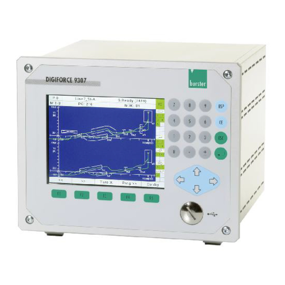
2.2 Intended use ® The DIGIFORCE 9307 is an instrument for monitoring repetitive production processes. Its core function is to record and analyze signals from processes in which physical variables, such as force, pressure or torque, vary as a function of displacement, angle or time according to a defined curve. The resultant measurement curve is analyzed using graphical evaluation elements such as windows, envelopes and thresholds. -
Page 13: Technical Data
3 Technical Data 3.1 PROFIBUS DP system data Number of devices or modules 126 with repeaters Transmission medium Cu cable to IEC 61158 Max. bus segment length 100 m to 1200 m (dependent on baud rate/cable) Data transfer rates 9.6 kBaud to 12 MBaud (dependent on cable) You will find further information about PROFIBUS DP at: www.profibus.com. -
Page 14: Electromagnetic Compatibility
EN 61000-3-3:1995+A1:2001 3.5 Notes on CE labeling burster equipment carrying the CE mark meets the requirements of the EU directives and the harmonized European standards (EN) cited therein. The EU declarations of conformity are available to the relevant authorities as specified in the directives. -
Page 15: Installation
Please note that you can download various documents such as installation guidelines and specifications about PROFIBUS at PI: www.profibus.com. 4.1 Connection of fieldbus lines burster devices with a PROFIBUS option have a 9-pin SUB-D female connector for the fieldbus connection. Meaning... -
Page 16: Parameter Value
4.2.1 Parameter value 135 to 165 for 3 to 30 Mhz Characteristic impedance in Ω Effective capacitance < 30 pF/m < 110 Loop impedance (Ω/km) Wire diameter (mm) *) > 0.64 Wire cross-section (mm2) > 0.34 *) The wire cross-sections used must be suitable for the connection options on the bus connector.For cable type A, the maximum cable lengths for a bus segment depend on the transfer rate. -
Page 17: Configuring A Profibus.dp System
4.3 Configuring a PROFIBUS.DP system System configuration PROFIBUS configurator Device master data files GSD files PROFIBUS-DP Field Drive Field device module device burster burster 9310 9307 of 175... -
Page 18: Configuration Menue In Digiforce ® 9307
® 4.4 Configuration menue in DIGIFORCE 9307 To access the menue Start in measurement mode. After power on the measurement mode is always set. The display will look differently dependent on your settings or your last measurements. You can go to "Main setup menue" in measurement mode by pressing the [F5] key twice. In measurement mode, press the [F5] key twice. - Page 19 Select "PROFIBUS fieldbus Setup" menue with ▼ or ▲ and press [Enter]. Parameters Station address Enter the PROFIBUS address for the unit here. Valid address range: 1 … 126 ® Control via PROFIBUS: DIGIFORCE 9307 responds solely to control signals (inputs) on the PROFIBUS interface ®...
-
Page 20: Profibus
5 PROFIBUS 5.1 Overview PROFIBUS PROFIBUS was developed as an open fieldbus. It was standardized in the German standard DIN 19 245 and was later standardized in IEC 61158. PROFIBUS is a medium for pure data transfer, like the RS232 standard for instance. There are two different types of communication •... -
Page 21: General Information On Profibus Data Transfer
In general, retrieving 240 bytes from a slave is too long for the user because it makes the total cycle time too long. This is why different modified response lengths (see chapter 6.1 Meaning of the ® contents of the different protocol modes on page 23) are provided in the DIGIFORCE 9307 unit. -
Page 22: Data Conversion
5.4 Data conversion 5.4.1 Description of the data formats in this manual Data transfer for the various modes is described below. The terms PLC inputs and PLC outputs refer to the DIGIFORCE 9307 unit. These terms are reversed when referred to the master. The function of the PLC-In / PLC-Out bits is identical to the parallel PLC I/O ports on the unit itself and ... -
Page 23: Profibus Dp Data Protocol
6 PROFIBUS DP Data Protocol 6.1 Meaning of the contents of the different protocol modes Overview of the available PROFIBUS DP modes: Mode Contents Length/bytes bytes PLC output status ∑ 8 bytes Evaluation info PLC output status Evaluation info ∑ 56 bytes 12 evaluation values (float), selectable list M5-1* 12x4 PLC output status... -
Page 24: Plc Inputs - Transfer From Master To Slave
The live values of the sensor channels are updated at a rate of 100 Hz. The values are only updated ® when the DIGIFORCE 9307 is ready to record measurements or is actively taking a measurement. How to define the selectable list: The parameterization of the selectable lists is done in the main setup menue "Setup user defined values"... -
Page 25: Plc Inputs Byte 3 (Master To Slave)
6.2.3 PLC inputs Byte 3 (master to slave) PLC inputs Byte 3 (Master Slave) Valid values: IN_RESET Bit 0 LSB IN_PROG6* Bit 1 Set reserved bits to '0' IN_STEST Bit 2 IN_PROG5* Bit 3 IN_LTEST Bit 4 IN_TAREX Bit 5 IN_TAREY1 Bit 6 IN_TAREY2... -
Page 26: Plc Outputs - Transfer From Slave To Master
6.3 PLC outputs - Transfer from slave to master The data refers to the PLC output of the DIGIFORCE 9307. The data described here is the data ® transferred from the DIGIFORCE 9307 to the PROFIBUS master. The function of the PLC-In / PLC-Out bits is identical to the parallel PLC I/O ports on the unit itself and ®... -
Page 27: Plc Outputs Byte 3 (9307 Adjustable Outputs)
6.3.3 PLC outputs Byte 3 (9307 adjustable outputs) PLC outputs Byte 3 (Slave Master) Valid values: PLC_OUT9 Bit 0 LSB PLC_OUT10 Bit 1 PLC_OUT11 Bit 2 PLC_OUT12 Bit 3 PLC_OUT13 Bit 4 PLC_OUT14 Bit 5 PLC_OUT15 Bit 6 PLC_OUT16 Bit 7 MSB 6.3.4 PLC outputs Byte 4 (9307 adjustable outputs) -
Page 28: Evaluation Info
9307 adjustable PLC outputs default assignment PLC_OUT5 OUT_PROG1 PLC_OUT6 OUT_PROG2 PLC_OUT7 OUT_PROG3 PLC_OUT8 OUT_PROG4 PLC_OUT9 OUT_S3 PLC_OUT10 OUT_S4 PLC_OUT11 OUT_NOK_WINDOW_8 PLC_OUT12 OUT_NOK_WINDOW_7 PLC_OUT13 OUT_NOK_WINDOW_6 PLC_OUT14 OUT_NOK_WINDOW_5 PLC_OUT15 OUT_NOK_WINDOW_4 PLC_OUT16 OUT_NOK_WINDOW_3 PLC_OUT17 OUT_NOK_WINDOW_2 PLC_OUT18 OUT_NOK_WINDOW_1 PLC_OUT19 OUT_WARNING_TARE PLC_OUT20 OUT_WARNING_TOOLCOUNT PLC_OUT21 OUT_WARNING_TOTAL PLC_OUT22 OUT_TEST_OP_SIMPLE PLC_OUT23... -
Page 29: Evaluation Info Byte 2
6.4.2 Evaluation info Byte 2 Evaluation info Byte 2 (Slave Master) Valid values: Threshold_3_NOK Bit 0 LSB Threshold_4_NOK Bit 1 Envelope_1_NOK Bit 2 Envelope_2_NOK Bit 3 Math_Evaluation_1_NOK Bit 4 Math_Evaluation_2_NOK Bit 5 Math_Evaluation_3_NOK Bit 6 Math_Evaluation_4_NOK Bit 7 MSB 6.4.3 Evaluation info Byte 3 Evaluation info Byte 3 (Slave ... -
Page 30: Byte Reference List
6.5 Byte reference list 6.5.1 Mode 1 Data from master to slave Byte Function Section Comments PLC inputs Byte 1 6.2.1 PLC inputs Byte 2 6.2.2 PLC inputs Byte 3 6.2.3 PLC inputs Byte 4 6.2.4 Data from slave to master Byte Function Section... - Page 31 Byte Function Section Comments Evaluation info Byte 1 6.4.1 Evaluation info Byte 2 6.4.2 Evaluation info Byte 3 6.4.3 Evaluation info Byte 4 6.4.4 ® M5-1 value_1 (1st Byte) see DIGIFORCE User defined value 9307 operation in DIGIFORCE® 9307 manual chapter 5.13 List M5-1 (32-Bit float) M5-1 value_1 (2nd Byte) see above...
-
Page 32: Mode 3
Byte Function Section Comments M5-1 value_8 (1st Byte) see above User defined value in DIGIFORCE® 9307 M5-1 value_8 (2nd Byte) see above List M5-1 (32-Bit float) M5-1 value_8 (3rd Byte) see above M5-1 value_8 (4th Byte) see above M5-1 value_9 (1st Byte) see above User defined value in DIGIFORCE®... - Page 33 Data from slave to master Byte Function Section Comments PLC outputs Byte 1 6.3.1 PLC outputs Byte 2 6.3.2 PLC outputs Byte 3 6.3.3 PLC outputs Byte 4 6.3.4 Evaluation info Byte 1 6.4.1 Evaluation info Byte 2 6.4.2 Evaluation info Byte 3 6.4.3 Evaluation info Byte 4 6.4.4...
- Page 34 Byte Function Section Comments M5-1 value_6 (4th Byte) see above M5-1 value_7 (1st Byte) see above User defined value in DIGIFORCE® 9307 M5-1 value_7 (2nd Byte) see above List M5-1 (32-Bit float) M5-1 value_7 (3rd Byte) see above M5-1 value_7 (4th Byte) see above M5-1 value_8 (1st Byte) see above...
- Page 35 Byte Function Section Comments in DIGIFORCE® 9307 M5-2 value_3 (2nd Byte) see above List M5-2 (32-Bit float) M5-2 value_3 (3rd Byte) see above M5-2 value_3 (4th Byte) see above M5-2 value_4 (1st Byte) see above User defined value in DIGIFORCE® 9307 M5-2 value_4 (2nd Byte) see above List M5-2 (32-Bit float)
-
Page 36: Mode 4
Byte Function Section Comments M5-2 value_11 (4th Byte) see above M5-2 value_12 (1st Byte) see above User defined value in DIGIFORCE® 9307 M5-2 value_12 (2nd Byte) see above List M5-2 (32-Bit float) M5-2 value_12 (3rd Byte) see above M5-2 value_12 (4th Byte) see above 6.5.4 Mode 4... - Page 37 Byte Function Section Comments ® DIGIFORCE 9307 M5-1 value_3 (2 Byte) see above List M5-1 M5-1 value_3 (3 Byte) see above (32-Bit float) M5-1 value_3 (4 Byte) see above M5-1 value_4 (1 Byte) see above User defined value in ® DIGIFORCE 9307 M5-1 value_4 (2...
- Page 38 Byte Function Section Comments M5-1 value_11 (4 Byte) see above (32-Bit float) M5-1 value_12 (1 Byte) see above User defined value in ® DIGIFORCE 9307 M5-1 value_12 (2 Byte) see above List M5-1 M5-1 value_12 (3 Byte) see above (32-Bit float) M5-1 value_12 (4 Byte) see above...
- Page 39 Byte Function Section Comments ® DIGIFORCE 9307 M5-2 value_8 (2 Byte) see above List M5-2 M5-2 value_8 (3 Byte) see above (32-Bit float) M5-2 value_8 (4 Byte) see above M5-2 value_9 (1 Byte) see above User defined value in ® DIGIFORCE 9307 M5-2 value_9 (2...
-
Page 40: Mode 5
Byte Function Section Comments M1_Curvevalue_4 (4 Byte) see above (32-Bit float) M1_Curvevalue_5 (1 Byte) see above User defined value in ® DIGIFORCE 9307 M1_Curvevalue_5 (2 Byte) see above value in curve M1 M1_Curvevalue_5 (3 Byte) see above (32-Bit float) M1_Curvevalue_5 (4 Byte) see above M1_Curvevalue_6 (1... - Page 41 Byte Function Section Comments M5-1 value_2 (1 Byte) see above User defined value in ® DIGIFORCE 9307 M5-1 value_2 (2 Byte) see above List M5-1 M5-1 value_2 (3 Byte) see above (32-Bit float) M5-1 value_2 (4 Byte) see above M5-1 value_3 (1 Byte) see above User defined value in...
- Page 42 Byte Function Section Comments M5-1 value_10 (3 Byte) see above List M5-1 (32-Bit float) M5-1 value_10 (4 Byte) see above M5-1 value_11 (1 Byte) see above User defined value in ® DIGIFORCE 9307 M5-1 value_11 (2 Byte) see above List M5-1 M5-1 value_11 (3 Byte) see above...
- Page 43 Byte Function Section Comments M5-2 value_7 (1 Byte) see above User defined value in ® DIGIFORCE 9307 M5-2 value_7 (2 Byte) see above List M5-2 M5-2 value_7 (3 Byte) see above (32-Bit float) M5-2 value_7 (4 Byte) see above M5-2 value_8 (1 Byte) see above User defined value in...
- Page 44 Byte Function Section Comments M1_Curvevalue_3 (3 Byte) see above value in curve M1 (32-Bit float) M1_Curvevalue_3 (4 Byte) see above M1_Curvevalue_4 (1 Byte) see above User defined value in ® DIGIFORCE 9307 M1_Curvevalue_4 (2 Byte) see above value in curve M1 M1_Curvevalue_4 (3 Byte) see above...
-
Page 45: Acyclical Profibus Services
7 Acyclical PROFIBUS services The services are described from the point of view of the master. Len: for strings without terminating 0x0. 7.1 Indirect slot addressing, e.g. for Siemens S7 projects You can address the slot that you want directly if your PROFIBUS master can directly adress a selected slot (e.g. - Page 46 ® Example: DIGIFORCE 9307 enter station name (slot 30 / index 19 see 7.4.1 General settings (Slot 30)) Indirect slot addressing Enter the slot address of the desired slot into the address 1; in this case, address Enter slot no. into index ...
-
Page 47: Read And Write Curves Over Profibus (Acyclically)
7.2 Read and write curves over PROFIBUS (acyclically) It is possible to read or write at multiple slots in the slot index directory. The implementation is the same in both cases, and requires a structured procedure. 7.2.1 The curve is to be read. Load the curve into the fieldbus card through a write access to index 10. -
Page 48: The Curve Is To Be Written
7.2.2 The curve is to be written Query the curve index of the last point in the corresponding slot/index (e.g. 63/22, 68/22, 84/11, 84/12). The coordinate group that is to be written to is selected (e.g. 0 for values 0 ... 199) through a write access to index 19. -
Page 49: Slot - Index Tables
7.3 Slot - index tables 7.3.1 Indirect slot addressing If your PROFIBUS master in the DP-V1 service is not able to write/read arbitrary slot addresses (e.g. in the Siemens S7 environment), it is necessary to map the desired destination slot with the aid of indirect slot addressing. - Page 50 Slot Index Description Value Meaning of value Type Optional analog interface No option enabled Torque Piezo Torque+Piezo Resistance Torque+Resistance Piezo+Resistance Torque+Piezo+ Resistance Info: Calibration date 07.11.2012 analog interface 07.11.2012 Info: Calibration date optional analog interface Reserved Not possible Station name Stat14 right Tool counter 0 …...
- Page 51 Slot Index Description Value Meaning of value Type Measurement menue function key definition Meas. menue page up Meas. menue page down Meas. program incremental Meas. program decremental Tare X Tare Y Tare Y2 Measurement Start/Stop Acknowledge OK parts Acknowledge NOK parts Sensor test Reference measurement Edit mode...
- Page 52 Slot Index Description Value Meaning of value Type Measurement menue function key definition Meas. menue page up Meas. menue page down Meas. program incremental Meas. program decremental Tare X Tare Y Tare Y2 Measurement Start/Stop Acknowledge OK parts Acknowledge NOK parts Sensor test Reference measurement Edit mode...
- Page 53 Slot 30, Index 41 to 58 Slot Index Description Value Meaning of value Type Display the Y1 displaying meas. curves measurement menue, Y2 displaying meas. curves read the currently Y1 / Y2 displaying meas. curves displayed measurement General curve data Y1 menue General curve data Y2 Smiley, Pass/Fail display.
- Page 54 Slot Index Description Value Meaning of value Type Access authorisation Access level disabled USER DEFINED Access level enabled VALUES Access authorisation Access level disabled COPY PROGRAMS Access level enabled Reserved Master password 0000 … 9999 Set master password to EVENT! Writing an arbitrary byte initiates default action...
- Page 55 Slot Index Description Value Meaning of value Type PLC output 1 (Pin 2) Traffic light NOK (red) PLC output 1 (Pin 2) NOK window 1 PLC output 1 (Pin 2) NOK window 2 PLC output 1 (Pin 2) NOK window 3 PLC output 1 (Pin 2) NOK window 4 PLC output 1 (Pin 2)
- Page 56 Slot Index Description Value Meaning of value Type PLC output 1 (Pin 2) A5 (switch program.) (only if 128 MP) PLC output 1 (Pin 2) A6 (switch program) (only if 128 MP) PLC output 1 (Pin 2) OK channel Y1 PLC output 1 (Pin 2) OK channel Y2 Slot 30, Indices 60 to 81 (Assignment PLC outputs 2 to 23)
- Page 57 Slot 30, Indices 82 to 115 Slot Index Description Value Meaning of value Type Order sheet: Operator Michael_ Mueller Order sheet: Order AN_123456 number Order sheet: Batch BATCH_ 257-3 Order sheet: Component Cylinder_right SN_12345678 Order sheet: Serial number 1 Order sheet: Serial SN_98765432 number 2 Order sheet: Shift number...
- Page 58 Slot Index Description Value Meaning of value Type Order sheet: Shift counter 0 … read-out quantity of shift 3 4294967296 Order sheet: Shift counter 0 … read-out quantity of shift 4 4294967296 Order sheet: Shift counter 0 … 4294967296 read-out quantity of shift 5 Order sheet: Shift counter 0 …...
-
Page 59: Reserved (Slot 31)
Slot Index Description Value Meaning of value Type Acknowledgement 0 ... 10 10: max. volume function: Buzzer volume Update display (refresh Event! Writing an arbitrary byte view) initiates action 7.4.2 Reserved (Slot 31) Slot Index Description Value Meaning of value Type Reserved slot Not possible... -
Page 60: Minimal Setup Menue (Slot 33)
Slot Index Description Value Meaning of value Type Fault status of the internal 0x00000100 Invalid configuration U32x serial communication Fault status of the internal 0x00000200 Scaling fault U32x serial communication Fault status of the internal 0x00000400 No valid measurements U32x serial communication are available Fault status of the internal... -
Page 61: General Channel Settings (Slot 34)
7.4.5 General channel settings (Slot 34) Slot Index Description Value Meaning of value Type Not possible 1 - 9 Reserved slots Channel settings Terminals: channel X A, strain gauge A, Potentiometer Note: First make the A, standard signal settings in indices 10, 11, B, strain gauge 12, then initiate with index B, Potentiometer... - Page 62 Slot Index Description Value Meaning of value Type Channel settings Terminals: channel Y2 A, strain gauge A, Potentiometer Note: First make the A, standard signal settings in indices 10, 11, B, strain gauge 12, then initiate with index B, Potentiometer B, standard signal C, Incr.
- Page 63 Slot Index Description Value Meaning of value Type Filter channel Y2 5 Hz filter Note: Entry is not 10 Hz filter available for the channel 25 Hz filter settings "Time" and 50 Hz filter "Incremental" 100 Hz filter 200 Hz filter 400 Hz filter 800 Hz filter Transmitter supply...
- Page 64 Slot Index Description Value Meaning of value Type Set unit channel Y1 User defined unit 1 User defined unit 2 Note: Entry is not User defined unit 3 available for the channel settings "Time" and "Resistance". Set unit channel Y2 User defined unit 1 User defined unit 2 Note: Entry is not...
- Page 65 Slot Index Description Value Meaning of value Type Take the tare value for EVENT! channel Y1 and return the measured value Note: Entry is not available for the channel settings "Time", "Incremental" and "Resistance". Take the tare value for EVENT! channel Y2 and return the measured value Note: Entry is not...
-
Page 66: Channel Settings "Potentiometer" (Slot 35)
7.4.6 Channel settings "Potentiometer" (Slot 35) Slot Index Description Value Meaning of value Type Not possible 1 - 9 Reserved Potentiometer excitation 5 V excitation channel X 10 V excitation Potentiometer excitation 5 V excitation channel Y1 10 V excitation Potentiometer excitation 5 V excitation channel Y2... - Page 67 Slot Index Description Value Meaning of value Type Strain gauge input range 1 mV/V input range channel X 2 mV/V input range 4 mV/V input range 10 mV/V input range 20 mV/V input range 40 mV/V input range (40 mV/V are not allowed at 10 V excitation) Strain gauge input range 1 mV/V input range...
-
Page 68: Channel Settings "Resistance" (Slot 38)
Slot Index Description Value Meaning of value Type Strain gauge shunt channel Y1 10 kOhm 59 kOHM 80 kOHM 100 kOHM 300 kOHM Strain gauge shunt channel Y2 10 kOhm 59 kOHM 80 kOHM 100 kOHM 300 kOHM 7.4.9 Channel settings "Resistance" (Slot 38) Slot Index Description Value... -
Page 69: Channel Settings "Incremental" (Slot 40)
Slot Index Description Value Meaning of value Type Piezo input range 1nC range channel Y1 2nC range 5nC range 10nC range 20nC range 40nC range 80nC range 200nC range 400nC range 1uC range Piezo input range 1nC range channel Y2 2nC range 5nC range 10nC range... - Page 70 Slot Index Description Value Meaning of value Type Incremental reference reference mark off mark reference mark on channel Y2 reference mark distance coded Incremental set value at between Float value, reference mark - 9999999.0 Float according to channel X and 9999999.0 IEEE754 Incremental set value at between...
- Page 71 Slot Index Description Value Meaning of value Type Incremental between Float value, nominal increment - 9999999.0 Float according to channel X and 9999999.0 IEEE754 Incremental between Float value, nominal increment - 9999999.0 Float according to channel Y1 and 9999999.0 IEEE754 Incremental between Float value,...
-
Page 72: Channel Settings "Ssi" (Slot 41)
7.4.12 Channel settings "SSI" (Slot 41) Slot Index Description Value Meaning of value Type Not possible 1 .. 9 Reserved SSI sensor type Displacement sensor channel X Singleturn encoder Multiturn encoder Note: At the end, settings must be initiated through a write access to indices 37/38/39. - Page 73 Slot Index Description Value Meaning of value Type SSI format channel X Right aligned Tree Note: Only permitted for multiturn angle sensor! At the end, settings must be initiated through a write access to indices 37/38/39. SSI format channel Y1 Right aligned Tree Note: Only permitted for...
- Page 74 Slot Index Description Value Meaning of value Type SSI clock frequency 100 kHz channel X 200 kHz 1 MHz Note: At the end, settings must be initiated through a write access to indices 37/38/39. SSI clock frequency 100 kHz channel Y1 200 kHz 1 MHz Note: At the end, settings...
- Page 75 Slot Index Description Value Meaning of value Type SSI total number of bits 0 ... 48 Integer value channel X Note: At the end, settings must be initiated through a write access to indices 37/38/39. SSI total number of bits 0 ...
- Page 76 Slot Index Description Value Meaning of value Type SSI bit number rotations 0 ... 32 Integer value for multiturn angle channel X Note: At the end, settings must be initiated through a write access to indices 37/38/39. SSI bit number rotations 0 ...
-
Page 77: Channel Settings "Endat" (Slot 42)
7.4.13 Channel settings "EnDat" (Slot 42) Slot Index Description Value Meaning of value Type Not possible 1 .. 9 Reserved Read-out EnDat sensor EVENT! Writing an arbitrary byte data channel X initiates action Note: At the end, settings must be initiated through a write access to index 16. - Page 78 Slot Index Description Value Meaning of value Type EnDat clock frequency 100k Hz channel Y2 200 kHz 1 MHz Note: At the end, 2 MHz settings must be initiated through a write access to index 18. Copy EnDat sensor EVENT! Writing an arbitrary byte setup channel X initiates action...
- Page 79 Slot Index Description Value Meaning of value Type EnDat standard EnDat 2.1 channel Y1 EnDat 2.2 Note: See comment at the end of the slot. EnDat standard EnDat 2.1 channel Y2 EnDat 2.2 Note: See comment at the end of the slot. EnDat name of sensor "angle STR20...
- Page 80 Slot Index Description Value Meaning of value Type EnDat sensor serial SN1234567890 STR20 number channel Y2 Note: See comment at the end of the slot. EnDat sensor type Displacement STR20 channel X Singelturn encoder Multiturn encoder Note: See comment at the end of the slot.
- Page 81 Slot Index Description Value Meaning of value Type EnDat bit number 0 ... 32 Integer value displacement or angle singleturn channel Y1 Note: See comment at the end of the slot. EnDat bit number 0 ... 32 Integer value displacement or angle singleturn channel Y2 Note: See comment at the end of the slot.
- Page 82 Slot Index Description Value Meaning of value Type EnDat measuring length 16-Bit-Integer for displacement sensor value channel X Note: See comment at the end of the slot. EnDat measuring length 16-Bit-Integer for displacement sensor value channel Y1 Note: See comment at the end of the slot.
- Page 83 Slot Index Description Value Meaning of value Type EnDat max. clock 16-Bit-Integer frequency value channel Y1 Note: Only available with EnDat 2.2! See comment at the end of the slot. EnDat max. clock 16-Bit-Integer frequency value channel Y2 Note: Only available with EnDat 2.2! See comment at the end of the slot.
- Page 84 Slot Index Description Value Meaning of value Type 19 ... Comment on slots 19 … 54: Reading these entries only makes sense if the data has been read from the sensor beforehand (indices 10, 11, 12) It is also possible to write sensor data here.
-
Page 85: Tare (Slot 43)
7.4.14 Tare (Slot 43) Slot Index Description Value Meaning of value Type Not possible 1 .. 9 Reserved Tare at meas. start channel X Tare at meas. start channel Y1 Tare at meas. start channel Y2 Standard value for tare between Float value, channel X... -
Page 86: Measurement Mode (Slot 44)
Slot Index Description Value Meaning of value Type Tare channel Y1 EVENT! Writing an arbitrary byte initiates action Delete tare channel Y1 EVENT! Writing an arbitrary byte initiates action Tare channel Y2 EVENT! Writing an arbitrary byte initiates action Delete tare channel Y2 EVENT! Writing an arbitrary byte initiates action... - Page 87 Slot Index Description Value Meaning of value Type Set reference of curve Absolute Final force Note: "Underrun" is not Y1 reference line permitted if the channel overrun concerned is set to time. Y1 reference line underrun Y1 trigger overrun Y1 trigger underrun Y2 reference line overrun (not allowed when channel Y2 is off)
- Page 88 Slot Index Description Value Meaning of value Type Set start mode External X internal overrun X internal underrun Y1 internal overrun Y1 internal underrun Y2 internal overrun (not possible if Y2 is switched off) Y2 internal underrun (not possible if Y2 is switched off) Set stop mode External...
-
Page 89: Evaluation Window 1 (Slot 45)
Slot Index Description Value Meaning of value Type Set the "stop" number of 0 bis 5000 Integer value measured values Set bend-up factor between Float value -9999999.0 and Float according to 9999999.0 IEEE754 7.4.16 Evaluation window 1 (Slot 45) Slot Index Description Value Meaning of value... - Page 90 Slot Index Description Value Meaning of value Type Window 1 entry right Note: At the end, entry must be adopted through index 24. Window 1 entry bottom Note: At the end, entry must be adopted through index 24. Window 1 entry top Note: At the end, entry must be adopted through index 24.
- Page 91 Slot Index Description Value Meaning of value Type Window 1 online evaluation left - right right - left bottom - top top - bottom Window 1 1 or 2 online signal number Window 1 Low active Online signal level High active Window 1 Evaluate all passages "Evaluate only first...
-
Page 92: Evaluation Window 2 (Slot 46)
Slot Index Description Value Meaning of value Type Window 1 calculate gradient Window 1 calculate area under curve 7.4.17 Evaluation window 2 (Slot 46) Slot Index Description Value Meaning of value Type Not possible 1 .. 9 Reserved 10 ... See slot 45 7.4.18 Evaluation window 3 (Slot 47) Slot... -
Page 93: Evaluation Window 6 (Slot 50)
7.4.21 Evaluation window 6 (Slot 50) Slot Index Description Value Meaning of value Type Not possible 1 .. 9 Reserved 10 ... See slot 45 7.4.22 Evaluation window 7 (Slot 51) Slot Index Description Value Meaning of value Type Not possible 1 .. -
Page 94: Evaluation Trapezoid Window X1 (Slot 55)
7.4.26 Evaluation trapezoid window X1 (Slot 55) Slot Index Description Value Meaning of value Type Not possible 1 .. 9 Reserved 10 ... Trapezoid X1 off/on Trapezoid X1 between Float value limit Xmin -9999999.0 and Float according to 9999999.0 IEEE754 between Trapezoid X1 Float value... - Page 95 Slot Index Description Value Meaning of value Type Trapezoid X1 entry left Note: At the end, entry must be adopted through index 22. Trapezoid X1 entry right Note: At the end, entry must be adopted through index 22. Trapezoid X1 exit left Note: At the end, entry must be adopted...
-
Page 96: Evaluation Trapezoid Window X2 (Slot 56)
7.4.27 Evaluation trapezoid window X2 (Slot 56) Slot Index Description Value Meaning of value Type Not possible 1 .. 9 Reserved 10 ... See slot 55 7.4.28 Evaluation trapezoid window Y1 (Slot 57) Slot Index Description Value Meaning of value Type Not possible 1 .. - Page 97 Slot Index Description Value Meaning of value Type Trapezoid Y1 between Float value X limit bottom right -9999999.0 and Float according to 9999999.0 IEEE754 Note: At the end, entry must be adopted through index 17. Trapezoid Y1 EVENT Writing an arbitrary byte copy limits initiates action Note: Values entered...
-
Page 98: Evaluation Trapezoid Window Y2 (Slot 58)
Slot Index Description Value Meaning of value Type Trapezoid Y1 Forward Return Curve segment for Complete curve evalutation Trapezoid Y1 Evaluate all passages "Evaluate only first (like 9310) passage" Evaluate only first passages (like 9306) Trapezoid Y1 Channel Y1 channel Y1/Y2 Channel Y2 7.4.29 Evaluation trapezoid window Y2 (Slot 58) Slot... - Page 99 Slot Index Description Value Meaning of value Type Threshold 1 limit between Float value -9999999.0 and Float according to For type X: Ymax 9999999.0 IEEE754 For type Y: Xmax Note: At the end, entry must be adopted through index 15. Threshold 1 EVENT Writing an arbitrary byte...
- Page 100 Slot Index Description Value Meaning of value Type Threshold 1 Calculate bend Note: Only for type Y Threshold 1 between Float value 0.0 and Float according to Delta gradient for bend 9999999.0 IEEE754 Threshold 1 between Float value 0.0 and Float according to Delta Y bend 9999999.0...
-
Page 101: Evaluation Threshold 2 (Slot 60)
Slot Index Description Value Meaning of value Type Threshold 1 Calculate gradient Note: Only for type Y Threshold 1 Calculate area Note: Only for type Y 7.4.31 Evaluation threshold 2 (Slot 60) Slot Index Description Value Meaning of value Type Not possible 1 .. -
Page 102: Evaluation Rotary Switch 1 (Slot 73)
7.4.36 Evaluation rotary switch 1 (Slot 73) Slot/index data on request 7.4.37 Evaluation rotary switch 2 (Slot 74) Slot/index data on request 7.4.38 Evaluation mathematical functions (Slot 75) Slot Index Description Value Meaning of value Type Not possible 1 .. 9 Reserved Math. - Page 103 Slot Index Description Value Meaning of value Type Math. function Integer value See operand table in appendix formula row 1 operand A Note: At the end, entry must be adopted through index 23. Math. function Sum up Subtract formula row 1 Multiply operator Divide...
- Page 104 Slot Index Description Value Meaning of value Type Math. function EVENT Writing an arbitrary byte initiates action Copy formula 2 Note: Values entered into indices 24 - 26 are adopted Math. function Integer value See operand table in appendix formula row 3 operand A Note: At the end, entry must be adopted...
- Page 105 Slot Index Description Value Meaning of value Type Math. function Integer value See operand table in appendix formula row 4 operand B Note: At the end, entry must be adopted through index 35. Math. function EVENT Writing an arbitrary byte initiates action Copy formula 4 Note: Values entered...
- Page 106 Slot Index Description Value Meaning of value Type Math. function Sum up Subtract formula row 6 Multiply operator Divide Note: At the end, entry must be adopted through index 43. Math. function Integer value See operand table in appendix formula row 6 operand B Note: At the end, entry must be adopted...
- Page 107 Slot Index Description Value Meaning of value Type Math. function Integer value See operand table in appendix formula row 8 operand A Note: At the end, entry must be adopted through index 51. Math. function Sum up Subtract formula row 8 Multiply operator Divide...
- Page 108 Slot Index Description Value Meaning of value Type Math. function EVENT Writing an arbitrary byte initiates action Copy formula 9 Note: Values entered into indices 52 - 54 are adopted. Math. function Integer value See operand table in appendix formula row 10 operand A Note: At the end, entry must be adopted...
- Page 109 Slot Index Description Value Meaning of value Type Math. function between Float value -9999999.0 and Float according to Evaluation operand 1 9999999.0 IEEE754 Max. tolerance limit Note: At the end, entry must be adopted through index 63. Math. function EVENT Writing an arbitrary byte initiates action Copy evaluation1...
- Page 110 Slot Index Description Value Meaning of value Type Math. function between Float value -9999999.0 and Float according to Evaluation operand 3 9999999.0 IEEE754 Min. tolerance limit Note: At the end, entry must be adopted through index 71. Math. function between Float value -9999999.0 and Float according to...
- Page 111 Slot Index Description Value Meaning of value Type Math. function Integer value See operand table in appendix Evaluation operand 5 Note: At the end, entry must be adopted through index 79. Math. function between Float value -9999999.0 and Float according to Evaluation operand 5 9999999.0 IEEE754...
-
Page 112: Tolerance Band For Evaluation Elements (Slot 76)
Slot Index Description Value Meaning of value Type Math. function EVENT Writing an arbitrary byte initiates action Copy evaluation 6 Note: Values entered into indices 80 - 82 are adopted. 7.4.39 Tolerance band for evaluation elements (Slot 76) Slot Index Description Value Meaning of value Type... -
Page 113: Realtime Switchpoints S2 (Slot 78)
Slot Index Description Value Meaning of value Type Switchpoint S1 Channel X channel Channel Y1 Note: At the end, entry Channel Y2 must be adopted through index 14. Switchpoint S1 Low active level High active Note: At the end, entry must be adopted through index 14. -
Page 114: Realtime Switchpoints S4 (Slot 80)
7.4.43 Realtime switchpoints S4 (Slot 80) Slot Index Description Value Meaning of value Type Not possible 1 .. 9 Reserved 10.. See slot 77 7.4.44 Sensor test (Slot 81) Slot Index Description Value Meaning of value Type Not possible 1 .. 9 Reserved Sensor test Channel X on/off... -
Page 115: Setup User-Defined Values (Slot 82)
Slot Index Description Value Meaning of value Type Sensor test between Float value 0.0 and Float according to Channel Y1 allowed 9999999.0 IEEE754 deviation Sensor test between Float value 0.0 and Float according to Channel Y2 allowed 9999999.0 IEEE754 deviation Sensor test between Float value... - Page 116 Slot Index Description Value Meaning of value Type User-defined values Integer value See operand table in appendix value 10 User-defined values Integer value See operand table in appendix value 11 User-defined values Integer value See operand table in appendix value 12 User-defined values Integer value See operand table in...
-
Page 117: Copy/Initialize Measurement Programs (Slot 83)
Slot Index Description Value Meaning of value Type User-defined values Integer value See operand table in appendix value 27 User-defined values Integer value See operand table in appendix value 28 User-defined values Integer value See operand table in appendix value 29 User-defined values Integer value See operand table in... -
Page 118: Reference Curve Y1, Y2 (Slot 84
Slot Index Description Value Meaning of value Type Initialize selected EVENT Writing an arbitrary byte programs initiates action Note: Initializing according to indices 11 - Initialize all EVENT Writing an arbitrary byte measurement programs initiates action 7.4.47 Reference curve Y1, Y2 (Slot 84..88) Slot/index data on request 7.4.48 Test operation (Slot 89) Slot... - Page 119 Slot Index Description Value Meaning of value Type Fix scale Ymin channel Float value Float according to IEEE754 Note: At the end, entry must be adopted through index 15. Fix scale Ymax channel Float value Float according to IEEE754 Note: At the end, entry must be adopted through index 15.
-
Page 120: Reserved Slots
7.4.50 Reserved slots Slot Index Description Value Meaning of value Type 91… Not possible 7.5 Slot - index tables measurement results 7.5.1 Status of measurement Slot Index Description Value Meaning of value Type Not possible 1…9 Reserved Index of the last 16 Bit Integer 0 means that there is no measured value of the... -
Page 121: Further Informationen For Current Pretrigger Curve
Slot Index Description Value Meaning of value Type Evaluation channel Y2 Index of the curve´s 16 Bit Integer return point value Caution: The number of the pair of values is shown on the display. The index begins at 0, the number at 1! Index of the last 16 Bit Integer measured value of the... -
Page 122: General Curve Data Channel Y1
Slot Index Description Value Meaning of value Type Index of first pretrigger 0…255 Integer value between value (0…255) 0…255 Index of first pretrigger 0…255 Integer value between value (0…255) 0…255 7.5.4 General curve data channel Y1 Slot Index Description Value Meaning of value Type Not possible... -
Page 123: General Curve Data Channel Y2
7.5.5 General curve data channel Y2 Slot Index Description Value Meaning of value Type Not possible 1…9 Reserved See slot 103 7.5.6 Request measurement results of user-defined values Slot Index Description Value Meaning of value Type Not possible 1…9 Reserved User-defined value 1 String with the Designator = "0"... - Page 124 Slot Index Description Value Meaning of value Type User-defined value 4 String with max. STR4 unit 4 characters, e.g. "N" or "inch" User-defined value 5 String with the Designator = "0" means STR16 name designator of that no value is defined the value for this value number User-defined value 5...
- Page 125 Slot Index Description Value Meaning of value Type User-defined value 10 String with the Designator = "0" means STR16 name designator of that no value is defined the value for this value number User-defined value 10 Float value Float according to measurement value IEEE754 String with max.
- Page 126 Slot Index Description Value Meaning of value Type User-defined value 15 Float value Float according to measurement value IEEE754 User-defined value 15 String with max. STR4 unit 4 characters, e.g. "N" or "inch" String with the User-defined value 16 Designator = "0" means STR16 name designator of...
- Page 127 Slot Index Description Value Meaning of value Type User-defined value 20 String with max. STR4 unit 4 characters, e.g. "N" or "inch" User-defined value 21 String with the Designator = "0" means STR16 name designator of that no value is defined the value for this value number User-defined value 21...
- Page 128 Slot Index Description Value Meaning of value Type User-defined value 26 String with the Designator = "0" means STR16 name designator of that no value is defined the value for this value number User-defined value 26 Float value Float according to measurement value IEEE754 String with max.
-
Page 129: Statistic Measurement Result Evaluation Element Window 1 (Evelem 1)129
7.5.7 Statistic measurement result evaluation element window 1 (EvElem 1) Slot/index data on request 7.5.8 Statistic measurement result evaluation element window 2 (EvElem2) Slot/index data on request 7.5.9 Statistic measurement result evaluation element window 3 (EvElem3) Slot/index data on request 7.5.10 Statistic measurement result evaluation element window 4 (EvElem4) Slot/index data on request 7.5.11 Statistic measurement result evaluation element window 5 (EvElem5) -
Page 130: Statistic Measurement Result Evaluation Element Trapezoid Window X1
7.5.18 Statistic measurement result evaluation element threshold 2 (EvElem12) Slot/index data on request 7.5.19 Statistic measurement result evaluation element threshold 3 (EvElem13) Slot/index data on request 7.5.20 Statistic measurement result evaluation element threshold 4 (EvElem14) Slot/index data on request 7.5.21 Statistic measurement result evaluation element trapezoid window X1 (EvElem15) Slot/index data on request 7.5.22 Statistic measurement result evaluation element trapezoid window X2... -
Page 131: Statistic Measurement Result Evaluation Element Mathematical Calculation 1 (Evelem21)
7.5.27 Statistic measurement result evaluation element mathematical calculation 1 (EvElem21) Slot/index data on request 7.5.28 Statistic measurement result evaluation element mathematical calculation 2 (EvElem22) Slot/index data on request 7.5.29 Statistic measurement result evaluation element mathematical calculation 3 (EvElem23) Slot/index data on request 7.5.30 Statistic measurement result evaluation element mathematical calculation 4 (EvElem24) Slot/index data on request... -
Page 132: Read-Out X-Coordinates Of Current Measurement Curve
7.5.33 Read-out X-coordinates of current measurement curve Slot Index Description Value Meaning of value Type Not possible 1…9 Reserved Write access: EVENT! If a curve is to be Writing any two read, it must be arbitrary bytes prepared through a initiates action write access before the curve is first... -
Page 133: Read-Out Y1-Coordinates Of Current Measurement Curve
Slot Index Description Value Meaning of value Type 198. coordinate of Float value Float according to group of coordinates IEEE754 199. coordinate of Float value Float according to group of coordinates IEEE754 7.5.34 Read-out Y1-coordinates of current measurement curve Slot Index Description Value... -
Page 134: Read-Out Y1-Coordinates Of Current Pretrigger Curve
Slot Index Description Value Meaning of value Type Write access: Integer value Desired group of 200 0…1 coordinates. For example, if coordinates 600 ... 799 are to be displayed, there must be a 3 here. Query the maximum number of value pairs under slot 102/11, 12, 13. -
Page 135: Read-Out Y2-Coordinates Of Current Pretrigger Curve
7.5.38 Read-out Y2-coordinates of current pretrigger curve Slot Index Description Value Meaning of value Type Not possible 1…9 Reserved 10… See slot 135 7.5.39 Evaluation results window 1 Slot Index Description Value Meaning of value Type Not possible 1…9 Reserved Window 1 evaluation results OK/NOK Window 1 NOK counter... -
Page 136: Evaluation Results Window 2
Slot Index Description Value Meaning of value Type Window 1 local Float value Float according to IEEE754 Y-maximum in window Y-coordinate Float value Window 1 local Float according to IEEE754 Y-minimum in window X-coordinate Window 1 local Float value Float according to IEEE754 Y-minimum in window Y-coordinate... -
Page 137: Evaluation Results Window 5
7.5.43 Evaluation results window 5 Slot Index Description Value Meaning of value Type Not possible 1…9 Reserved 10… See slot 138 7.5.44 Evaluation results window 6 Slot Index Description Value Meaning of value Type Not possible 1…9 Reserved 10… See slot 138 7.5.45 Evaluation results window 7 Slot Index... -
Page 138: Evaluation Results Threshold 1
7.5.49 Evaluation results threshold 1 Slot Index Description Value Meaning of value Type Not possible 1…9 Reserved Threshold 1 evaluation result OK/NOK Threshold 1 NOK 32bit-Integer counter value >= 0 Float value Threshold Float according to intersection point 1 IEEE754 X-coordinate Threshold Float value... -
Page 139: Evaluation Results Threshold 2
Slot Index Description Value Meaning of value Type Threshold 1 local Float value Float according to IEEE754 Y-minimum in threshold X-coordinate Threshold 1 local Float value Float according to IEEE754 Y-minimum in threshold Y-coordinate Threshold 1 bend Float value Float according to IEEE754 X-coordinate Threshold 1 bend... -
Page 140: Evaluation Results Trapezoid Window X 1
7.5.53 Evaluation results trapezoid window X 1 Slot Index Description Value Meaning of value Type Not possible 1…9 Reserved Trapezoid X 1 evaluation result OK/NOK Trapezoid X 1 32bit-Integer value >= 0 NOK counter Trapezoid X 1 entry Float value Float according to coordinate IEEE754... -
Page 141: Evaluation Results Trapezoid Window Y 2
Slot Index Description Value Meaning of value Type Trapezoid Y 1 entry Float value Float according to coordinate IEEE754 X-coordinate Trapezoid Y 1 entry Float value Float according to coordinate IEEE754 Y-coordinate Trapezoid Y 1 exit Float value Float according to coordinate IEEE754 X-coordinate... -
Page 142: Evaluation Results Envelope 1
7.5.57 Evaluation results envelope 1 Slot Index Description Value Meaning of value Type Not possible 1…9 Reserved Envelope 1 evaluation result OK/NOK Envelope 1 32bit-Integer value >= 0 NOK counter Envelope 1 entry Float value Float according to coordinate IEEE754 X-coordinate Envelope 1 entry Float value... - Page 143 Slot Index Description Value Meaning of value Type Rotary switch Float value Float according to evaluation element 1 IEEE754 mean value minima Rotary switch Float value Float according to evaluation element 1 IEEE754 mean value maxima Rotary switch Float value Float according to evaluation element 1 IEEE754...
- Page 144 Slot Index Description Value Meaning of value Type Rotary switch Float value Float according to evaluation element 1 IEEE754 X-coord. minima 10 Rotary switch Float value Float according to evaluation element 1 IEEE754 X-coord. minima 11 Rotary switch Float value Float according to evaluation element 1 IEEE754...
- Page 145 Slot Index Description Value Meaning of value Type Rotary switch Float value Float according to evaluation element 1 IEEE754 X-coord. minima 24 Rotary switch Float value Float according to evaluation element 1 IEEE754 X-coord. minima 25 Rotary switch Float value Float according to evaluation element 1 IEEE754...
- Page 146 Slot Index Description Value Meaning of value Type Rotary switch Float value Float according to evaluation element 1 IEEE754 Y-coord. minima 6 Rotary switch Float value Float according to evaluation element 1 IEEE754 Y-coord. minima 7 Rotary switch Float value Float according to evaluation element 1 IEEE754...
- Page 147 Slot Index Description Value Meaning of value Type Rotary switch Float value Float according to evaluation element 1 IEEE754 Y-coord. minima 20 Rotary switch Float value Float according to evaluation element 1 IEEE754 Y-coord. minima 21 Rotary switch Float value Float according to evaluation element 1 IEEE754...
- Page 148 Slot Index Description Value Meaning of value Type Rotary switch Float value Float according to evaluation element 1 IEEE754 X-coord. maxima 2 Rotary switch Float value Float according to evaluation element 1 IEEE754 X-coord. maxima 3 Rotary switch Float value Float according to evaluation element 1 IEEE754...
- Page 149 Slot Index Description Value Meaning of value Type Rotary switch Float value Float according to evaluation element 1 IEEE754 X-coord. maxima 16 Rotary switch Float value Float according to evaluation element 1 IEEE754 X-coord. maxima 17 Rotary switch Float value Float according to evaluation element 1 IEEE754...
- Page 150 Slot Index Description Value Meaning of value Type Rotary switch Float value Float according to evaluation element 1 IEEE754 X-coord. maxima 30 Rotary switch Float value Float according to evaluation element 1 IEEE754 X-coord. maxima 31 Rotary switch Float value Float according to evaluation element 1 IEEE754...
- Page 151 Slot Index Description Value Meaning of value Type Rotary switch Float value Float according to evaluation element 1 IEEE754 Y-coord. maxima 12 Rotary switch Float value Float according to evaluation element 1 IEEE754 Y-coord. maxima 13 Rotary switch Float value Float according to evaluation element 1 IEEE754...
-
Page 152: Evaluation Results Rotary Switch Evaluation Element 2
Slot Index Description Value Meaning of value Type Rotary switch Float value Float according to evaluation element 1 IEEE754 Y-coord. maxima 26 Rotary switch Float value Float according to evaluation element 1 IEEE754 Y-coord. maxima 27 Rotary switch Float value Float according to evaluation element 1 IEEE754... - Page 153 Slot Index Description Value Meaning of value Type Math. functions evaluation result line 3 Math. functions evaluation result line 4 Math. functions evaluation result line 5 Math. functions evaluation result line 6 Math. functions NOK 32bit-Integer counter line 1 value >= 0 Math.
-
Page 154: Combined Results (Common Curve Data And Evaluation Elements)
7.5.62 Combined results (common curve data and evaluation elements) Slot Index Description Value Meaning Type of value Not possible 1…9 Reserved Combined results: The data is bit coded and STRUCT general curve data transmitted as STRUCT. X-minimum, X-coordinate X-minimum, Y1-coordinate X-maximum, X-coordinate X-maximum, Y1-coordinate Y1-minimum, X-coordinate... - Page 155 Slot Index Description Value Meaning Type of value Combined results: The data is bit coded and STRUCT window 1 transmitted as STRUCT Entry X-coordinate Entry Y-coordinate Exit X-coordinate Exit Y-coordinate Absolute Ymax X- coordinate Absolute Ymax Y- coordinate Absolute Ymin X- coordinate Absolute Ymin Y- coordinate...
- Page 156 Slot Index Description Value Meaning Type of value Combined results: See index 12 STRUCT window 9 Combined results: See index 12 STRUCT window 10 The data is bit coded and Combined results: STRUCT threshold 1 transmitted as STRUCT: Threshold pass X Threshold pass Y Entry X-coordinate Entry Y-coordinate...
- Page 157 Slot Index Description Value Meaning Type of value Combined results: The data is bit coded and STRUCT trapezoid window X1 transmitted as STRUCT: Entry X-coordinate Entry Y-coordinate Exit X-coordinate Exit Y-coordinate Absolute Ymax X- coordinate Absolute Ymax Y- coordinate Absolute Ymin X- coordinate Absolute Ymin Y- coordinate...
- Page 158 Slot Index Description Value Meaning Type of value STRUCT Combined results: The data is bit coded and trapezoid window Y1 transmitted as STRUCT: Entry X-coordinate Entry Y-coordinate Exit X-coordinate Exit Y-coordinate Absolute Ymax X- coordinate Absolute Ymax Y- coordinate Absolute Ymin X- coordinate Absolute Ymin Y- coordinate...
- Page 159 Slot Index Description Value Meaning Type of value STRUCT Combined results: The data is bit coded and envelope 1 transmitted as STRUCT: Entry X-coordinate Entry Y-coordinate Exit X-coordinate Exit Y-coordinate Absolute Ymax X- coordinate Absolute Ymax Y- coordinate Absolute Ymin X- coordinate Absolute Ymin Y- coordinate...
-
Page 160: Appendix
8 Appendix 8.1 Operand table for mathematical functions Number ID of operand Intermediate Result 1 Intermediate Result 2 Intermediate Result 3 Intermediate Result 4 Intermediate Result 5 Intermediate Result 6 Intermediate Result 7 Intermediate Result 8 Intermediate Result 9 Intermediate Result 10 Constant 1 Constant 2 Constant 3... - Page 161 Number ID of operand General curve data Y1 – Start X General curve data Y1 – Start Y General curve data Y1 – End X General curve data Y1 – End Y General curve data Y1 – Abs. Xmax X-coordinate General curve data Y1 –...
- Page 162 Number ID of operand General curve data Y2 – Abs. Ymax Y-coordinate General curve data Y2 – Abs. Ymin X-coordinate General curve data Y2 – Abs. Ymin Y-coordinate General curve data Y2 – Return point X-coordinate General curve data Y2 – Return point Y-coordinate Reference point Window 1 –...
- Page 163 Number ID of operand Window 1 – Coordinate Ymin Window 1 – Coordinate Ymax Window 2 – Entry X Window 2 – Entry Y Window 2 – Exit X Window 2 – Exit Y Window 2 – Abs. minimum X Window 2 –...
- Page 164 Number ID of operand Window 3 – Entry Y Window 3 – Exit X Window 3 – Exit Y Window 3 – Abs. minimum X Window 3 – Abs. minimum Y Window 3 – Abs. maximum X Window 3 – Abs. maximum Y Window 3 –...
- Page 165 Number ID of operand Window 4 – Abs. minimum Y Window 4 – Abs. maximum X Window 4 – Abs. maximum Y Window 4 – Loc. minimum X Window 4 – Loc. minimum Y Window 4 – Loc. maximum X Window 4 –...
- Page 166 Number ID of operand Window 5 – Loc. minimum Y Window 5 – Loc. maximum X Window 5 – Loc. maximum Y Window 5 – Bend X Window 5 – Bend Y Window 5 – Mean value Y Window 5 – Gradient Window 5 –...
- Page 167 Number ID of operand 1013 Window 6 – Bend Y 1014 Window 6 – Mean value Y 1015 Window 6 – Gradient 1016 Window 6 – Area 1017 Window 6 – Coordinate Xmin 1018 Window 6 – Coordinate Xmax 1019 Window 6 –...
- Page 168 Number ID of operand 1117 Window 7 – Coordinate Xmin 1118 Window 7 – Coordinate Xmax 1119 Window 7 – Coordinate Ymin 1120 Window 7 – Coordinate Ymax 1200 Window 8 – Entry X 1201 Window 8 – Entry Y 1202 Window 8 –...
- Page 169 Number ID of operand 1300 Window 9 – Entry X 1301 Window 9 – Entry Y 1302 Window 9 – Exit X 1303 Window 9 – Exit Y 1304 Window 9 – Abs. minimum X 1305 Window 9 – Abs. minimum Y 1306 Window 9 –...
- Page 170 Number ID of operand 1403 Window 10 – Exit Y 1404 Window 10 – Abs. minimum X 1405 Window 10 – Abs. minimum Y 1406 Window 10 – Abs. maximum X 1407 Window 10 – Abs. maximum Y 1408 Window 10 – Loc. minimum X 1409 Window 10 –...
- Page 171 Number ID of operand 1507 Trapezoid window X1 – Coordinate Ymin right 1508 Trapezoid window X1 – Coordinate Ymax left 1509 Trapezoid window X1 – Coordinate Ymax right 1600 Trapezoid window X2 – Entry X 1601 Trapezoid window X2 – Entry Y 1602 Trapezoid window X2 –...
- Page 172 Number ID of operand 1800 Trapezoid window Y2 – Entry X 1801 Trapezoid window Y2 – Entry Y 1802 Trapezoid window Y2 – Exit X 1803 Trapezoid window Y2 – Exit Y 1804 Trapezoid window Y2 – Coordinate Ymin 1805 Trapezoid window Y2 –...
- Page 173 Number ID of operand 1915 Threshold 1 – Coordinate X value 1916 Threshold 1 – Coordinate Ymin 1917 Threshold 1 – Coordinate Ymax 2000 Threshold 2 – Pass X 2001 Threshold 2 – Pass Y 2002 Threshold 2 – Abs. minimum X 2003 Threshold 2 –...
- Page 174 Number ID of operand 2103 Threshold 3 – Abs. minimum Y 2104 Threshold 3 – Abs. maximum X 2105 Threshold 3 – Abs. maximum Y 2106 Threshold 3 – Loc. minimum X 2107 Threshold 3 – Loc. minimum Y 2108 Threshold 3 –...
- Page 175 Number ID of operand 2210 Threshold 4 – Bend X 2211 Threshold 4 – Bend Y 2212 Threshold 4 – Mean value Y 2213 Threshold 4 – Gradient 2214 Threshold 4 – Area 2215 Threshold 4 – Coordinate X value 2216 Threshold 4 –...
Need help?
Do you have a question about the DIGIFORCE 9307 and is the answer not in the manual?
Questions and answers