Table of Contents
Advertisement
Quick Links
©
burster
2004
präzisionsmeßtechnik gmbh &
co kg
All rights reserved
Note:
The information contained in the following may be changed without prior notification. Reproduction
of any part of this document, or its processing using electronic systems is prohibited without prior
written approval. burster provides no warranty whatsoever for this equipment. This disclaimer also
applies to implied warranty for commercial quality and suitability for a specific purpose. burster is
not liable in any circumstance for faults contained therein, accidental damage or consequential
damage in connection with the operation or use of this equipment.
DIGIFORCE 9310
PROFIBUS manual
Date 2004-04-28
Manufacturer:
burster präzisionsmeßtechnik gmbh & co kg
Talstraße 1 - 5
76593 Gernsbach
Postfach 1432
76587 Gernsbach
Advertisement
Table of Contents

Related Manuals for Burster DIGIFORCE 9310


Summary of Contents for Burster DIGIFORCE 9310
- Page 1 This disclaimer also applies to implied warranty for commercial quality and suitability for a specific purpose. burster is not liable in any circumstance for faults contained therein, accidental damage or consequential...
- Page 2 (hereinafter referred to as "product") are the results of targeted development and meticulous research. As of the date of delivery, burster provides a warranty for the proper condition and functioning of these products covering material and production defects for the period specified in the warranty document accompanying the product.
-
Page 3: Table Of Contents
User advice and safety instructions User advice and safety instructions User advice and safety instructions Important information Proper use of the equipment Notes on equipment configuration and installation Symbols Abbreviations Technical data Installation Connection of fieldbus lines Configuring a PROFIBUS DP system ®... - Page 4 Content Page 4 Version FELD-V2002.02 PROFIBUS manual...
-
Page 5: User Advice And Safety Instructions
The equipment described in this manual must only be used for the applications intended in this manual. burster equipment is supplied from the factory with a permanent hardware and software configuration. Changes can only be made according to the options documented in the manuals. Any other changes to the hardware or software, or improper use, exempt the burster company from the warranty and liability. -
Page 6: Notes On Equipment Configuration And Installation
User advice and safety instructions Notes on equipment configuration and installation Always observe the current safety and accident prevention regulations when commissioning the equipment. Install the power, signal and sensor cables so as to prevent electromagnetic interference from impairing operation of the equipment. Install automation engineering equipment and installations with sufficient protection against accidental actuation. -
Page 7: Technical Data
(30 m) 37 dBµV/m Notes on CE labeling burster equipment carrying the CE mark meets the requirements of the EU directives and the harmonized European standards (EN) cited therein. The EU declarations of conformity are available to the relevant authorities as specified in the directives. -
Page 8: Installation
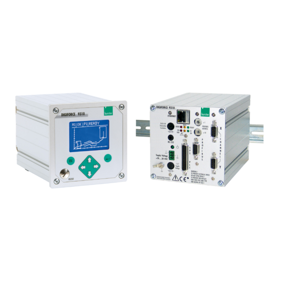
Installation Installation Connection of fieldbus lines burster devices with a PROFIBUS option have a 9-pin SUB-D female connector for the fieldbus connection 5 DGND (CNTR-N) NC* 9 4 NC* (CNTR-P) RxD/TxD-N RTS 8 3 RxD/TxD-P (P24) NC* 7 2 NC *(M24) - Page 9 Installation Commercially available connectors allow the incoming data cable to be connected directly to the outgoing data cable in the connector. This avoids stubs, and the bus connector can be connected to the bus or disconnected from the bus at any time without interrupting data traffic. These connectors include a bus termination that can be switched in or out.
-
Page 10: Configuring A Profibus Dp System
Installation Configuring a PROFIBUS DP system PROFIBUS configurator System configuration Device master data files GSD files PROFIBUS-DP DIGIFO Field DIGIFO Drive Field device module device ® Configuration menu in DIGIFORCE type 9310 [Enter] Display Initial display “MEASUREMENT” MINIMUM SETUP MENU CONFIGURATION GENERAL SETTINGS PROFIBUS... -
Page 11: Profibus
PROFIBUS DP overview PROFIBUS Overview PROFIBUS was developed as an open fieldbus. It was standardized in the German standard DIN 19 245 and was later incorporated in the European standard EN 50 170, Vol. 2. PROFIBUS is a medium for pure data transfer, like the RS232 standard for instance. - Page 12 PROFIBUS DP overview PROFIBUS DP data transfer The master always transfers the same number of data bytes with each of its slaves in turn (always around a loop), thereby always keeping the total transfer time constant. Each slave must respond within a fixed time slot. Theoretically, 240 bytes are possible in each response.
-
Page 13: General Information
PROFIBUS DP overview General information For PROFIBUS DP (cyclical data traffic), one must define at the configuration stage how many bytes are transferred between master and slave during each cyclical access. (GSD file) The device is controlled using the data transferred from master to slave. This ®... -
Page 14: Data Conversion
PROFIBUS DP overview Data conversion 4.4.1 Description of the data formats in this manual Data transfer for the various modes is described below. The terms PLC inputs ® and PLC outputs refer to the DIGIFORCE 9310 unit. These terms are reversed when referred to the master. -
Page 15: Profibus Dp Data Protocol
PROFIBUS DP data protocol PROFIBUS DP data protocol Transfer from master to slave ® 2 bytes of PLC-In data for the DIGIFORCE is always transferred from the ® PROFIBUS master to the DIGIFORCE . These bits have the same function ®... -
Page 16: Message Structure / Transfer From Slave To Master
PROFIBUS DP data protocol Message structure / Transfer from slave to master Mode Contents Length/bytes 3 bytes Min. general curve data Σ 27 bytes Full general curve data Σ 51 bytes W1E/E Σ 19 Byte Full general curve data W1E/E Σ... -
Page 17: Meaning Of The Contents Of The Different Protocol Modes
PROFIBUS DP data protocol Meaning of the contents of the different protocol modes PLC-Out: ® The data refers to the PLC output of the DIGIFORCE . The data described ® here is the data transferred from the DIGIFORCE type 9310 to the master. The function of the PLC-In / PLC-Out bits is identical to the parallel PLC I/O ports on the unit itself and can be found from the operating manual for the unit. -
Page 18: Message Structure / Data Break-Down
PROFIBUS DP data protocol Message structure / data break-down 5.4.1 Minimum general curve data: Min. Y of whole curve (X-coordinate) 4-byte float number (see appendix A) Min. Y of whole curve (Y-coordinate) 4-byte float number ( “ Max. Y of whole curve (X-coordinate) 4-byte float number ( “... -
Page 19: Byte Reference List
PROFIBUS DP byte reference list Byte reference list 5.5.1 Mode 1 (PLC-Out) Data from master to slave Byte Function Section Comments PLC inputs Byte 1 5.1.1 PLC inputs Byte 2 5.1.2 Data from slave to master Byte Function Section Comments PLC outputs Byte 1 5.3.1 PLC outputs Byte 2... -
Page 20: Mode 3 (Plc-Out, Full General Curve Data)
PROFIBUS DP byte reference list Byte Function Section Comments AbsMaxY; Y-coord. (1st byte) 5.4.1 min. general curve data: AbsMaxY; Y-coord. (2nd byte) 5.4.1 Max. Y of whole curve AbsMaxY; Y-coord. (3rd byte) 5.4.1 Y-coordinate AbsMaxY; Y-coord. (4th byte) 5.4.1 (32-bit float) Last Point;... - Page 21 PROFIBUS DP byte reference list Byte Function Section Comments AbsMinY; X-coord. (1st byte) Full general curve data: 5.4.2 AbsMinY; X-coord. (2nd byte) Min Y of whole curve 5.4.2 AbsMinY; X-coord. (3rd byte) X-coordinate 5.4.2 AbsMinY; X-coord. (4th byte) (32-bit float) 5.4.2 AbsMinY;...
-
Page 22: Mode 4 (Plc-Out, Window 1 E/E)
PROFIBUS DP byte reference list 5.5.4 Mode 4 (PLC-Out, Window 1 E/E) Data from master to slave Byte Function Section Comments PLC inputs (1st byte) 5.1.1 PLC inputs (2nd byte) 5.1.2 Data from slave to master Byte Function Section Comments PLC outputs Byte 1 5.3.1 PLC outputs Byte 2... -
Page 23: Mode 5 (Plc-Out, Full General Curve Data, Window 1 E/E)
PROFIBUS DP byte reference list 5.5.5 Mode 5 (PLC-Out, Full general curve data, Window 1 E/E) Data from master to slave Byte Function Section Comments PLC inputs (1st byte) 5.1.1 PLC inputs (2nd byte) 5.1.2 Data from slave to master Byte Function Section... - Page 24 PROFIBUS DP byte reference list Byte Function Section Comments First Point; X-coord. (1st byte) Full general curve data: 5.4.2 First Point; X-coord. (2nd byte) First curve value 5.4.2 First Point; X-coord. (3rd byte) X-coordinate 5.4.2 First Point; X-coord. (4th byte) (32-bit float) 5.4.2 First Point;...
-
Page 25: Mode 6 (Plc-Out, Windows 1-2 E/E)
PROFIBUS DP byte reference list 5.5.6 Mode 6 (PLC-Out, Windows 1-2 E/E) Data from master to slave Byte Function Section Comments PLC inputs (1st byte) 5.1.1 PLC inputs (2nd byte) 5.1.2 Data from slave to master Byte Function Section Comments PLC outputs Byte 1 5.3.1 PLC outputs Byte 2... -
Page 26: Mode 7 (Plc-Out, Full General Curve Data, Windows 1-2 E/E)
PROFIBUS DP byte reference list 5.5.7 Mode 7 (PLC-Out, Full general curve data, Windows 1-2 E/E) Data from master to slave Byte Function Section Comments PLC inputs (1st byte) 5.1.1 PLC inputs (2nd byte) 5.1.2 Data from slave to master Byte Function Section... - Page 27 PROFIBUS DP byte reference list Byte Function Section Comments First Point; X-coord. (1st byte) Full general curve data: 5.4.2 First Point; X-coord. (2nd byte) First curve value 5.4.2 First Point; X-coord. (3rd byte) X-coordinate 5.4.2 First Point; X-coord. (4th byte) (32-bit float) 5.4.2 First Point;...
-
Page 28: Mode 8 (Plc-Out, Windows 1-3 E/E)
PROFIBUS DP byte reference list Byte Function Section Comments Exit window 2; X-coord. (1st byte) Window 2 5.4.3 Exit window 2; X-coord. (2nd byte) Exit 5.4.3 Exit window 2; X-coord. (3rd byte) X-coordinate 5.4.3 Exit window 2; X-coord. (4th byte) (32-bit float) 5.4.3 Exit window 2;... - Page 29 PROFIBUS DP byte reference list Byte Function Section Comments 23 Entry window 2; Y-coord. (1st byte) Window 2 5.4.3 24 Entry window 2; Y-coord. (2nd byte) Entry 5.4.3 25 Entry window 2; Y-coord. (3rd byte) Y-coordinate 5.4.3 26 Entry window 2; Y-coord. (4th byte) (32-bit float) 5.4.3 Exit window 2;...
-
Page 30: Mode 9 (Plc-Out, Full General Curve Data, Windows 1-3 E/E)
PROFIBUS DP byte reference list 5.5.9 Mode 9 (PLC-Out, Full general curve data, Windows 1-3 E/E) Data from master to slave Byte Function Section Comments PLC inputs (1st byte) 5.1.1 PLC inputs (2nd byte) 5.1.2 Data from slave to master Byte Function Section... - Page 31 PROFIBUS DP byte reference list Byte Function Section Comments First Point; X-coord. (1st byte) Full general curve data: 5.4.2 First Point; X-coord. (2nd byte) First curve value 5.4.2 First Point; X-coord. (3rd byte) X-coordinate 5.4.2 First Point; X-coord. (4th byte) (32-bit float) 5.4.2 First Point;...
- Page 32 PROFIBUS DP byte reference list Byte Function Section Comments Exit window 2; X-coord. (1st byte) Window 2 5.4.3 Exit window 2; X-coord. (2nd byte) Exit 5.4.3 Exit window 2; X-coord. (3rd byte) X-coordinate 5.4.3 Exit window 2; X-coord. (4th byte) (32-bit float) 5.4.3 Exit window 2;...
-
Page 33: Glossary
Glossary Glossary Alarm model: Optional PROFIBUS service for acyclical data traffic. Not ® supported by the DIGIFORCE type 9310. ASIC: User-specific IC containing either part or all of the PROFIBUS protocol enabling PROFIBUS interfacing using just a few additional components. The SPC 42 (SIEMENS PROFIBUS ®... - Page 34 Glossary ISO: International Organization for Standardization LSPM2, SPM2: PROFIBUS ASICs for simple slave applications. Mandatory These are the services that every PROFIBUS station must services: support. Master class 1: A master that implements the transfer of the user data. Usually a PLC or a PC.
- Page 35 Glossary Process Automation. PROFIBUS definition process PROFIBUS PA: automation in accordance with IEC 1158-2 and DIN E 19245 Part 14. The protocol is very similar to PROFIBUS DP but has a different physical bus design. Typically used in the chemicals ®...
-
Page 36: Appendix A: Representation Of Floating-Point Values
Appendix Appendix A: Representation of floating-point values Floating-point numbers from measurement results are transferred as 4-byte float values as specified in IEEE-754-1985. The following examples explain how the 4 bytes are interpreted in order to obtain the floating-point values. What components make up a float number? A floating-point number represented as a 4-byte float value consists of three elements: the sign bit (sign), the exponent (ex) and the mantissa (mant). - Page 37 Appendix x = -0,25 is represented as -1.0 * 2 , i.e. sign bit (sign): 1 (negative) exponent (ex): 125 – 127 = -2 mantissa (mant): 0.0 + 1.0 = 1.0 giving: − − − − − − − Encoding of the three formula components in the four bytes 1st byte (first byte) Bit 7 Bit 6...
- Page 38 Appendix The following 4 bytes were received: (Byte 1) (Byte 2) (Byte 3) (Byte 4) (first byte received) (last byte received) 0x3F 0x40 0x00 0x00 0011 1111b 0100 0000b 0000 0000b 0000 0000b 011 1111 100 0000 0000 0000 0000 0000b E=0111 1110b M=100 0000 0000 0000 0000 0000b E=0x7E (dec.126)
- Page 39 Appendix Calculation tip This calculation can be performed relatively easily by bit manipulation directly at the binary level using the following sequence of operations: First, as described above, the three components of sign bit, exponent and mantissa must be obtained from the four bytes by copying and masking bits. Example: As described above, the bytes 0x3F,0x40,0x00,0x00 become...
-
Page 40: Appendix B: Byte Sequence Of Float Values
Appendix Appendix B: Byte sequence of float values In the DIGIFORCE 9310, one can reverse the order of the 4 bytes making up a float number as specified in IEEE-754 by breaking and resoldering solder bridges on the PROFIBUS board. Normally this is not necessary; however there are PROFIBUS masters whose conversion routine expects a different sequence. - Page 41 Appendix (1) Remove all connectors from the unit. Disconnect the unit from the power supply. (2) Use a TORX screwdriver (size 02) to undo the four screws on the rear of the unit. (3) Pull out the rear panel together with all four circuit boards from the unit. (4) Undo the two Phillips screws holding the PROFIBUS board in place.
Need help?
Do you have a question about the DIGIFORCE 9310 and is the answer not in the manual?
Questions and answers