Burster DIGIFORCE 9307 Operation Manual
Hide thumbs
Also See for DIGIFORCE 9307:
- Operation manual (503 pages) ,
- Operation manuals (175 pages) ,
- Operation manual (154 pages)
Table of Contents
Advertisement
Quick Links
Download this manual
See also:
Operating Manual
© 2016
burster präzisionsmesstechnik gmbh & co kg
All rights reserved
Valid from: 31.08.2016
OPERATION MANUAL
DIGIFORCE
Model 9307
Manufacturer
burster präzisionsmesstechnik gmbh & co kg
Talstraße 1 – 5
76593 Gernsbach
Tel.:
Fax.:
E-Mail:
®
Postfach 1432
76587 Gernsbach
(+49) 07224 / 6450
(+49) 07224 / 64588
info@burster.de
www.burster.de
2447-BA9307EN-5170-081524
Advertisement
Table of Contents

Related Manuals for Burster DIGIFORCE 9307


Summary of Contents for Burster DIGIFORCE 9307
- Page 1 OPERATION MANUAL ® DIGIFORCE Model 9307 © 2016 Manufacturer burster präzisionsmesstechnik gmbh & co kg burster präzisionsmesstechnik gmbh & co kg All rights reserved Talstraße 1 – 5 Postfach 1432 76593 Gernsbach 76587 Gernsbach Valid from: 31.08.2016 Tel.: (+49) 07224 / 6450 Fax.:...
- Page 2 (hereinafter referred to as "product") are the results of targeted development and meticulous research. As of the date of delivery, burster provides a warranty for the proper condition and functioning of these products covering material and production defects for the period specified in the warranty document accompanying the product.
-
Page 5: Table Of Contents
Table of contents Safety instructions ..................... 12 Symbols ......................12 Introduction ........................ 13 Intended use ......................13 Environmental conditions ..................13 2.2.1 Storage conditions .................. 13 2.2.2 Conditions of use ..................13 Personnel ......................13 Deliverables ......................14 Setting the user-interface language ..............14 Conversions and modifications ................ - Page 6 3.4.2 Trapezium window ................. 28 3.4.3 Thresholds ..................... 29 3.4.4 Envelopes ....................29 3.4.5 Mathematical functions ................30 3.4.6 Rotary switch evaluation ................. 31 Tare function ....................... 31 Sensor Test ......................32 Online switching points ..................32 Visualization, signaling and transfer..............33 Setup tools ......................
- Page 7 4.4.4.2 Connector D: Connection guidance for strain-gauge torque sensors that have integral angle measurement (e.g. 86043 or 86413) ..................47 4.4.5 Connector E: Resistance measurement ..........48 4.4.6 Connector F: Connection guidance for piezoelectric sensors ....49 4.4.7 RS-232 interface ..................50 4.4.8 USB-interface ..................
- Page 8 5.6.3 Strain gauge sensors ................69 5.6.4 Potentiometric sensors ................72 5.6.5 Sensors with standard signal ..............75 5.6.6 Piezoelectric sensors ................77 5.6.7 Sensors with incremental interface ............79 5.6.8 Connecting sensors that have an SSI interface ........82 5.6.8.1 SSI linear encoder ..............
- Page 9 5.8.4 Envelopes .................... 127 5.8.5 Mathematical functions ................. 128 5.8.6 Evaluations specific to rotary-switch testing .......... 131 5.8.6.1 Configuring rotary-switch evaluation ........132 5.8.6.2 Evaluation results for rotary switch evaluation: ...... 135 5.8.7 Tolerance band for evaluation elements ..........136 Online switching points ..................
- Page 10 6.1.3 Overall result of last measurement ............171 6.1.4 Individual evaluation status in measurement mode ......172 Measurement curve graphs (M1-1 to M1-3) ............174 6.2.1 Displaying numerical results in the M1-1 and M1-2 curve view ..... 175 6.2.2 Measurement curve graphs Y and Y (M1-3) ........
- Page 11 External actuation of sensor test ................ 202 Reference travel - incremental sensors ............. 202 Index .......................... 204 of 205...
-
Page 12: Safety Instructions
1 Safety instructions 1.1 Symbols On the device and in this manual the following symbols warn about risks: Symbols in this manual Notice A property damage can result if proper precautions are not taken Warning A property damage and a severe personal injury or death can result if proper precautions are not taken.. -
Page 13: Introduction
2 Introduction 2.1 Intended use ® The DIGIFORCE 9307 is an instrument for monitoring repetitive production processes. Its core function is to record and analyze signals from processes in which physical variables, such as force, pressure or torque, vary as a function of displacement, angle or time according to a defined curve. The resultant measurement curve is analyzed using graphical evaluation elements such as windows, envelopes and thresholds. -
Page 14: Deliverables
2.4 Deliverables ® • DIGIFORCE 9307 • Operating manual • 1 x mains cable • 2 x D-Sub male connector, 9-pin for sensor port (A, B) • 1 x D-Sub male connector, 37-pin for PLC port * • 1 x D-Sub female connector, 37-pin for PLC port * *) not included on instruments with Fieldbus option 2.5 Setting the user-interface language ®... -
Page 15: Installation In An Instrument Panel
2.7 Installation in an instrument panel Notice! Damage from excessive tightening torque Over tightening the screws can damage the fixing rails. • Use screws supplied to precut the thread. Minimum depth: must be able to insert screw as far as end face of fixing rail •... -
Page 16: Instrument Installation
2.7.2 Instrument installation Set of accessories 9300-Z003 Name Explanation ® DIGIFORCE 9307 Cut-out in the instrument panel Case feet Instrument panel Fixing rail (4x) Self-tapping Torx screw (4x) of 205... -
Page 17: Equipment Design And Functions
3 Equipment design and functions 3.1 Range of functions ® The DIGIFORCE 9307 monitors processes in which precisely defined functional relationships between two or more measured quantities need to be demonstrated. These measured quantities are recorded synchronously during the manufacturing process or subsequent functional testing to produce a measurement curve, which is then assessed using graphical and mathematical evaluation techniques. -
Page 18: Expansion Levels
3.1.1 Expansion levels ® The DIGIFORCE 9307 lets you store 32 or optionally 128 measurement programs, and to switch rapidly between them during the process. This means that you can simply change the measurement program when you change parts or when performing sequential sub-processes on one work piece. A measurement program contains the full set of parameters for the sensors, the measurement procedure and the evaluation of the measurement curve(s). -
Page 19: Suitable Sensors
3.2 Suitable sensors ® The DIGIFORCE 9307 is able to process signals from a vast range of sensor technologies. Note The physical connectors, and hence the sensors connected to these connectors, are assigned to the recorded curve variables (X/Y1/2 curve) in the "Channel settings" configuration menu. ®... -
Page 20: Recording Measurement Curves
Connection example: 3.3 Recording measurement curves An external control signal or an internal condition triggers the measurement. Immediately after ® receiving this active start condition, the DIGIFORCE 9307 starts to write to the data memory the ® values measured by the sensors as X/Y value pairs. The DIGIFORCE 9307 stops making these measurements when a stop condition is met. -
Page 21: Sampling Methods For The Measurement Signals
3.3.2 Sampling methods for the measurement signals ® The DIGIFORCE 9307 supports three different sampling methods, which you can also use in combination. In addition to time-based sampling, you can use a definable delta (Δ) X-value or delta (Δ) ® Y-value to record the pairs of curve values. -
Page 22: Absolute Reference
3.3.3.1 ABSOLUTE reference With the ABSOLUTE setting you are defining the X-axis reference of the measurement curve to be the zero point of the sensor connected to that channel. For sensors that provide relative measurements, such as incremental linear or rotary encoders, the origin of the X-axis can also be the start signal for the measurement. -
Page 23: Final Force Reference
3.3.3.2 FINAL FORCE reference ® With the FINAL FORCE reference, the DIGIFORCE 9307 delays the curve to after the measurement phase and references it to the last measurement point (final force). For a measurement curve with a ® forward and return section, the DIGIFORCE 9307 sets the turning point as the zero point when "final force"... -
Page 24: Reference Line Reference (Overshoot/Undershoot)
3.3.3.3 REFERENCE LINE reference (overshoot/undershoot) ® With the REFERENCE LINE reference, the DIGIFORCE 9307 delays the curve until after the measurement phase. It then references the curve to the point where the Y-value went above or below a configurable Y-level. If the final force of a pneumatic or hydraulic press varies, then using the final force as a reference would produce a spread in otherwise identical measurement curves. -
Page 25: Trigger Reference (Overshoot/Undershoot)
3.3.3.4 TRIGGER reference (overshoot/undershoot) Unlike the references ABSOLUTE, FINAL FORCE and REFERENCE LINE, with the TRIGGER reference, recording of measurements does not start until readings go above or below the configured ® threshold (e.g. force threshold). Then the DIGIFORCE 9307 writes the subsequent value pairs of the ®... -
Page 26: Evaluation Methods
3.4 Evaluation methods ® As a truly multi-purpose evaluation tool, the DIGIFORCE 9307 offers a wide selection of configurable evaluation elements. These can be used for OK/NOK classification of a vast range of curve types. In addition to traditional evaluation windows with defined entry and exit sides, you can also use thresholds, trapeziums of type X or Y and envelopes as graphical evaluation tools. -
Page 27: Evaluation Windows
3.4.1 Evaluation windows You can enable up to ten windows in one measurement program. You define the "Window evaluation element” by the corner points of a rectangle: X and Y . You can specify almost any criteria for how the measurement curve enters or exits the window. For instance, the block situation of a press-insertion process can be monitored using "Entry bottom"... -
Page 28: Trapezium Window
3.4.2 Trapezium window ® The DIGIFORCE 9307 classifies trapezium windows into two types: the X trapezium and the Y trapezium. The X trapezium uses fixed X limits, X and X ; the Y trapezium uses fixed Y limits, and Y You can enable up to four trapezium windows in one measurement program. -
Page 29: Thresholds
3.4.3 Thresholds The "Threshold" evaluation element can be used to calculate and monitor where the measurement curve passes through a defined X-value or Y-value. As user, you can choose between threshold type X or Y. You can enable up to four thresholds at once in one measurement program. Thresholds output an OK/NOK result after the measurement phase. -
Page 30: Mathematical Functions
3.4.5 Mathematical functions You can use the mathematical functions to perform up to ten basic operations (addition, subtraction, multiplication and division). These can be applied, for instance, to the results of the graphical ® evaluation elements. The DIGIFORCE 9307 can display the results of these functions as values in a measurement window. -
Page 31: Rotary Switch Evaluation
3.4.6 Rotary switch evaluation ® The DIGIFORCE 9307 can use the "Rotary switch evaluation" function to monitor periodic cycles between maxima and minima. These periodic variations arise, for instance, when measuring the torque and angle for rotary controls. To monitor such curves, in the rotary switch evaluation elements you can define up to two independent tolerance bands per measurement, each band containing up to 32 maxima and 32 minima respectively. -
Page 32: Sensor Test
3.6 Sensor Test Regular checking of sensors plays a crucial role in the test reliability of a quality control system. This is ® done by applying defined physical quantities to the sensors. The DIGIFORCE 9307 then evaluates the resultant electrical signals. To program the values for these checks, a feed unit, for example, moves into a reproducible position, ®... -
Page 33: Visualization, Signaling And Transfer
3.8 Visualization, signaling and transfer ® Immediately a measurement has finished the DIGIFORCE 9307 shifts into the evaluation phase. In this phase, it checks whether the measurement curve satisfies the conditions set by the evaluation elements such as windows and envelopes or by the mathematical functions. If this is the case, the ®... -
Page 34: Controls And Connections
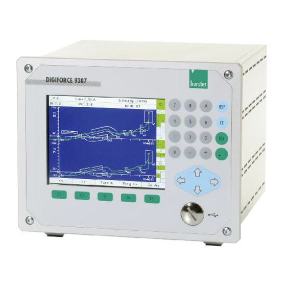
4 Controls and connections ® 4.1 DIGIFORCE 9307, front name meaning Screen Number keys [BSP], Backspace key [CE], Delete key [ESC], Escape key (back to measurement mode) ↵ , [Enter], Enter key Cursor ◄, ►, ▼, ▲ USB port (below screw) [F1] - [F5], Function buttons of 205... -
Page 35: Digiforce ® 9307, Rear
® 4.2 DIGIFORCE 9307, rear name meaning Power connection Power switch Profibus DP-V0 / DP-V1, optional Ethernet based fieldbus, optional C, Incremental connector EnDat, SSI E, Resistance measurement connector, optional D, Combined connector (incremental, strain gauge, potentiometer, Process signal), optional A, Standard analog connector (strain gauge, potentiometer, Process signal) Service connector (only for servicing) A, Standard analog connector (strain gauge, potentiometer, Process signal) -
Page 36: Grounding And Shielding
4.3 Grounding and shielding The DIGIFORCE 9307 is grounded via the PE conductor connected to the cooling unit (Class I appliance). All metal conducting parts are grounded in accordance with IEC60204 / EN60204. This grounding prevents dangerous voltages occurring on these parts in the event of unexpected and unnoticed insulation faults. - Page 37 Signal name Meaning IN_STEST Sensor Test IN_START External start / stop for measurement +24VDC_INT 24 V DC / 300 mA auxiliary power (linked to PLC outputs: pin 1) IN_STROBE Read measurement program no. on IN_PROG[ ] IN_PROG0 Measurement program no. bit 0 (binary coded) IN_PROG1 Measurement program no.
-
Page 38: Plc Output
4.4.1.2 PLC output ® The PLC outputs of the DIGIFORCE 9307 are positive switching (current sourcing logic). A total of eight outputs have a fixed assignment to the main functions such as OUT_OK, OUT_NOK, OUT_READY. You can assign the other 23 outputs to different functions, for instance to the single result from a selected evaluation element. -
Page 39: Plc Outputs With Fixed Assignment
PLC outputs 4.4.1.3 PLC outputs with fixed assignment Signal name Meaning +24VDC_INT 24 V DC / 300 mA auxiliary power (reference GND_EXT, pin 19, 37) OUT_READY Ready for the measurement OUT_OK Overall measurement result was OK OUT_NOK Overall measurement result was NOK OUT_NOK_ONL1 Online- NOK 1, online signal for "Window"... -
Page 40: Plc Outputs With Configurable Assignment
4.4.1.4 PLC outputs with configurable assignment PLC output Factory setting Output 1 OUT_STROBE; validity of echoed measurement program Output 2 OUT_OK_SENSORTEST; sensor test result Output 3 OUT_NOK_WINDOW_9 (Window 9 evaluation element NOK) Output 4 OUT_PROG0 (bit 0 of echoed measurement program) Output 5 OUT_PROG1 (bit 1 of echoed measurement program) Output 6... -
Page 41: Connectors A, B (Strain Gauge, Potentiometer And Normalized Signal)
4.4.2 Connectors A, B (strain gauge, potentiometer and normalized signal) Notice! Supply voltage +24 V DC! Connect only devices constructed for this supply voltage. Connector A and B Meaning + excitation for strain gauge, potentiometer + Sense +24 V DC / 300 mA transmitter excitation* - Sense - excitation for strain gauge, potentiometer + signal (input) -
Page 42: Connector A And B: Connection Guidance For Strain Gauge Sensors Without Sensor Lead
(female connector) Make the connections between the sense lines and excitation lines as close as possible to the sensor. We recommend using here the burster extension lead, model 99209-609A-xxxyyyy (e.g. 099209- 609A-0150030 for fixed cable runs, length 3 m) of 205... -
Page 43: Connector A And B: Connection Guidance For Potentiometric Sensors
4.4.2.3 Connector A and B: Connection guidance for potentiometric sensors You can connect strain gauge sensors without sensor leads to connector "A“ and “B” View towards rear of unit (female connector) 4.4.2.4 Connector A and B: Connection guidance for normalized-signal sensors You can connect strain gauge sensors without sensor leads to connector "A“... -
Page 44: Connector C: Incremental Sensors And Endat/Ssi
4.4.3 Connector C: incremental sensors and EnDat/SSI Notice! Supply voltage +/-5 V DC! Connect only devices constructed for this supply voltage. Connector C Meaning T+ / ENDAT / SSI T- / ENDAT / SSI Reference ground ENDAT / SSI, ENDAT-GND - transmitter excitation -5 V DC / 300 mA + transmitter excitation +5 V DC / 300 mA* A+ / TTL, Sine 1 Vss, Sine 11 µAss, RS-422... -
Page 45: Connector C: Connection Guidance For Incremental Sensor
4.4.3.1 Connector C: Connection guidance for incremental sensor You can connect incremental sensors to connector "C". View towards rear of unit (female connector) 4.4.3.2 Connector C: Connection guidance for EnDat / SSI You can connect EnDat / SSI to connector „C“. View towards rear of unit (female connector) of 205... -
Page 46: Connector D: Incremental Sensors, Strain Gauge, Potentiometer And Normalized-Signal Sensors
4.4.4 Connector D: incremental sensors, strain gauge, potentiometer and normalized-signal sensors Notice! Supply voltage +15 V DC and +5 V DC! Connect only devices constructed for this supply voltage. Connector D Meaning + excitation for strain gauge, potentiometer + Sense - Sense + transmitter excitation +15 V DC / 200 mA + transmitter excitation +5 V DC / 300 mA*... -
Page 47: Connector D: Connection Guidance For Torque Sensors That Have Analog Process Signal And Integral Angle Measurement (E.g. 8661)
You can connect EnDat / SSI to connector „D“. View towards rear of unit (female connector) We recommend using the burster connecting cable, model 99163-540A-0150030 (length 3 m) 4.4.4.2 Connector D: Connection guidance for strain-gauge torque sensors that have integral angle measurement (e.g. 86043 or 86413) -
Page 48: Connector E: Resistance Measurement
4.4.5 Connector E: Resistance measurement Connector E Meaning + I (current output) + I (current output) Not used - I (current output) - I (current output) + U (signal input) Not used Not used - U (signal input) Connector E: View towards rear of unit (female connector) Note In the 100 mΩ... -
Page 49: Connector F: Connection Guidance For Piezoelectric Sensors
4.4.6 Connector F: Connection guidance for piezoelectric sensors Electrostatic discharge. Don't touch! Electrostatic discharge can damage the piezoelectric channel (F). Avoid electrostatic discharge at connector F. You can connect piezoelectric sensors to connector F (standard BNC socket). Connector F, View towards rear of unit of 205... -
Page 50: Interface
9307-P100 PLUS-Version) via the RS-232 interface. You can specify the baud rate and data format in the "General settings“ menu. Use a 1:1 connecting cable (burster part number 9900-K333, length 1.8 m) to connect to a PC -COM port. The protocol specification for the serial RS-232 interface is given in the separate ®... -
Page 51: Usb-Interface
DigiControl PC software (part number 9307-P101 or 9307- P100 PLUS-Version) via USB port. Use a connecting cable with back-to-back male connectors (burster part number 9900-K349, length 1.5 m) to connect to a PC USB port. ®... -
Page 52: Profibus Interface
The protocol specification for the USB port is given in the separate "DIGIFORCE 9307 Profibus manual“. 4.4.11 Ethernet-based fieldbus interface (dual RJ45) The details of the available Ethernet-based fieldbus interfaces are contained in a separate document (can be obtained from info@burster.de or by phoning +49-(0)7224-6450). of 205... -
Page 53: Instrument Configuration
5 Instrument configuration ® If you wish to configure setup values for the DIGIFORCE 9307, you must switch from measurement mode, which is automatically active after Power-On, to Configuration mode using the [F5] function key Menu structure Pressing [ESC] repeatedly takes you back into measurement mode from any submenu. of 205... -
Page 54: Minimal Setup Menu
5.1 Minimal Setup menu You can make the following settings in this menu: • Select a measurement program • Edit a measurement program name • Reset statistics for all measurement programs • Reset statistics for the current measurement program You can access the "Minimal setup menu" from measurement mode by pressing the [F5] function key. If you press the [F5] key again from the Minimal setup menu, you access the "Main setup menu"... -
Page 55: Main Setup Menu
5.2 Main setup menu From the Main setup menu you can make all the universal basic settings and configure settings that are specific to a measurement program. If password protection is enabled, a status field showing current login details (User or Master) is displayed in the header (top right). -
Page 56: Basic Setup Menu
5.3 Basic setup menu The "Basic setup menu" contains all the universal settings i.e. settings that are not specific to a particular measurement program. To access the menu: In measurement mode, press the [F5] key twice. Press the [Enter] key to open the "Basic setup menu". 5.3.1 Function keys assignments You can customize the assignment of the function keys [F1] to [F4] for the measurement mode. -
Page 57: Password Protection And Access Authorization
5.3.2 Password protection and access authorization Factory-set Master Password: 2609 Factory-set User Password: 2201 ® DIGIFORCE 9307 has a facility for managing Master/User access levels. With password protection enabled, specific configuration levels can be locked for the User application. A Master performs the role of an administrator for the instrument and has full access permissions. -
Page 58: Controlling The Measurement Display Menus
5.3.3 Controlling the measurement display menus In measurement mode, you can switch between several menus for displaying process results. With ® the DIGIFORCE 9307, you can enable/disable a total of eight different display menus. You can also ® specify whether or not the DIGIFORCE 9307 displays the last 10 measurement curves as a curve array in the graphical view of the measurement curve. -
Page 59: Operating Language
None, even, odd Parity Off, On Block check* 0 (the DIGIFORCE 9307 uses only address 0) Address * The separate interface specification contains information about the block check 5.3.8.2 Standard data format for the RS-232 interface: • 8 data bits •... -
Page 60: Usb Interface Settings
9307 as a virtual COM port. The drivers required for this are installed with the DigiControl PC software. If you wish to use PC-based communication without the DigiControl software, you can request the interface drivers from service@burster.com. 921600 (fixed setting) -
Page 61: Assigning Plc Outputs
5.3.9 Assigning PLC outputs You can customize the signals assigned to certain PLC outputs. Factory setting PLC output Factory setting Output 1 OUT_STROBE Output 2 OUT_OK_SENSORTEST Output 3 OUT_NOK_WINDOW_9 Output 4 OUT_PROG0 Output 5 OUT_PROG1 Output 6 OUT_PROG2 Output 7 OUT_PROG3 Output 8 OUT_PROG4... - Page 62 You can assign one of the following signals to each of these outputs. signal Meaning "OUT_S3" Switching signal S3 "OUT_S4" Switching signal S4 "OUT_STROBE" Validity signal for echoed measurement-program number "OUT_PROG0" Bit 0 of echoed measurement-program number "OUT_PROG1" Bit 1 of echoed measurement-program number "OUT_PROG2"...
-
Page 63: Acknowledgement Function
signal Meaning "OUT_NOK_THRESHOLD_2" NOK threshold 2 "OUT_NOK_THRESHOLD_3" NOK threshold 3 "OUT_NOK_THRESHOLD_4" NOK threshold 4 "OUT_NOK_ENVELOPE_1" NOK envelope 1 "OUT_NOK_ENVELOPE_2" NOK envelope 2 "OUT_NOK_MATHE_1" NOK mathematical evaluation, operand 1 "OUT_NOK_MATHE_2" NOK mathematical evaluation, operand 2 "OUT_NOK_MATHE_3" NOK mathematical evaluation, operand 3 "OUT_NOK_MATHE_4"... - Page 64 The following PLC outputs can be used for the Acknowledgement function: Signal for the external "GOOD acknowledgement“ (OK OUT_ACK_OK measurements) If the acknowledgement prompt for OK parts is enabled, this signal flashes until acknowledged Signal for the external "BAD acknowledgement“ (NOK OUT_ACK_NOK measurements) If the acknowledgement prompt for NOK parts is enabled, this...
-
Page 65: Order Sheet
5.3.11 Order sheet In the order sheet you can save/retrieve a wide range of information relating to the measurement, for instance: • Name of worker • Shift number • Shift name • Number of OK parts • Number of NOK parts •... -
Page 66: Profibus Settings (Option)
Vxxx2 option. Enter here the Profibus address for the unit. Station address Valid address range: 1 … 126 PROFIBUS: DIGIFORCE 9307 responds solely to control signals Control via (inputs) on the Profibus interface PLC: DIGIFORCE 9307 responds solely to control signals (inputs) on the PLC I/O interface. -
Page 67: Channel Settings
5.6 Channel settings In the "Channel settings" menu you can assign the physical connections (terminals A to F) to the active measurement channels X, Y1 and Y2. You have full flexibility in these assignments, i.e. you can assign an active measurement channel to each terminal. You can also define a pure time axis instead of a terminal, letting you record and evaluate synchronously up to two signal/time curves (Y1=f(t) and Y2=f(t)). -
Page 68: Signal)
Parameters in the "Channel settings" menu (menu 22 Active measurement channel X, Y and Y Channel X, Y You cannot edit this parameter Assignment of a physical terminal to the measurement Terminal channel X, Y or Y A to F, t (time) (You can also specify a time axis here.) Terminals A to F;... -
Page 69: Inverting Measurement Signals
5.6.2 Inverting measurement signals You can invert a measurement signal simply by changing the sign of the scaling values LOWER and UPPER SCALE VALUE. 5.6.3 Strain gauge sensors You can connect strain gauge sensors to the connectors A, B and D (option): Parameters in the "Strain gauge sensor"... - Page 70 OFF, 5, 10, 25, 50, Filter setting for measurement channel Filter 100, 200, 400, (Default value = 50 Hz) 800 Hz Input of lower scale value for 2-point scaling Lower scale value (typical value = 0) Input of upper scale value for 2-point scaling Upper scale value (typical value = 100% of sensor measurement range)
- Page 71 In this menu (menu 23), configure the sensor-specific settings for the strain-gage sensor. Exit the "Channel settings" menu and confirm your settings with [Enter]. Tare settings for strain-gage sensors In menu 23, "Strain gage sensor" channel settings, you can use the [F5] key to make additional tare settings for this channel.
-
Page 72: Potentiometric Sensors
5.6.4 Potentiometric sensors Potentiometric sensors can be connected to the interfaces A, B and D (option) Parameters in the "Potentiometric sensor" menu (menu 24) Potentiometer excitation voltage 5 V, 10 V Excitation Enable/disable additional sensor DC supply Transmitter supply ON / OFF Terminal A,B: + 24 V DC Terminal D: + 15 V DC Dimensional units of measurement channel... - Page 73 In measurement mode, press the [F5] "Config" key twice and then open the "Channel settings" menu (menu 22). Select the "Potentiometer" sensor type for the relevant terminal. Go to the "More" menu option and select this option. In this menu (menu 24), configure the sensor-specific settings for the potentiometric sensor.
- Page 74 Exit the "Channel settings" menu and confirm your settings with [Enter]. Tare settings for potentiometric sensors In menu 24, "Potentiometric sensor" channel settings, you can use the [F5] key to make additional tare settings for this channel. Pressing the [F5] key again takes you back to the channel settings menu.
-
Page 75: Sensors With Standard Signal
5.6.5 Sensors with standard signal Sensors with standard signal can be connected to the interfaces A, B and D (option) Parameters in the "Standard signal sensor" menu (menu 25) Selection of input range: 5 V or 10 V Input range 5 V / 10 V Enable/disable additional sensor DC supply Transmitter supply... - Page 76 In measurement mode, press the [F5] "Config" key twice and then open the "Channel settings" menu (menu 22). Select "Standard signal" as the sensor type for the relevant terminal. Go to the "More" menu option and select this option. In this menu (menu 25), configure the sensor-specific settings for the standard- signal sensor.
-
Page 77: Piezoelectric Sensors
5.6.6 Piezoelectric sensors Piezoelectric sensors can only be connected to the optional terminal F. Note ® For this function, your DIGIFORCE 9307 must be fitted with the optional "Terminal F" Parameter in „Piezo Sensor“ menu (Menu 26) Selection of input range for the piezoelectric Input range 1, 2, 5, 10, 20, 40, 80, charge input e.g. - Page 78 In measurement mode, press the [F5] "Config" key twice and then open the "Channel settings" menu (menu 22). Select terminal "F" (piezoelectric). Go to the "More" menu option and select this option. In menu 26, configure the sensor-specific settings for the piezoelectric sensor. Exit the "Channel settings"...
-
Page 79: Sensors With Incremental Interface
5.6.7 Sensors with incremental interface You can connect incremental sensors to terminals "C" and "D" (option). Note Terminal "D" can only be connected to digital incremental sensors using TTL or RS-422 levels. Since both channels "C" and "D" (option) use the same hardware counter, you can only ever enable just one ®... - Page 80 Grating period <value input> Interpolation factor for the external interpolation unit or Interpolation <value input> interpolation unit integrated in the sensor Display value: = grating period / interpolation factor <display value> Signal period Display value: = signal period / 4 Resolution <display value>...
- Page 81 In this menu (menu 27), configure the sensor-specific settings for the incremental sensor. Exit the "Channel settings" menu and confirm your settings with [Enter]. Example: Settings for an 8738-DK8xxxx sensor Reference signal when sliding shaft extended by 1 mm Reference mark Std value at reference <0.0000>...
-
Page 82: Connecting Sensors That Have An Ssi Interface
5.6.8 Connecting sensors that have an SSI interface You can connect sensors that have an SSI interface to connector C. Pulse diagram clock sequence least significant bit of complete SSI data most significant bit of complete SSI data Process data The least significant bit of the displacement/angle information is received on the LSB of the SSI data (right-aligned format) -
Page 83: Ssi Linear Encoder
Parameters in the "Terminal C SSI" menu (menu 76) SSI linear encoder 5.6.8.1 Linear encoder Sensor type: linear encoder Sensor type Binary, Gray Binary or Gray coding of SSI data bits Code Right-aligned The least significant bit of the displacement Format data is assigned to the LSB of the SSI data. -
Page 84: Ssi Singleturn Encoder
Please note: In most cases, 2-point scaling for SSI linear encoders is performed with a 1:1 assignment (e.g. upper/lower scale value 0/10 mm and upper/lower calibration value 0/10 mm). Alternatively, 2-point scaling could be used to translate values up or down (typically for rotating applications). SSI singleturn encoder 5.6.8.2 Singleturn encoder... -
Page 85: Ssi Multiturn Encoder
Please note: With SSI rotary encoders, 2-point scaling lets you convert a rotational movement into a linear movement, for example. Example Ball screw with pitch of 10.08 mm. 0 mm Lower scale value 10.08 mm Upper scale value 0 degrees Lower calibration value 360 degrees Upper calibration value... - Page 86 <input value> Value of the lower calibration value for 2-point Lower calibration value scaling. Can be entered or trained (using [F1] teach-in function) (typical value: "0") The teach-in function only works if the sensor is connected and the correct channel parameters have been set.
- Page 87 Select for the relevant channel (the channel on the coordinate axis) the connector C and the sensor type SSI. Go to the "More" menu option under Setup and select this option. In this menu (menu 76) make the sensor-specific settings for the SSI sensor. Close the Channel setup menu and confirm the settings with [ENTER].
- Page 88 Example Settings for a GEFRAN MK4-S sensor with SSI interface. Linear encoder GEFRAN Typ MK4-S-F-0200-G-4 0.005 mm resolution Sensor type Gray Code Right-aligned Format no parity bit Parity 200 kHz Frequency for the SSI clock signal Clock frequency 0.005 Displacement resolution in mm Resolution Total number of bits Number of bits (length)
-
Page 89: Connecting Sensors That Have An Endat 2.2 Interface
5.6.9 Connecting sensors that have an EnDat 2.2 interface You can connect sensors that have an EnDat 2.2 interface to connector C. Please note: Data acquisition is performed solely via the EnDat communications channel and not from any other additional incremental encoder signals that may be present. Parameters in the "Terminal C EnDat"... - Page 90 <input value> Value of the lower calibration value for 2- Lower calibration value point scaling. Can be entered or trained (using [F1] teach-in function) (typical value: "0") The teach-in function only works if the sensor is connected and the correct channel parameters have been set.
-
Page 91: Endat Singleturn Encoder
EnDat singleturn encoder 5.6.9.2 Ready, Error When the "Terminal C EnDat" menu is Status opened, the instrument tries to communicate with the sensor. If an EnDat 2.2 sensor is detected successfully, the <Ready> status is displayed, otherwise <Error>. EnDat <XYZ> Displays the type read from the sensor (e.g. -
Page 92: Endat Multiturn Angle Sensor
Please note: With EnDat rotary encoders, 2-point scaling lets you convert a rotational movement into a linear movement, for example. Example Ball screw with pitch of 10.08 mm. Lower scale value 0 mm Upper scale value 10.08 mm Lower calibration value 0 degrees Upper calibration value 360 degrees... - Page 93 <input value> Value of the lower calibration value for 2-point Lower calibration value scaling. Can be entered or trained (using [F1] teach-in function) (typical value: "0") The teach-in function only works if the sensor is connected and the correct channel parameters have been set.
- Page 94 Select for the relevant channel (the channel on the coordinate axis) the connector C and the sensor type EnDat. Go to the "More" menu option under Setup and select this option. When the menu is opened, the instrument communicates with the EnDat sensor. It reads out and displays the relevant sensor data.
- Page 95 Example Settings for a Heidenhain AT 1218 sensor with EnDat interface. Ready Status EnDat AT 1218 Name <12345678> Serial number of connected sensor Serial number Linear encoder Sensor type 22 bits Number of bits 12 mm Measuring length 0.00002 mm Resolution 8 MHz Max.
-
Page 96: Resistance Measurement
5.6.10 Resistance measurement You can connect resistances to connector E (option) Note ® For this function, your DIGIFORCE 9307 must be fitted with the optional "Channel E. Parameters in the "Resistance" channel settings menu (menu 28) 100 mΩ, 1 kΩ, Selection of required resistance range Input range 100 kΩ... -
Page 97: Torque Sensors With Integral Angle Measurement
You can connect torque sensors with integral angle measurement, such as sensor model 8661, to the DIGIFORCE 9307 either to the standard terminals using an additional Y-cable (e.g. terminal A for the analog torque signal and terminal C for the incremental angle signal) or directly to the optional combined terminal D. -
Page 98: Measurement Mode
5.7 Measurement mode In the "Measurement mode" menu (menu 20) you specify the conditions for signal recording in the measurement phase. To do you this you essentially need to set signal-sampling parameters, configure the X-reference for the measurement curve, the curve segment (forward curve segment or complete measurement curve) and the start/stop condition for the measurement phase. -
Page 99: Measurement Curve Reference
5.7.2 Measurement curve reference ® The DIGIFORCE 9307 provides the following X-references for referencing the measurement curve. Further details are explained in section 3.3.3 “Specifying the X-axis reference” on page 21. • Absolute • Final force • Y1 or Y2 reference line overrun •... -
Page 100: Final Force" Reference
5.7.2.2 "Final force" reference See also section 3.3.3.2 “FINAL FORCE reference” on page 23. Parameters in the "Measurement mode", Reference "Final force" (menu 20) Final force The last measurement point of the measurement Reference curve as it this final measurement is the reference point (X = 0). -
Page 101: Curve Recording, Return Point
5.7.3 Curve recording, return point ® The DIGIFORCE 9307 divides a recorded measurement curve into two curve segments: the forward and return segments. ® Using the "Record curve to" parameter, you can specify whether the DIGIFORCE 9307 records and evaluates only the "forward" curve segment or the "complete curve" (forward and return segments). The "Return point"... -
Page 102: Start/Stop Mode
Record curve to: Return point Return point: X 5.7.4 Start/Stop mode ® The DIGIFORCE 9307 lets the user set independent start/stop parameters for recording a measurement curve. Apart from the standard method using an external control signal to start or stop a measurement, it is also possible to use sensor signals as the start/stop control. -
Page 103: Bend-Up Factor
You also need to define the Y channel stop threshold (Y or Y stop value). Timeout: The measurement is only stopped when the defined time has elapsed Number of readings: The measurement is stopped as soon as the defined number of measurement- value-pairs have been recorded. -
Page 104: Finding The Bend-Up Factor
Example A ball bearing is pressed into a bearing cup with maximum force until the limit of travel is reached. The system design can mean that the maximum insertion force varies by up to 25 %. 5.7.5.1 Finding the bend-up factor You can find the bend-up factor from the gradient of a measurement curve in Graphical test operation. - Page 105 Method 1: finding the bend-up factor from a real measurement curve In the limit-of-travel region of the curve, use the cursor tool to find the X/Y coordinates of two measurement points that are spaced apart from each other. Calculate the difference values ∆X and ∆Y.
-
Page 106: Configuring Evaluation
5.8 Configuring evaluation ® You have two ways of enabling and configuring evaluation elements on the DIGIFORCE 9307. In the "Evaluation" configuration menu you can enable the evaluation elements and configure them by entering numeric values. This menu does not provide immediate visualization of how the evaluation element will look in the X/Y graph. -
Page 107: Configuring An Evaluation Window
Exit ® The DIGIFORCE 9307 linearly interpolates the window exit coordinate from the last measurement point inside the window limits and the first measurement point outside the window limits. If the measurement curve ends inside the window area, the ® DIGIFORCE 9307 outputs the last measurement point. - Page 108 this data with the new configuration. In total you can activate up to 10 different windows at once. Enable the window function by placing the cursor on the "Window" option then using the ◄ and ► buttons to enable the window. Then specify the position and size of the window.
- Page 109 ® When online evaluation is active, the DIGIFORCE 9307 enables the assigned online signal immediately on detecting that the curve has exited the window incorrectly. Note The entry/exit sides defined above are changed by activating online evaluation. Where "Final force" or "Reference line" is used for the X-reference, the online evaluation is always based on the absolute X-value, i.e.
- Page 110 Menu parameters Window configuration (Menu 17) Selection of window 1 to 10 Window number 1 … 10 Enable / Disable ON / OFF Window Window-position coordinate Xmin Xmin <value input> Window-position coordinate Xmax <value input> Xmax Window-position coordinate Ymin Ymin <value input>...
-
Page 111: Advanced Window Results
Assignment of relevant online signal Online Signal Number 1 ... 2 1: OUT_NOK_ONL1 2: OUT_NOK_ONL2 High active Active level of PLC I/O signal Online Signal (OUT_NOK_ONL1/2) Low active YES: The curve must pass through the window Evaluate only first once correctly, then the evaluation algorithm is passage stopped (equivalent to evaluation method used in the DIGIFORCE 9306) - Page 112 To access this "Advanced window configuration" menu, press [F5] "Advanced" in the "Window configuration" menu. You can then enable the following functions: Bend Note For this option you need to specify the two parameters "Delta gradient for bend" and "Delta Y bend". If the measurement curve is very noisy or has been damped for a gradual change in gradient, it may not be possible to find any bend in the curve.
- Page 113 Local maximum Note For this option you need to specify the parameter "Delta Y local maximum". Select a value for this that is greater than any Y-fluctuations that may be present (for instance caused by vibrations, ® electromagnetic interference…). This is essential for the DIGIFORCE 9307 to find the local maximum correctly.
-
Page 114: Trapezoid Window
Area ® The DIGIFORCE 9307 measures the area between the measurement curve and the bottom window limit (Y limit). ® The DIGIFORCE 9307 only includes the curve region enclosed by the window limits X and X 5.8.2 Trapezoid window You can define a trapezoid window by first defining two fixed values. Whether you need to define X-values or Y-values depends on the type of trapezoid window (X or Y). - Page 115 Single evaluation ® The DIGIFORCE 9307 can also output the evaluation result from an individual trapezoid window to the I/O interface or Fieldbus interface. Entry ® The DIGIFORCE 9307 linearly interpolates the window entry coordinate from the last measurement point outside the window limits and the first measurement point inside the window limits If the measurement curve starts from inside the window area, the ®...
-
Page 116: Configuring A Trapezoid Window
5.8.2.1 Configuring a trapezoid window In measurement mode, pressing the [F5] key twice, opens the "Evaluation" configuration menu and then either the "Trapezoid window X" menu or the "Trapezoid window Y" menu. ® The DIGIFORCE 9307 then displays the "Trapezoid window configuration" menu. Select a particular trapezoid window by entering the number of the window concerned. - Page 117 ® Now define whether the DIGIFORCE 9307 is meant to include the trapezoid window in the evaluation. When Evaluation is set to OFF, this trapezoid window does not affect the overall ® result. The DIGIFORCE 9307 calculates only the entry and exit points. Specify the curve segment for which the trapezoid window is active.
- Page 118 Menu parameters in "Trapezoid window X configuration" menu (menu 13) Selection of X trapezoid window 1 to 2 Number 1 … 2 Enable / Disable ON / OFF Window Trapezoid-position coordinate Xmin Xmin <value input> Trapezoid-position coordinate Xmax <value input> Xmax Trapezoid-position coordinate Ymin left Ymin left...
- Page 119 Menu parameters in "Trapezoid window Y configuration" menu (menu 14) Selection of Y trapezoid window 1 to 2 1 … 2 Number Enable / Disable Window ON / OFF Trapezoid-position Ymin <value input> Ymin Trapezoid-position Ymax Ymax <value input> Trapezoid-position coordinate Ymin left <value input>...
-
Page 120: Thresholds
5.8.3 Thresholds ® The DIGIFORCE 9307 classifies thresholds into two types. Threshold type X is orientated vertically at a defined X position. You can, however, set a range for the Y-values (Y to Y It is the exact opposite for threshold type Y. In this case, it is anchored horizontally at a defined Y-position, whereas the X-values can vary within a set range (X to X With threshold type Y, in addition to the Pass point (intersection point), you can define advanced... -
Page 121: Configuring A Threshold
5.8.3.1 Configuring a threshold In measurement mode, pressing the [F5] key twice, opens the "Evaluation" configuration menu and then the "Threshold" menu. ® The DIGIFORCE 9307 then displays the "Threshold configuration" menu. First select a particular threshold by entering the number of the threshold concerned. - Page 122 Now specify the direction in which the measurement curve passes across the threshold. You have the following options here: the measurement curve can cross the threshold from either side or just from one side. You also have the option to specify that the measurement curve must not cross the threshold at all.
-
Page 123: Advanced Results For Threshold Of Type Y
Forward, Return, Defines which curve segment the threshold Curve segment Complete curve applies to. YES: The curve must cross the threshold once Evaluate only first correctly, then the evaluation algorithm is passage stopped. YES / NO NO: The measurement curve is only allowed to cross the threshold once correctly for the window to be assessed as OK. - Page 124 Bend Note For this option you need to specify the two parameters "Delta gradient for bend" and "Delta Y bend". If the measurement curve is very noisy or has been damped for a gradual change in gradient, it may not be possible to find any bend in the curve. For "Delta Y bend", select a value that is greater than any Y-fluctuations that may be present (for instance caused by vibrations, electromagnetic interference…).
- Page 125 Local maximum Note For this option you need to specify the parameter "Delta Y local maximum". Select a value for this that is greater than any Y-fluctuations that may be present (for instance caused ® 9307 to find the by vibrations, electromagnetic interference…). This is essential for the DIGIFORCE local maximum correctly.
- Page 126 Area ® The DIGIFORCE 9307 measures the area between the measurement curve and the X-axis within the span of the type-Y threshold. ® The DIGIFORCE 9307 takes into account only those curve points within the limits X and X A = |A | + |A of 205...
-
Page 127: Envelopes
5.8.4 Envelopes ® In the DIGIFORCE 9307 you can only generate an envelope in Graphical Test Operation (Simple Test Operation menu), and you need to have at least one measurement curve available from which to generate the envelope. If you have an existing envelope available, you can modify the position of the envelope and also set the tolerance (Delta). -
Page 128: Mathematical Functions
5.8.5 Mathematical functions You can enable up to 10 mathematical functions in one measurement program. The ® DIGIFORCE 9307 provides the basic arithmetic operators of addition, subtraction, multiplication and division for defining these functions. You can use the result of one function as the operand for a ®... - Page 129 Specifying constants In measurement mode, press the [F5] key twice, open the "Evaluation" configuration menu and then the "Mathematical function" menu. Press the [F4] button "Constant". You can now select one of the constants and enter the new value. of 205...
- Page 130 Configuring a mathematical function Prerequisite: You must already have specified the constants and/or evaluation elements you require. In measurement mode, press the [F5] key twice, open the "Evaluation" configuration menu and then the "Mathematical function" menu. Place the cursor over one of the functions and press [Enter]. ®...
-
Page 131: Evaluations Specific To Rotary-Switch Testing
5.8.6 Evaluations specific to rotary-switch testing The rotary-switch evaluation facility lets you monitor curves that are periodic in nature and alternate between minima and maxima. You can find further information in section 3.4.6 “Rotary switch evaluation” on page 31. of 205... -
Page 132: Configuring Rotary-Switch Evaluation
5.8.6.1 Configuring rotary-switch evaluation In measurement mode, press the [F5] key twice, open the "Evaluation" configuration menu and then the "Rotary switch" menu. Within a measurement program, you can define up to two tolerance bands at once for rotary-switch evaluation. Select one of the two possible tolerance bands by placing the cursor on "Rotary switch element number"... - Page 133 Specify the number of minima and number of maxima that are meant to lie within the range of the rotary switch element. To do this, place the cursor over the relevant menu option and enter the number. Define the limits of the tolerance band within which the minima are allowed to vary.
- Page 134 Menu parameters configuring rotary-switch evaluation menu (Menu 73) Selection of element 1 or 2 Rotary switch element 1 … 2 number Rotary switch element ON / OFF Defines the left-most X-position Xmin <value input> e.g. start of angle range Defines the right-most X-position Xmax <value input>...
-
Page 135: Evaluation Results For Rotary Switch Evaluation
5.8.6.2 Evaluation results for rotary switch evaluation: OK/NOK Single evaluation Number of minima found Number of minimums Number of maxima found Number of maximums Mean of Y-values for all identified minima Y average of minimums Mean of Y-values for all identified maxima Y average of maximums Difference between the smallest and largest Max. -
Page 136: Tolerance Band For Evaluation Elements
5.8.7 Tolerance band for evaluation elements You can use the tolerance band for graphical evaluation elements to configure an additional hysteresis band around the limit values, for instance the entry and exit side of a window. Within this hysteresis band, the measurement curve can cross the boundary line of the evaluation element to and fro any number of times without causing an NOK evaluation. - Page 137 In measurement mode, press the [F5] key twice Press [Enter] to open the menu "Evaluation" menu Press the [F5] key (Tol band). In this menu (menu 75) you specify the values for the tolerance band you require. Values are entered separately for tolerance band X, Y1 and Y2 (tolerance band Y2 does not appear if this channel is disabled).
-
Page 138: Online Switching Points
5.9 Online switching points Warning! This is NOT a substitute for safety devices or protective measures. Online switching signals S1 to S4 are are NOT a substitute for safety devices or protective measures. • Use additional safety devices and protective measures. Note The switching signals S1 to S4 do not meet the requirements of a safety switch. - Page 139 Menu parameters for "Setup real time switch points S1 ... S4" (menu 12) Input of limit threshold Value Limit threshold Units display Shows the units for the measurement channel Unit Selection of active measurement channel for Channel X, Y respective switching signals S1 … S4 High / Low Selection of active-high or active-low Active...
-
Page 140: Simple Test Operation
5.10 Simple test operation The "Simple test operation" menu is split into two sub-menus: "Numerical test operation" and "Graphical test operation". You can switch between these two sub-menus using the [F5] key. In the "Numerical Test Operation" menu you can retrieve the live actual values of the active measurement channels X, Y and Y and retrieve the status of the PLC control signals (inputs and... -
Page 141: Numerical Test Operation - Overview
Press the [F5] key twice in measurement mode. ® The DIGIFORCE 9307 switches to the "Main setup menu". Select here the option "Test operation simple" and confirm your selection with the [Enter] button. The "Simple Test operation" menu contains two pages: the "Numerical test operation"... -
Page 142: Numerical Test Operation - Live Sensor Values
Function keys in numerical test operation Function key Function [F1] Tare X or Std valueX For absolute value sensors such as strain gauges, potentiometers or standard-signal sensors, the Tare X function can be used to zero the live actual sensor value of channel X, or set it to a definable tare default value. The tare default value can be set in the channel settings menu. -
Page 143: Numerical Test Operation - Plc Signals
Profibus Fieldbus option: the corresponding signals are displayed and set/reset. Note that on activating the IN_AUTO control input, the "Numerical test operation" menu will close automatically and the DIGIFORCE 9307 switches to measurement mode. The cursor (light blue) is highlighting the first input IN_START (pin 2) and the live state is displayed (0 / LOW in this case) The cursor sits over the first PLC input IN_START when you first open the menu. -
Page 144: Numerical Test Operation - Shunt Calibration
5.10.4 Numerical Test Operation - Shunt Calibration If you have assigned a strain gauge sensor to a measurement channel, you can check the measurement chain using a shunt resistor. ® During this check, the DIGIFORCE 9307 connects a precision resistor (shunt calibration resistor) between the negative line of the signal input and the negative line of the reference supply voltage. -
Page 145: Graphical Test Operation - Overview
5.10.7 Graphical Test Operation - Overview In graphical test operation you can perform measurements in one or more measurement programs and use the recorded measurement curve(s) to define the graphical evaluation elements such as windows, thresholds, trapezoids and envelopes. The 10 most recent measurement results from each measurement program are saved. -
Page 146: Graphical Test Operation - Zoom
Function keys in Graphical test operation (menu 61) Del Curve All measurement curves saved in the active measurement [F1] program are deleted Start Start/Stop measurement [F2] The measurement is normally started and stopped automatically according to the trigger condition set; see Measurement Mode section. If, however, during the test operation phase you are not yet able to use control signals to trigger the measurement, you have the option to use [F2] to start and stop the measurement. -
Page 147: Graphical Test Operation - Configuring Windows
5.10.9 Graphical Test Operation - Configuring windows In graphical test operation you can enable the "Window" evaluation element and place it, move it and change its size directly in the measurement curve diagram. To set all the parameters in full you can switch directly into the parameterization menu, "Window configuration"... - Page 148 Now specify the position of the window. To do this, switch to the "<<>>" menu option. Once you have switched to this option, you can immediately define the position of the window using the arrow keys. Now specify the size of the window. To do this, switch to the "<>" menu option. Under this menu option you can specify the window size by setting the two corners top-left and bottom-right.
-
Page 149: Graphical Test Operation - Configuring Trapezoid Windows
5.10.10 Graphical Test Operation - Configuring trapezoid windows In graphical test operation you can enable the "Trapezoid X" or "Trapezoid Y" evaluation element and place it, move it and change its size directly in the measurement curve diagram. To set all the parameters in full you can switch directly into the relevant parameterization menu, "Trapezoid window X configuration"... - Page 150 use the "Auto" zoom function. Further details about the zoom function are given in section 5.10.8 “Graphical Test Operation - Zoom” on page 146. Now specify the position of the trapezoid window. To do this, switch to the "<<>>" menu option. Once you have switched to this option, you can immediately define the position of the window using the arrow keys.
-
Page 151: Graphical Test Operation - Configuring Thresholds
5.10.11 Graphical Test Operation - Configuring thresholds In graphical test operation you can enable the Threshold evaluation element and place it, move it and change its size directly in the measurement curve diagram. To set all the parameters in full you can switch directly into the parameterization menu, "Threshold configuration"... - Page 152 Define the orientation of the threshold (type X or type Y). To do this, select the "Numerical" menu and assign the orientation type. The [ESC] key takes you straight back into graphical test operation. Now specify the position of the threshold. To do this, switch to the "<<>>" menu option.
-
Page 153: Graphical Test Operation - Configuring Envelopes
5.10.12 Graphical Test Operation - Configuring envelopes In graphical test operation you can generate the Envelope evaluation element. To do this, you first need to run at least one measurement. When generating the envelope, all the measurements available in the curve memory (10 measurement curves maximum) are used as the basis for calculating the envelope. - Page 154 In the next pop-up window, specify whether you want the envelope to be generated in the forward or return curve segment and press [Enter]. If the DIGIFORCE 9307 was able to generate the envelope correctly, the message "Envelope has been generated successfully" is displayed. Press [Enter].
- Page 155 Select the "Delta" option and define the additional tolerance band using the cursor keys. You can use [F1] and [F2] to switch between Delta max and Delta min. That completes the envelope generation process. In the "Numerical" submenu you can make numerical adjustments to the values you have set graphically such as the start and end positions.
-
Page 156: Graphical Test Operation - Cursor
5.10.13 Graphical test operation - Cursor You can use the cursor in graphical test operation to select each individual measurement pair and read off the associated X/Y values. Measurements for the selected value pair Function keys in graphical test operation Function key Function [F1]... -
Page 157: Graphical Test Operation - Reference Curve
5.10.14 Graphical test operation - Reference curve For each of the measurement curves Y1 and Y2 you can save a live measurement curve as the reference curve and display this curve in the graph in measurement mode. The reference curve is shown as a violet curve and can be used by an operator to identify any differences between the actual curve and ideal curve. - Page 158 Selecting individual curves from the curve array Prerequisite: The curve array display must be enabled. Go to the "Simple test operation" menu; if the "Graphical test operation" page is not displayed already, open it by pressing the [F5] key "Graph". Select the "Curve array"...
-
Page 159: Graphical Test Operation - Marks
5.10.16 Graphical test operation - Marks You can use the Marks function in Graphical test operation to display the individual measurement value pairs of a measurement curve. of 205... -
Page 160: Complex Test Operation
DIGIFORCE 9307, then once measurements of up to ten components are completed, the evaluation elements can be configured in each of the measurement programs on the basis of the recorded curves. -
Page 161: Sensor Test
Function key assignments in Complex test operation (Menu 67) Reset all All measurement curves in all measurement [F1] programs are deleted Reset prog All measurement curves in the active [F2] measurement program are deleted ---- No function [F3] Set prog The program selected by the cursor is selected [F4] as the active measurement program. - Page 162 Press the [F5] key twice in measurement mode to open the "Sensor test" menu. Enable the sensor test for the relevant measurement channel by setting it to "ON" Measure and save the live reading as reference value using the [F1] function key. Define the permitted tolerance for the OK/NOK decision Running the sensor test You can launch the sensor test manually in Numerical test operation by pressing the [F4] function key,...
-
Page 163: User Defined Values
5.13 User defined values ® The DIGIFORCE 9307 can display various measurement values in measurement mode, which you can also output via an interface. These measurement values include sensor live values, entry and exit values for windows, extreme values or the result of a mathematical function. Before the ®... - Page 164 Window Entry X Local maximum Y Entry Y Bend X Exit X Bend Y Exit Y Mean value Y Abs. minimum X Gradient Abs. minimum Y Area Abs. maximum X Coordinate Xmin Abs. maximum Y Coordinate Xmax Local minimum X Coordinate Ymin Local minimum Y Coordinate Ymax...
- Page 165 Envelopes Entry X Exit Y Entry Y Start X Exit X End X Activating values ® Prerequisite: The DIGIFORCE 9307 can only display the activated values if you have enabled them in the Evaluation menu. Press the [F5] "Config" function key twice in measurement mode. You are now in the "Main setup menu".
-
Page 166: Copying / Deleting A Measurement Program
5.14 Copying / Deleting a measurement program 5.14.1 Copying a measurement program or sensor settings If you want to re-use most of the settings in a measurement program, you can make a copy of the measurement program. You can then tweak these copies to suit the new requirements. If you want to use just the sensor settings of a particular measurement program in other measurement ®... -
Page 167: Deleting A Measurement Program
Under "Target program number from" or "Target program number to", enter a range for the program numbers for the copies. If you only want to make one copy, enter the same number for "Target program number from" and for "Target program number to". Now select "Copy whole setup". - Page 168 Under "Target program number from" or "Target program number to", enter the measurement programs that you want to delete. If you only want to delete one measurement program, enter the same number for "Target program number from" and for "Target program number to". Then select "Initialize target program(s)".
-
Page 169: Measurement Results Display
6 Measurement results display Note In the "Basic setup menu", you can change the function-key assignments and the display preferences for the individual measurement menus. The information in this manual, however, relates to the factory settings of the instrument. ® The DIGIFORCE 9307 starts automatically in "Measurement Mode"... -
Page 170: Global Header
Waiting for acknowledgement in acknowledgement mode (background S:Acknowledge color magenta) Edit mode has been opened using the relevant function key in S:Edit Mode active measurement mode. The DIGIFORCE 9307 can now switch to configuration mode despite active measurement-data logging by the of 205... -
Page 171: Overall Result Of Last Measurement
DigiControl software If the DIGIFORCE 9307 is integrated in the PC-based measurement data logging of the DigiControl software (DigiControl Measurement mode function), the status is shown in blue lettering. In this state, the DIGIFORCE 9307 cannot be switched directly into configuration mode using the [F5] function key. -
Page 172: Individual Evaluation Status In Measurement Mode
6.1.4 Individual evaluation status in measurement mode ® On the right-hand side of the screen, the DIGIFORCE 9307 indicates the individual results of the ® active evaluation elements. The DIGIFORCE 9307 identifies these results with their corresponding number. If an evaluation element is defined on the Y2 measurement curve but this curve is disabled (OFF) in the channel settings, the individual status is indicated in yellow. - Page 173 Table of user selected values (if configured) Statistical analysis Order sheet Results of rotary-switch evaluation In the Basic setup menu, you can disable those information pages that you do not need in measurement mode, so that you only scroll through the relevant pages with the [F1] and [F2] function keys.
-
Page 174: Measurement Curve Graphs (M1-1 To M1-3)
6.2 Measurement curve graphs (M1-1 to M1-3) The measurement curve plotted on an X/Y graph is displayed on the "measurement curve graphs" info pages (M1-1 to M1-3). If you have also defined an Y2-channel in the Channel settings, the ® DIGIFORCE 9307 not only displays the default measurement curve Y (X) but also shows the Y... -
Page 175: Displaying Numerical Results In The M1-1 And M1-2 Curve View
6.2.1 Displaying numerical results in the M1-1 and M1-2 curve view On the M1-1 or M1-2 info page containing the measurement curve graph, you have the option to display additional numerical results or sensor live values. The curve is then shown in the top half of the display, while up to six numerical values can be displayed in the lower half. -
Page 176: Measurement Curve Graphs Y And Y (M1-3)
6.2.2 Measurement curve graphs Y and Y (M1-3) ® When you enable the Y measurement channel in the Channel settings, the DIGIFORCE 9307 immediately configures the M1-3 info page automatically. This page displays the two-curve graph containing both measurement curves. Measurement curveY1 (X) Measurement... -
Page 177: General Curve Data (M2-1 And M2-2)
6.3 General curve data (M2-1 and M2-2) The General curve data info page displays coordinate pairs (X/Y value pairs) from the set of results "General curve data" for Y (X) or Y (X). The M2-2 page for Y (X) is only displayed if measurement channel Y has been enabled in the Channel settings. -
Page 178: Info Page Overall Result (M3)
6.4 Info page overall result (M3) The M3 info page lets you display the evaluation result as a global Good/Bad result (OK/NOK evaluation). You can opt to display the result as the text Pass/Fail or as a happy/sad smiley face. You can also add an acknowledgement function to the overall result page, which prompts for confirmation by the operator (see Configuration >... -
Page 179: Info Page, Entry/Exit For Windows (M4-1)
6.5 Info page, Entry/Exit for windows (M4-1) The M4-1 info page displays the Entry/Exit coordinate pairs for the active evaluation elements of type window (W). If evaluation windows are also enabled for the Y2(X) measurement curve, the information is displayed in a top section for the Y1(X) curve and in a bottom section for the Y2(X) curve. of 205... -
Page 180: Info Page, Entry/Exit (M4-2)
6.6 Info page, Entry/Exit (M4-2) The M4-2 info page displays the Entry/Exit coordinate pairs for the active evaluation elements of type threshold (TH), trapezoid window (TX or TY) and envelope (EN). If evaluation elements are also enabled for the Y2(X) measurement curve, the information is displayed in a top section for the Y1(X) curve and in a bottom section for the Y2(X) curve. -
Page 181: Info Page, User Selected Values (M5-1 And M5-2)
6.7 Info page, User selected values (M5-1 and M5-2) You can specify up to 24 measurement values or results for display in the User selected values tables M5-1 and M5-2. These values are selected in the Configuration under "Setup user-defined values" (Configuration >... -
Page 182: Info Page, Statistics (M6)
6.8 Info page, Statistics (M6) The Statistics info page shows the total percentage of failed parts (NOK evaluations) out of the total number of parts. It also shows the NOK percentage of all active individual evaluation elements with respect to the total number of NOK results. This display can help you quickly deduce the cause of any NOK measurements. - Page 183 The trapezoid X entry and exit values are displayed and analyzed. The frequency distribution between Y and Y is displayed and Trapezoid X analyzed. If an entry side or exit side is not configured, the respective diagram and analysis is not shown. The trapezoid Y entry and exit values are displayed and analyzed.
-
Page 184: Statistics, Histogram Info Page (M6-H)
6.8.1 Statistics, Histogram info page (M6-H) You can use the [F4] function key to switch between the Trend and Histogram views. The Histogram view shows the frequency distribution of the measured values (see table above) in eight fixed classes within the min/max limits. If the measured value cannot be found for a measurement, e.g. because the measurement curve does not even reach the window area, the frequency value of the ninth class (invalid value) is incremented. -
Page 185: Statistics, Trend Info Page (M6-T)
6.8.2 Statistics, Trend info page (M6-T) You can use the [F4] function key to switch between the Trend and Histogram views. The Trend view displays the relevant measurement value over the last 100 measurements maximum within the min/max limits. A red line is displayed if a measurement does not result in a measurement value. Selected evaluation element Min: minimum value in tolerance band... -
Page 186: Info Page, Order Sheet (M7)
6.9 Info page, Order sheet (M7) The Order sheet info page is not used for displaying specific measurement data or results. It is a "data container" via which you can transfer administrative or component-specific information for data logging purposes. You can edit the order sheet manually via the Basic setup menu (Configuration > Basic setup menu >... -
Page 187: Signal Timing Diagrams
7 Signal timing diagrams 7.1 Selecting a measurement program 7.1.1 Changing the measurement program without program acknowledgement * IN_PROG [6..0] for 128 measurement programs. Cycle a. The controller writes the required program number (coded in binary) to the ® address inputs and checks whether the DIGIFORCE 9307 is ready (OUT_READY =1). -
Page 188: Changing The Measurement Program With Program Acknowledgement
7.1.2 Changing the measurement program with program acknowledgement * IN_PROG[6..0] and OUT_PROG[6...0] for 128 measurement programs. You can define a user- configurable PLC output for the signal "OUT_PROG[6..0]“. Cycle a. The controller writes the required program number (coded in binary) to the ®... -
Page 189: Starting / Stopping A Measurement Externally
7.2 Starting / stopping a measurement externally You also have the option of using internal events to start a measurement in the DIGIFORCE 9307 and stopping them independently. You can configure the settings for this in the Measurement mode configuration menu (see section 5.7.4 ”Start/Stop mode on page 102). The signal timing diagrams for the measurement and evaluation phases follow exactly the same cycle as shown here. -
Page 190: With Measurement Data Logging
"OUT_OK“ and "OUT_NOK“ to 1 and "OUT_READY“ to 0. e. The PLC stops the measurement by setting the signal "IN_START“ to 0 The DIGIFORCE 9307 updates the result during the evaluation phase: g. OUT_OK = 1 and OUT_NOK = 0: OK measurement h. -
Page 191: External Tare
7.3 External tare 7.3.1 Without tare warning Standard cycle without monitoring of tare warning limit; measuring channel "Y1“ used as example Cycle ® a. The checks whether the DIGIFORCE 9307 is ready (OUT_READY =1). b. The PLC starts the tare process with "IN_TAREY1 = 1". ®... - Page 192 Cycle ® a. The checks whether the DIGIFORCE 9307 is ready (OUT_READY =1). b. The PLC starts the tare process with "IN_TAREY1 = 1". ® c. The DIGIFORCE 9307 then sets “OUT_READY" to 0. ® d. If the online sensor signal exceeds the set warning limit, the DIGIFORCE 9307 sets the output OUT_WARNING_TARE.
-
Page 193: Online Signals
7.4 Online signals 7.4.1 Window evaluation with online signal ® For the "Window“ evaluation element, you can specify that the DIGIFORCE 9307 enables the online signal "OUT_NOK_ONL1“ or "OUT_NOK_ONL2“ if a window evaluation criterion is infringed. This function is often used to monitor the initial-contact region of press-fit curves. If the curve exits the window incorrectly, for instance because misalignment of the parts to be joined ®... -
Page 194: Online Switching Signals S1 To S4
7.4.2 Online switching signals S1 to S4 ® The DIGIFORCE 9307 can enable the switching signals S1 to S4 in measurement mode and in setup mode if a measurement exceeds a set value. Warning! This is NOT a substitute for safety devices or protective measures. Online switching signals S1 to S4 are NOT a substitute for safety devices or protective measures. - Page 195 7.4.2.1 Switching signals for channel "X" with ABSOLUTE reference ® The DIGIFORCE 9307 sets a channel-X switching signal if the X-channel goes beyond the set X- channel value referred to the "Absolute“ reference. When the channel goes below the set value, the ®...
-
Page 196: Switching Signals For Channel "X" With Trigger Reference
7.4.2.2 Switching signals for channel "X" with TRIGGER reference ® The DIGIFORCE 9307 can only set/reset the switching signal for channel "X“ with trigger reference during an active measurement, i.e. after the trigger event. The reference used for channel "X" is the trigger event, for instance this may be the contact force of a press ram on a component. -
Page 197: Switching Signals For Channel "Y
7.4.2.3 Switching signals for channel "Y" ® The DIGIFORCE 9307 sets a channel-Y switching signal when the Y-channel exceeds the specified ® Y-channel value. When the channel goes below the set value, the DIGIFORCE 9307 resets the signal back to its original level. The signal can be set/reset in measurement mode when in standby (waiting to start measurement) and during an active measurement. -
Page 198: Acknowledgement Function
7.5 Acknowledgement function You can use the signal-light function with the DIGIFORCE 9307 to control indicator lights and a buzzer ® for direct visual and acoustic signaling of the OK/NOK evaluation. In addition, the DIGIFORCE 9307 can handle an acknowledge input for OK and/or NOK components where this is required. This acknowledge function is combined with the lock output "OUT_ACK_LOCK“. -
Page 199: Example Of A Nok Evaluation (Without Acknowledgement)
7.5.2 Example of a NOK evaluation (without acknowledgement) Configuration Acknowledgement function Acknowledge OK parts Acknowledge NOK parts * You can define a user-configurable PLC output for the signals "OUT_ACK_NOK“ and "OUT_ACK_LOCK“. of 205... -
Page 200: Example Of An Ok Evaluation (Without Acknowledgement)
7.5.3 Example of an OK evaluation (without acknowledgement) Configuration Acknowledgement function Acknowledge OK parts Acknowledge NOK parts * You can define a user-configurable PLC output for the signals "OUT_ACK_NOK“ and "OUT_ACK_LOCK“. of 205... -
Page 201: External Actuation Of A Statistics Reset
7.6 External actuation of a statistics reset You can use the "IN_RESET“ control signal to reset the piece counter and NOK counter and to reset ® the statistics from the evaluation elements. The DIGIFORCE 9307 resets the statistics from all the measurement programs in this case. -
Page 202: External Actuation Of Sensor Test
7.7 External actuation of sensor test ® You can use the "IN_STEST“ signal to run the sensor test configured in the DIGIFORCE 9307. You can configure the sensor test to check the sensor signals from the measurement channels X, Y against a saved value, including a definable tolerance. - Page 203 Successful reference travel Invalid reference travel * You can define a user-configurable PLC output for the signal “OUT_REF_MEAS_OK”. In this example of a reference travel cycle, the sensor has reached only one reference mark. For a valid i.e. successful reference travel cycle, however, the sensor would need to have reached at least two reference marks.
-
Page 204: Index
8 Index Absolute maximum ........95, 107 Function keys ............ 53 Absolute minimum ........95, 107 Acknowledgement function ....... 60 Advanced configuration of evaluation windows 94 Advanced results for threshold of type Y ..106 General curve data .......... 145 Area ............97, 108 Global header .......... - Page 205 Overall result ..........153 Software version ..........55 Status display ..........152 Strain gage sensors........... 66 Strain gauge sensors, connection ..... 39 Pass ............... 103 Strain gauge sensors, connection with senor lead39 Pass/Fail ............60, 160 Password protection ......... 54 Personnel ............12 Piezoelectric .............
Need help?
Do you have a question about the DIGIFORCE 9307 and is the answer not in the manual?
Questions and answers