Table of Contents
Advertisement
Quick Links
©2009
burster
präzisionsmesstechnik gmbh & co kg
All rights reserved
Valid from:
2009-02-27
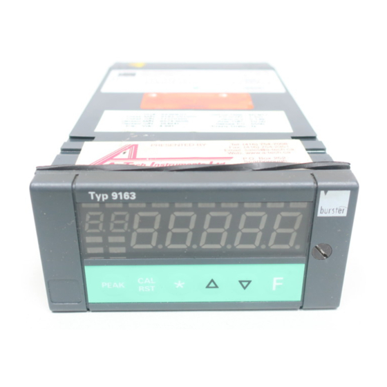
Digital indicator
Model 9163
Manufacturer:
burster praezisionsmesstechnik gmbh & co kg
Talstrasse 1 – 5
76593 Gernsbach,
Germany
Tel.:
(+49) 07224 / 6450
Fax.:
(+49) 07224 / 64588
E-Mail:
info@burster.de
www.burster.de
P.O. Box 1432
76587 Gernsbach,
Germany
376-009163EN-5170-021511
Advertisement
Table of Contents

Related Manuals for Burster 9163


Summary of Contents for Burster 9163
- Page 1 Digital indicator Model 9163 ©2009 burster Manufacturer: präzisionsmesstechnik gmbh & co kg burster praezisionsmesstechnik gmbh & co kg All rights reserved Talstrasse 1 – 5 P.O. Box 1432 76593 Gernsbach, 76587 Gernsbach, Germany Germany Valid from: 2009-02-27 Tel.: (+49) 07224 / 6450 Fax.:...
- Page 2 Furthermore, burster assumes no liability for direct, indirect or incidental damages as well as consequential or other damages arising from the provision and use of the present documentation.
- Page 3 E G - K o n f o r m i t ä t s e r k l ä r u n g EC- Declaration of Conformity according to EN ISO/IEC 17050-1:2004 Name des Herstellers: burster präzisionsmesstechnik gmbh & co kg Manufacturer’s Name: Talstr. 1-5 Adresse des Herstellers: Manufacturer’s Address:...
- Page 4 Model 9163 Digital indicator Page 4...
- Page 5 Digital indicator Model 9163 9163 as panel-mount unit 9163 as bench-top unit Page 5...
- Page 6 Model 9163 Digital indicator Page 6...
- Page 7 Digital indicator Model 9163 Warning! The following instructions must be followed to prevent electric shock and injuries: Observe all safety notices and instructions. Do not connect voltages that are higher than those specified. The voltage ranges supported are listed in the technical specifications.
- Page 8 Model 9163 Digital indicator Page 8...
-
Page 9: Table Of Contents
Installation instructions................18 Electrical connections ..................... 21 Panel-mount unit ....................22 3.1.1 Inputs and outputs on the 9163 Vxxxx0 version (single-channel unit) ..22 3.1.2 Inputs and outputs on the 9163 Vxxxx1 version (two-channel unit) ..27 3.1.3 Inputs and outputs on both versions ............35 3.1.4... - Page 10 Model 9163 Digital indicator Basic operation .........................59 Accessing a specific menu ..................59 Accessing the parameters in the menu ..............59 Adjusting a parameter value..................60 Returning to the main menu ..................60 Operating hierarchy....................61 6.5.1 Level 1 .....................61 6.5.2 Main menu ....................62 Retrieving information on the current status ..............63 Displaying the software version................63...
- Page 11 Digital indicator Model 9163 10.3.1 Mathematical functions ................. 105 10.3.2 Enabling the alarm limits ............... 112 10.3.3 Button assignment ................112 10.3.4 Digital inputs ..................115 10.3.5 Display settings..................117 10.4 Input linearization ....................120 10.5 Sensor-specific calibration.................. 124 10.5.1 Potentiometer or linear signals.............. 124 10.5.2 Strain gage sensors ................
- Page 12 Model 9163 Digital indicator Page 12...
-
Page 13: Introduction
The 9163 digital indicator is designed to measure rapidly changing electrical quantities. It can be used in numerous potential applications including differential measurements. The inputs of the 9163 are configured via the keypad. They are suitable for standard linear signals and for pressure transducers, load cells, potentiometers, thermocouples and resistance thermometers. Custom linearization of the inputs is also possible. -
Page 14: Customer Service
The serial number is shown on the type plate. 1.2.2 Factory warranty burster praezisionsmesstechnik gmbh & co kg provides a manufacturer's warranty for a period of 24 months after delivery. Any repairs required during this time will be made without charge. -
Page 15: Equipment Data
Model 9163 1.2.4 Equipment data Please enter the information from the type plate in the table below after unpacking the instrument. If you need to contact the burster Customer Service department, you will need to quote this information. (serial number) CODE:... -
Page 16: Digivision 9163-P100 Software
Digital indicator 1.4.3 DigiVision 9163-P100 software The 9163 digital indicator is part of an equipment family supported by the PC-based DigiVision data acquisition software. The digital indicator must have the RS232 / RS485 option to be able to use this software tool. -
Page 17: Preparing For Use
Required options and accessories present o Correct supply voltage Please notify burster immediately of any discrepancies, missing parts or signs of damage. Before installing the 9163 series unit in the instrument panel, read section 2.2: "Installation / panel- mounting". Page 17... -
Page 18: Installation / Panel-Mounting
2.2 Installation / panel-mounting 2.2.1 Installation dimensions 44,5 Figure 1: Installation dimensions of the 9163 digital indicator (dimensions in millimeter) 2.2.2 Installation instructions Read the basic installation rules before you install the unit. If you do not follow our safety instructions, there may be problems with electrical safety and electromagnetic compatibility. - Page 19 Digital indicator Model 9163 If sensors are operating in an inflammable or explosive atmosphere: Connect these sensors to the unit solely via suitable isolating points. All interfaces must comply with the applicable regulations. Lay the mains-voltage cables separately from the input and output lines to the unit.
- Page 20 Model 9163 Digital indicator The digital indicator pack contains the following installation components: • Fixing clips (A) for fitting the unit in the instrument panel • Seal (B) for protecting against dust and water spray Fit the digital indicator in the instrument panel as shown in the diagram.
-
Page 21: Electrical Connections
Digital indicator Model 9163 3. Electrical connections Caution! Risk of electric shock! The 230 V unit has Class II protection and is classified as Installation Category II Instruments with 20...27V AC/DC power supply must only be supplied from a current source with Class III protection. -
Page 22: Panel-Mount Unit
230 V AC. The maximum power dissipation capacity of the resistor must equal at least 2 W. Note: The company of burster präzisionsmesstechnik gmbh & co kg does not accept liability under any circumstances for personal injury or property damage resulting from unauthorized access, improper use or inappropriate operation or use given the technical properties of the unit, or from use that contravenes the instructions given in the present operating manual. - Page 23 90 - 260 V AC / 20 - 27 V AC/DC (Option) Reference ground 15 V / 24 V / signal Reference ground 15 V / 24 V / signal 15 V / 24 V Figure 3: Electrical connections to the digital indicator, 9163 Vxxxx0 version, in summary Page 23...
- Page 24 Model 9163 Digital indicator Input IN1 strain gage sensor, 4-wire Strain gage sensitivity 1,5 ... 4 mV/V Sensor excitation 5 / 10 V - Exc + Exc Note: The test and calibration report for the sensor will specify the size of the calibration resistor.
- Page 25 Digital indicator Model 9163 Input IN1 connected to 3-wire transmitter with excitation supplied by unit - 0 V Transmitter excitation 24 V + 10 V The sensor type depends on the selected transmitter. Input IN1 connected to 2-wire transmitter with excitation supplied by unit...
- Page 26 Model 9163 Digital indicator Input IN1 (voltage) This input is suitable for a linear DC voltage signal Voltage Output impedance ±60 mV >10 MΩ ±100 mV >10 MΩ ±1.0 V >2 MΩ ±5.0 V >2 MΩ ±10.0 V >2 MΩ...
-
Page 27: Inputs And Outputs On The 9163 Vxxxx1 Version (Two-Channel Unit)
230 V AC. The maximum power dissipation capacity of the resistor must equal at least 2 W. Note: The company of burster präzisionsmesstechnik gmbH & co kg does not accept liability under any circumstances for personal injury or property damage resulting from unauthorized access, improper use or inappropriate operation or use given the technical properties of the unit, or from use that contravenes the instructions given in the present operating manual. - Page 28 90 - 260 V AC / 20 - 27 V AC/DC (Option) Reference ground 15 V / 24 V / signal Reference ground 15 V / 24 V / signal 15 V / 24 V Figure 4: Electrical connections to the digital indicator, 9163 Vxxxx1 version, in summary Page 28...
- Page 29 Digital indicator Model 9163 Input IN1 strain gage sensor, 4-wire Sensor excitation 5 / 10 V - Exc + Exc Note: Connect the "CAL“ sensor line to terminal 24 so that it is at the same potential as "-Exc". If the connecting leads are swapped over, the digital indicator displays the error "...
- Page 30 Model 9163 Digital indicator Input IN1 TC – thermocouple Pt100 for compensation of external reference junction if required Input IN2 TC – thermocouple Pt100 for compensation of external reference T (*) junction if required You can connect thermocouples of type J, K, R, S and T.
- Page 31 Digital indicator Model 9163 Input IN2 connected to 3-wire transmitter with excitation supplied by unit 24 V Transmitter excitation 10 V Transmitter excitation The sensor type depends on the selected transmitter. Input IN1 connected to 2-wire transmitter with excitation supplied by unit...
- Page 32 Model 9163 Digital indicator Input IN2 connected to 2-wire transmitter with excitation supplied by unit 24 V Transmitter excitation 10 V 4 ... 20 mA Input IN1 (current) This input is suitable for a linear DC current signal Current level...
- Page 33 Digital indicator Model 9163 Input IN2 (current) This input is suitable for a linear DC current signal Current level Output impedance 0/4 mA to 20 mA 50 Ω Input IN2 (voltage) This input is suitable for a linear DC voltage signal...
- Page 34 Model 9163 Digital indicator Input IN1 PT100 2-wire connection 3-wire connection Note: Only use wires with a suitable cross-section i.e. > 1 mm Input IN2 PT100 2-wire connection 3-wire connection Note: Only use wires with a suitable cross-section i.e. > 1 mm...
-
Page 35: Inputs And Outputs On Both Versions
230 V AC. The maximum power dissipation capacity of the resistor must equal at least 2 W. Note: The company of burster präzisionsmesstechnik gmbH & co kg does not accept liability under any circumstances for personal injury or property damage resulting from unauthorized access, improper use or inappropriate operation or use given the technical properties of the unit, or from use that contravenes the instructions given in the present operating manual. - Page 36 Model 9163 Digital indicator Inputs IN3, IN4 connected to 3-wire transmitter with excitation supplied by unit IN 4 Reference Ground + 24 V Transmitter excitation Inputs IN3, IN4 connected to 2-wire transmitter with excitation supplied by unit IN 4 + 24 V Transmitter excitation...
- Page 37 Digital indicator Model 9163 Inputs IN3 and IN4 (voltage) Inputs IN3 and IN4 potentiometer Reference ground IN4 + IN4 Inside Reference ground IN3 instrument + IN3 Reference ground 5/10 V Sensor excitation 5/10V (2.5 V for panel-mount unit only) Vpot stands for the supply voltage to the potentiometer.
- Page 38 Model 9163 Digital indicator Outputs OUT1, OUT2, OUT3 and OUT4 no/nc OUT 1 OUT 2 no/nc no/nc OUT 3 OUT 4 no/nc (PNP) Relay: 5 A, 250 V AC / 30 V DC Connection to the analog output Analog output reference ground...
- Page 39 Digital indicator Model 9163 Serial interface / MODBUS: RS232 Serial interface / MODBUS: RS485 2-wire (standard): A (data +) B (data -) Warning! You will get an electric shock if the voltage is connected. Disconnect the digital indicator from the power supply before opening it.
-
Page 40: Power Supply
S4, S5 (S6,S7,S9 open; S8 closed) 3.1.4 Power supply Before connecting the 9163 to the power supply: Make sure that the instrument is suitable for the given supply voltage. The appropriate supply voltage can be found from the order code for the unit:... - Page 41 Using screw terminals for 9163 connection: Secure the cables at least in pairs. Connect the 9163 separately from electromechanical power switchgear. The 9163 and electromechanical power switchgear such as relays, contactors, solenoid valves etc. must always be supplied from separate lines. Ground the equipment.
-
Page 42: Bench-Top Unit
230 V AC. The maximum power dissipation capacity of the resistor must equal at least 2 W. Note: The company of burster präzisionsmesstechnik gmbh & co kg does not accept liability under any circumstances for personal injury or property damage resulting from unauthorized access, improper use or inappropriate operation or use given the technical properties of the unit, or from use that contravenes the instructions given in the present operating manual. -
Page 43: Connector Pin Assignments
Digital indicator Model 9163 3.2.1 Connector pin assignments Figure 6: View towards the rear of the unit Analog Out / Digital In / Digital Out Digital-Out Analog-Out Digital-In View towards the rear of the unit Assignment Assignment + analog output... - Page 44 15 / 24 V / signal reference ground 5 / 10 V + IN4 signal View towards the rear of the unit Adapter cable for burster standard connection to auxiliary channels (Sensor 3 / 4) Plug Assignment Sensor + sensor excitation 15 / 24 V...
- Page 45 Digital indicator Model 9163 Optional RS232 Assignment View towards the rear of the unit Optional RS485 Assignment - Rx - Tx View towards the rear + Tx of the unit + Rx Page 45...
-
Page 46: Connections
230 V AC. The maximum power dissipation capacity of the resistor must equal at least 2 W. Note: The company of burster präzisionsmesstechnik gmbh & co kg does not accept liability under any circumstances for personal injury or property damage resulting from unauthorized access, improper use or inappropriate operation or use given the technical properties of the unit, or from use that contravenes the instructions given in the present operating manual. - Page 47 Digital indicator Model 9163 Input IN1 / IN2 strain gage sensor, 4-wire View towards the rear of the unit Note: The test and calibration report for the sensor will specify the size of the calibration resistor. Input IN1 / IN2 TC – thermocouple...
- Page 48 Model 9163 Digital indicator Input IN1 / IN2 connected to 3-wire transmitter with excitation supplied by unit View towards the rear of the unit The sensor type depends on the selected transmitter. Input IN1 / IN2 connected to 2-wire transmitter with excitation supplied by unit...
- Page 49 Note: The pin assignment for connecting a potentiometer differs between a single-channel and two-channel instrument. View towards the rear of the unit Adapter cable for connecting potentiometers with a burster standard connection to the two-channel unit: Plug Sensor IN3 Stecker...
- Page 50 Model 9163 Digital indicator Input IN1 / IN2 PT100 View towards the rear of the unit Note: Only use connecting leads with a suitable cross-section i.e. > 1 mm Inputs IN3 / IN4 connected to 3-wire transmitter with excitation supplied by unit...
- Page 51 Digital indicator Model 9163 Inputs IN3 and IN4 (current) View towards the rear of the unit Inputs IN3 and IN4 (voltage) View towards the rear of the unit Inputs IN3 and IN4 potentiometer View towards the rear of the unit...
- Page 52 Model 9163 Digital indicator Connection to the analog output Digital-Out Analog-Out Digital-In View towards the rear of the unit You have the following options: 0 – 10 V, 2 – 10 V, ±10 V, max. 25 mA short-circuit protected 0 – 20 mA, 4 – 20 mA for a maximum load of 500 W Use configuration parameters to select the type.
- Page 53 Digital indicator Model 9163 Serial interface / MODBUS: RS232 View towards the rear of the unit Serial interface / MODBUS: RS485 2-wire (standard): A (data +) View towards the rear of the unit B (data -) Warning! You will get an electric shock if the voltage is connected! Disconnect the digital indicator from the power supply before opening it.
- Page 54 Model 9163 Digital indicator Serial interface / MODBUS: RS485 4-wire Rx + Rx - Tx + View towards the rear of the unit TX - Warning! You will get an electric shock if the voltage is connected. Disconnect the digital indicator from the power supply before opening it.
-
Page 55: Controls
Digital indicator Model 9163 4. Controls All the controls are grouped on the instrument front panel (degree of protection: IP54). Table 2: User interface No. Description Function PV display Displays the actual value, menu name, parameter name and error codes. - Page 56 Model 9163 Digital indicator Page 56...
-
Page 57: Power-Up
DigiVision software, for which you need the optional RS232 interface. The DigiVision software only lets you configure the digital indicator. To capture sensor readings you need to purchase the 9163-P100 software. 5.1 Self-diagnosis Figure 7: Self-test The instrument performs a self-test immediately after power-up. -
Page 58: Errors During Measurement Mode
Model 9163 Digital indicator 5.3 Errors during measurement mode If errors occur during measurement use, the "PV" display shows an error code. Table 3: Error codes and their meanings Error code Meaning The actual value is less than the lower scale value (parameter... -
Page 59: Basic Operation
Digital indicator Model 9163 6. Basic operation 6.1 Accessing a specific menu In the main menu, hold down the [F] button. The PV display cycles through the titles of the enabled menus. Which menus are enabled depends on a jumper on the CPU card and on the parameter-lock setting. -
Page 60: Adjusting A Parameter Value
Model 9163 Digital indicator 6.3 Adjusting a parameter value As soon as you have reached a particular parameter, the display starts to flash. You see alternately the name and the current value of the parameter. Hold down one of the two buttons ▲ or ▼. -
Page 61: Operating Hierarchy
Digital indicator Model 9163 6.5 Operating hierarchy 6.5.1 Level 1 Measurement Main menu mode Figure 9: Diagram showing structure of level 1 Page 61... -
Page 62: Main Menu
Model 9163 Digital indicator 6.5.2 Main menu S9 ON ? PAS = 99 ? Figure 10: The main menu Note: You can toggle the display of menu parameters using parameters in the hardware configuration Parameters and menus that are not needed are hidden. If the ▲, ▼ or [F] buttons are not pressed within 15 s, the display returns to level 1. -
Page 63: Retrieving Information On The Current Status
Digital indicator Model 9163 7. Retrieving information on the current status 7.1 Displaying the software version Switch from the main menu into the menu To do this, hold down the [F] button until is displayed. Press the [F] button briefly once. -
Page 64: Displaying The Error Code For A Specific Input
Model 9163 Digital indicator 7.3 Displaying the error code for a specific input Switch from the main menu into the menu To do this, hold down the [F] button until is displayed. Go to the relevant parameter To do this, press the [F] button briefly several times until is displayed. -
Page 65: Displaying The Position Of The Decimal Point
Digital indicator Model 9163 7.4 Displaying the position of the decimal point Switch from the main menu into the menu To do this, hold down the [F] button until is displayed. Go to the parameter To do this, press the [F] button briefly several times until is displayed. -
Page 66: Displaying The Scale Values
Model 9163 Digital indicator 7.5 Displaying the scale values Switch from the main menu into the menu To do this, hold down the [F] button until is displayed. Go to the parameter To do this, press the [F] button briefly several times until is displayed. - Page 67 Digital indicator Model 9163 Figure 11: The Information menu in full Page 67...
- Page 68 Model 9163 Digital indicator Page 68...
-
Page 69: Configuring The Inputs And Outputs
Make sure that all the parameter sets are correct before operating the instrument. The following pages provide information on the various menus of the 9163 indicator in turn. Each parameter is accompanied by details of its function, its default value if any, and the limits within which it can be set. - Page 70 Model 9163 Digital indicator The following sensor types are possible: Class Sensor type Scale value Input disabled TC J °C 1000 TC J °F 32 / 1832 TC K °C 1300 TC K °F 32 / 2372 TC R °C 1750 TC R °F...
- Page 71 Digital indicator Model 9163 Add-on functions: • +32 for a sensor-specific linearization. • +64 for thermocouples with external compensation element. Note: You can use class settings 28 and 29 without calibrating the sensor. Set the required parameters for offset and sensitivity.
- Page 72 Model 9163 Digital indicator Use the following codes to set the position of the decimal point. Only positions "0" and "1" are available for thermocouples. Code Format Add-on functions: 0 0 0 0 0 If it is a linear input: 0 0 0 0 •...
- Page 73 Digital indicator Model 9163 If you have set the parameter to a sensor of class "28" or "29", you can now specify the sensitivity and the offset. Otherwise you skip these steps. S6OF You have now reached the parameter (offset) (only for sensors of class "28" and "29").
- Page 74 Model 9163 Digital indicator 0.00 ... 20.00 sec -999 ... +999 Scale devisions -9.999 ... +9.999 mV -0.000 ... +9.999 mV/V Figure 12: Configuring a main input using the example of Page 74...
-
Page 75: Configuring An Auxiliary Input
Digital indicator Model 9163 8.1.2 Configuring an auxiliary input You configure the two auxiliary inputs of the digital indicator using the menus . Both menus have an identical structure and the same settings. Each menu contains the settings for one auxiliary input. - Page 76 Model 9163 Digital indicator You use this parameter to set the digital filter for the input concerned. You can set the filter in a range between 0.00 and 20.00 seconds. Note: The digital filter is a display filter, i.e. it affects the display.
- Page 77 Digital indicator Model 9163 Press the [F] button briefly. The display shows the parameter Repeat the procedure for the upper scale value. Confirm the upper scale value with the [F] button. The display now shows the parameter Enter the correction offset for this input.
- Page 78 Model 9163 Digital indicator 0.00 ... 20.00 sec -999 ... +999 Scale divisions Figure 13: Configuring an auxiliary input using the example of Page 78...
-
Page 79: Outputs
Digital indicator Model 9163 8.2 Outputs 8.2.1 Specifying the output parameters Follow these steps: Open the menu To do this, in the main menu hold down the [F] button until is displayed. Press the [F] button briefly. The display now shows You use this parameter to specify the reference signal for the alarm limit output 1. -
Page 80: Selecting The Analog Output
Model 9163 Digital indicator 8.2.2 Selecting the analog output Open the menu To do this, in the main menu hold down the [F] button until is displayed. Press the [F] button briefly several times until is displayed. You use this parameter to specify the type of the analog output (OUT W). - Page 81 Digital indicator Model 9163 Assign a reference variable. The following settings are possible: Code Reference variable Add-on functions: • analog output physical max./min. when input in High/Low state (outside the calibration limits). • +64 only for = 0, 1, 2, 3, 4, 5:...
-
Page 82: Selecting The Sensor Excitation
Model 9163 Digital indicator 8.2.3 Selecting the sensor excitation Open the menu To do this, in the main menu hold down the [F] button until is displayed. Press the [F] button briefly several times until is displayed. Specify the type of sensor excitation. -
Page 83: Selecting The Transmitter Excitation Voltage 15 V / 24 V
Digital indicator Model 9163 8.2.4 Selecting the transmitter excitation voltage 15 V / 24 V Warning! You will get an electric shock if the voltage is connected! Disconnect the digital indicator from the power supply before opening the case. Caution! Risk of damage from electrostatic voltages! Take suitable precautions when handling the boards. - Page 84 Model 9163 Digital indicator Scale range of reference variable Scale range of reference variable Figure 15: Configuring the outputs Page 84...
-
Page 85: Fine Adjustment Of The Analog Output
Digital indicator Model 9163 8.2.5 Fine adjustment of the analog output Note: If necessary, you can abort the fine adjustment procedure for the analog output from the parameter onwards. To abort the process, hold down the [ ] + [F] buttons simultaneously. You are then taken back... -
Page 86: Configuring The Serial Interface
Model 9163 Digital indicator 8.3 Configuring the serial interface The menu is used for configuring a serial interface for data transfer. Switch from the main menu into the menu To do this, hold down the [F] button until is displayed. - Page 87 Digital indicator Model 9163 The display now shows the parameter This parameter is used for setting the parity. Code Parity none even The serial interface is now configured. 0 ... 247 Figure 16: The menu is used for configuring a serial interface...
-
Page 88: Profibus Interface (Only For Instruments With The Profibus Option)
Model 9163 Digital indicator 8.4 Profibus interface (only for instruments with the Profibus option) The separate Profibus manual contains information on the Profibus. Page 88... -
Page 89: Setting Alarm Limits
Digital indicator Model 9163 9. Setting alarm limits Note: If several alarm limits (having an assigned character string) are being output simultaneously, the alarm limit with the lowest number takes priority (AL1 = highest priority; AL4 = lowest priority). Absolute limit... - Page 90 Model 9163 Digital indicator Note: The relative alarm is referred to a previous absolute alarm (SP) e.g. AL1 absolute; AL2 = relative, referred to AL1 Relative limit referred to SP (previous absolute limit) Relative limit Hy 1 For AL1, relative inverse limit with negative hysteresis...
-
Page 91: Configuring An Alarm Limit
Digital indicator Model 9163 9.1 Configuring an alarm limit Before you can configure an alarm limit, you must first enable it. This is done in the menu First switch from the main menu into the menu To do this, hold down the [F] button until is displayed. - Page 92 Model 9163 Digital indicator The following reference variables are possible: Code Reference variable Code Reference variable Peak value, Input 1 maximum Peak value, Input 1 minimum Peak-to-peak value, Input 1 Peak value, Input 2 maximum Fin.A (Mathematical function A) Peak value, Input 2 minimum Fin.b (Mathematical function b)
- Page 93 Digital indicator Model 9163 Note: Limit 1 can only be absolute, because a relative limit must always relate to a previous absolute limit. Add-on function Add the value for the add-on function onto the code for the type of alarm limit.
- Page 94 Model 9163 Digital indicator In parameter , specify the units for the activation time. Code Units Milliseconds Seconds Minutes If, for parameter , you have enabled an add-on function that uses an assigned character string, you can now enter this string. Otherwise you skip the next steps and continue directly with configuring the next alarm limit or configuring the lower extreme value.
- Page 95 Digital indicator Model 9163 Example: In order to produce the character , you must set the relevant parameter to the value 1+2+4+8+64 = 79. The table below contains the values for the most commonly used characters. You are now at the parameter Specify here the first character (character A) of the assigned character string.
- Page 96 Model 9163 Digital indicator If you have now configured all the enabled alarm limits, you are taken to the parameter , which is where you specify the lower extreme value for the alarm limit. Set the lower extreme value. This value must lie between –19 999 and 99 999.
- Page 97 Digital indicator Model 9163 ±9999 Scale divisions -19999 ... 99999 0 ... 999 min/sec/msec -19999 ... 99999 0 ... 255 0 ... 255 0 ... 255 0 ... 255 0 ... 255 Figure 19: Procedure for configuring the alarm limits...
-
Page 98: Adjusting An Alarm Limit
Model 9163 Digital indicator 9.2 Adjusting an alarm limit In measurement mode, press the [F] button briefly several times until the sub-display shows the number of the alarm limit that you wish to adjust. Press the ▲ or ▼ button. - Page 99 Digital indicator Model 9163 Measurement Main menu mode Page 99...
-
Page 100: Selecting The Contact Type (Nc / No)
Model 9163 Digital indicator 9.3 Selecting the contact type (NC / NO) Warning! You will get an electric shock if the voltage is connected! Disconnect the digital indicator from the power supply before opening the case. Caution! Risk of damage from electrostatic voltages! Take suitable precautions when handling the boards. -
Page 101: Hardware Configuration
Digital indicator Model 9163 Hardware configuration 10.1 Accessing the protected area The protected area contains: • Mathematical functions • Limit enable • Button assignment • Configuration of digital inputs • Display settings • Linearization of inputs • Sensor-specific calibration To gain access to the protected area:... -
Page 102: Parameter Lock
Model 9163 Digital indicator 10.2 Parameter lock Warning! You will get an electric shock if the voltage is connected! Disconnect the digital indicator from the power supply before opening the case. Caution! Risk of damage from electrostatic voltages! Take suitable precautions when handling the boards. - Page 103 Digital indicator Model 9163 • Alarm limits ( • Outputs ( • Serial interface ( • Cf6 In addition, you can inhibit the software power-down (instrument stand-by) and disable the tare function. First go to the menu To do this, hold down the [F] button until is displayed.
- Page 104 Model 9163 Digital indicator Figure 20: Access to the menu is password protected Page 104...
-
Page 105: Instrument Settings
Digital indicator Model 9163 10.3 Instrument settings 10.3.1 Mathematical functions First go to the menu To do this, hold down the [F] button until is displayed. Use the ▲ or ▼ buttons to set the value "99". Hold down the [F] button until is displayed. - Page 106 Model 9163 Digital indicator If you select function 1, you need to specify further parameters before getting to the second Fvnc mathematical function If you select function 1: Specify the values for the two variables The following settings are possible:...
- Page 107 Digital indicator Model 9163 Specify the next coefficient The following settings are possible: Code Value Now specify the coefficient This coefficient must lie in the range -9.99 to 99.99. Specify the coefficient The following settings are possible: Code Value Finally, specify the coefficient This coefficient must lie in the range -9.99 to 99.99.
- Page 108 Model 9163 Digital indicator Example: simple differential measurement This differential measurement shall be applied to the inputs IN3 and IN4. We set the parameters for the mathematical function A as follows: Fvnc Oper If we substitute the parameters in the selected formula, one obtains the formula:...
- Page 109 Digital indicator Model 9163 Fvnc You are now at parameter This parameter is used to select the mathematical function that you can apply to the input values of the digital indicator. Code Function Function disabled IN1 + IN2 IN1 – IN2...
- Page 110 Model 9163 Digital indicator OPEr The display now shows the parameter You now need to specify the mathematical operator B. The following settings are possible: Code Operator Code Operator Confirm with the [F] button. Specify the coefficient This coefficient must lie in the range -9.99 to 99.99.
- Page 111 Digital indicator Model 9163 Specify the coefficient The following settings are possible: Code Value Finally, specify the coefficient This coefficient must lie in the range -9.99 to 99.99. Once you have specified the coefficient , you have finished configuring the parameters for mathematical function B.
-
Page 112: Enabling The Alarm Limits
Model 9163 Digital indicator 10.3.2 Enabling the alarm limits First go to the menu To do this, hold down the [F] button until is displayed. Use the ▲ or ▼ buttons to set the value "99". Hold down the [F] button until is displayed. - Page 113 Digital indicator Model 9163 Press the [F] button briefly several times until is displayed. Factory default: stands for the [PEAK] button. stands for the [CAL / RST] button. stands for the [ ] button. You have the following assignment options for all three buttons:...
- Page 114 Model 9163 Digital indicator "HOLD" function The input value and the limit status values are "frozen" during the period the digital input is active. When an input is active, then resetting the limit buffer results in all energized relays being released and the buffer for all limits being cleared.
-
Page 115: Digital Inputs
Digital indicator Model 9163 10.3.4 Digital inputs First go to the menu To do this, hold down the [F] button until is displayed. Use the ▲ or ▼ buttons to set the value "99". Hold down the [F] button until is displayed. - Page 116 Model 9163 Digital indicator Specify the functions of the two digital inputs. You have the following options: Code Function Code Function Locked (no function) Strain gage calibration IN1 HOLD IN1 Software shut-down of device Clear limit buffer Disable the [F] button Limit threshold 1 of input IN.3...
-
Page 117: Display Settings
Digital indicator Model 9163 10.3.5 Display settings First go to the menu To do this, hold down the [F] button until is displayed. Use the ▲ or ▼ buttons to set the value "99". Hold down the [F] button until is displayed. - Page 118 Model 9163 Digital indicator You have the following options for all parameters: Code Variable Code Variable °C °F Once you have confirmed the physical variable for IN4, the display shows the parameter Use this parameter and the subsequent parameters ( ) to set the function of the LEDs L1-L4.
- Page 119 Digital indicator Model 9163 0 ... 4 -9.99 ... 99.99 0.0 ... 9.9 Scale divisions -9.99 ... 99.99 -9.99 ... 99.99 -9.99 ... 99.99 -9.99 ... 99.99 -9.99 ... 99.99 Figure 21: The instrument settings are made in the menu...
-
Page 120: Input Linearization
Model 9163 Digital indicator 10.4 Input linearization The menu is used for input linearization. First go to the menu To do this, hold down the [F] button until is displayed. Use the ▲ or ▼ buttons to set the value "99". - Page 121 Digital indicator Model 9163 You have selected one of the linearization types 0 to 4: Once you have selected the linearization type or scale for the temperature sensor, you reach the Step parameter Set the number of intervals (steps) you require.
- Page 122 Model 9163 Digital indicator You have selected linearization type 5: Once you have selected the linearization type or scale for the temperature sensor, you reach the parameter Set the lower scale value. Enter here the same value that you have set for this input in the parameter .
- Page 123 Digital indicator Model 9163 0 ... 5 -19.99 ... 99.99 -19.99 ... 99.99 -19.99 ... 99.99 1 ... 32 -19999 ... 99999 Note: ..-19999 ... 99999 Note: -19999 ... 99999 Note: 0 ... 10000 -19999 ... 99999 ..0 ... 10000 -19999 ...
-
Page 124: Sensor-Specific Calibration
10.5 Sensor-specific calibration The calibration procedure depends on the sensor that was specified for the selected input. General information The type 9163 digital indicator can be calibrated (scaled) by a choice of methods. • Calibration using a physical variable •... - Page 125 Digital indicator Model 9163 Perform the following steps to carry out a calibration: Note: Before a calibration, connect all the sensors to the digital indicator. If all the sensors that are connected to the digital indicator during normal operation are not connected, measurement errors can arise in the calibration.
- Page 126 Model 9163 Digital indicator Set the potentiometer to the minimum value. This means that the potentiometer slider must sit in the position for the minimum voltage. If the input value is symmetrical, the slider must sit in the center position.
-
Page 127: Strain Gage Sensors
Digital indicator Model 9163 10.5.2 Strain gage sensors Note: If you are using a calibrator for calibration, set the parameter in the menu to "0". Otherwise the digital indicator signals an error The calibration procedure below is used to define the relationship between the electrical measurement signal from the connected strain gage sensor (-lower calibration value, upper calibration value) and the measurement that is to be displayed (lower scale value, upper scale value). - Page 128 One can avoid these accuracy problems by using the standard solution of the 6-wire circuit, or by calibrating as a unit the 4-wire circuit as the complete measuring chain. In most applications, however, the 4-wire connection is quite adequate. Note: The type 9163 digital indicator only supports 4-wire technology. Page 128...
- Page 129 Digital indicator Model 9163 Perform the following steps to carry out a calibration: Note: Before a calibration, connect all the sensors to the digital indicator. If all the sensors that are connected to the digital indicator during normal operation are not connected, measurement errors can arise in the calibration.
- Page 130 Model 9163 Digital indicator Press the [F] button briefly. If you have specified a calibrated strain gage sensor for this channel and the input range 40 mV (sensor class 28 or 29, see section8.1.1: "Configuring a main input" on page 69) you get directly back to If you have specified a strain gage sensor with a sensitivity of 1.5 to 4 mV/V for this channel (sensor class...
-
Page 131: Rtd (Pt100)
Digital indicator Model 9163 10.5.3 RTD (PT100) This passive sensor is made of platinum. The nominal resistance at a temperature of 0 °C equals 100 Ω. The mean temperature change between 0 °C and 100 °C equals 0.385 % / °C. The temperature values and the corresponding resistance values are specified in DIN EN 60751. - Page 132 Model 9163 Digital indicator Press the [F] button briefly to confirm your selection. You are now at the parameter This parameter is used for the minimum resistance of the RTD. For a Pt100 this equals 18.52 Ω; it cannot be changed.
-
Page 133: Thermocouple (Tc)
Digital indicator Model 9163 10.5.4 Thermocouple (TC) These active sensors are made of two wires of different metals or metal alloys fused together at one end. When the fused junction is heated, a thermal EMF is produced at the wire ends. The amplitude of the EMF depends on the type of metals used and the temperature difference between the measuring point and the reference junction. - Page 134 Model 9163 Digital indicator The display now shows the parameter This parameter is used by the digital indicator for calibration at 0 mV. Press the [F] button briefly. You are now at the parameter This parameter is used by the digital indicator for calibration at 50 mV.
-
Page 135: Restoring Factory-Set Calibration
Digital indicator Model 9163 10.5.5 Restoring factory-set calibration First go to the menu To do this, hold down the [F] button until is displayed. Use the ▲ or ▼ buttons to set the value "99". Hold down the [F] button until is displayed. - Page 136 Model 9163 Digital indicator Potentiometer or Analog outputs Linear signals Strain gage sensors RTD (PT100) Figure 26: Calibration of different sensor types Page 136...
-
Page 137: Instrument Power-Up / Power-Down Via Software (Stand-By)
Add 16 to the value of the parameters (see section 10.2: "Parameter lock" on page 102) + 16). If the power supply is disconnected when the instrument is in stand-mode, the 9163 returns to the "OFF" state when the power supply is restored. Page 137... - Page 138 Model 9163 Digital indicator Page 138...
-
Page 139: Maintenance
12.2 Repair Repairs must only be carried out by technical personnel authorized by burster. If unauthorized persons make repairs or modifications to the hardware, the warranty is immediately void. The component side of the CPU card contains the jumper S9 which, if inserted, enables access to the menus of the instrument. -
Page 140: Troubleshooting
88888 in which all the segments flash (displays the value ). If one or more segments are not flashing, contact burster Customer Services. When I hold down the [F] button, the If the problem occurs at the first installation, it is probably configuration menu is not displayed. -
Page 141: Technical Specifications
Digital indicator Model 9163 Technical specifications Only those values, functions and ranges are guaranteed whose accuracy is specified within relative or absolute tolerances or within specified limits. Table 6: Technical specifications of the digital indicator Display 1 x 5 digit, two-color red/green, character height 13 mm... - Page 142 Model 9163 Digital indicator Digital inputs Insulation voltage 1500 V, Sampling interval 60 ms, 24 V DC, 5 mA (PNP) or from isolated contact (NPN) max. 5 mA. DI1, DI2 PNP/NPN selected using configuration parameter Type of analog output OUT W Analog, resolution better than 0.03 %, Insulation voltage...
-
Page 143: Order Codes, Accessories And Options
Digital indicator Model 9163 Order codes, accessories and options Order Code Process value indicator model 9163-V Standard: Options: Case and auxiliary supply Panel-mount unit 100 - 240 VAC Panel-mount unit 20 - 27 VAC/VDC Analog output voltage None 0 - 10... - Page 144 99209-XXXX..Adapter cable from sensor socket 3/4 to transmitter with 15 V DC or Type 99208-609A-0090002 24V DC excitation voltage and fitted plug 9900-V209. Software Convenient DigiVision configuration and analysis software for the 9163 Type 9163-P100 equipment range Page 144...
-
Page 145: Appendix
Digital indicator Model 9163 Appendix 15.1 Menu options Table 7: Level 1 Display Default value CONF MOD bus Description PV LSW: 530 PV MSW: 531 LSW: 536 Main input IN1 MSW: 537 LSW. 538 Main input IN2 MSW: 539 LSW: 540... - Page 146 Model 9163 Digital indicator Display Default value CONF MOD bus Description 1335 Position of decimal point 1336 Position of decimal point LSW: 1337 Lower scale value (read only) MSW: 1338 LSW: 1339 Lower scale value (read only) MSW: 1340 LSW: 1341...
- Page 147 Digital indicator Model 9163 Table 11: Menu Display Default value CONF MOD bus Description Sensor or signal type for input IN2 0,01 Digital filter, Input IN2 Position of decimal point for IN2 -3 000 LSW: 709 Lower scale value, Input IN2...
- Page 148 Model 9163 Digital indicator Table 14: Menu Display Default value CONF MOD bus Description Reference for Limit 1 Type of limit 1 Hysteresis for limit 1 Activation time for limit 1 Time base for activation time for limit 1 1283...
- Page 149 Digital indicator Model 9163 Display Default value CONF MOD bus Description 1296 Character D of character string for limit 3 1297 Character E of character string for limit 3 Reference for Limit 4 Type of limit 4 Hysteresis for limit 4...
- Page 150 Model 9163 Digital indicator Table 17: Menu Display Default value CONF MOD bus Description Mathematical function A Fvnc Fvnc First operand of Fvnc Second operand of 0pEr Fvnc Operator of 0,00 Coefficient Coefficient 0,00 Coefficient Coefficient 0,00 Coefficient Mathematical function b...
- Page 151 Digital indicator Model 9163 Display Default value CONF MOD bus Description Selection of variable displayed on F display 1279 Selection of units for F display for In.1 1280 Selection of units for F display for In.2 1281 Selection of units for F display for In.3 1282 Selection of units for F display for In.4...
- Page 152 Model 9163 Digital indicator Display Default value CONF Profibus Description 20 000 LSW: 876 Value assigned to point 4 (step 8) 04_b MSW: 877 LSW: 878 Point 5, input value [1/10,000] (step 9) 05_A of upper scale value. MSW: 879...
- Page 153 Digital indicator Model 9163 Display Default value CONF Profibus Description LSW: 910 Point 13, input value (step 25) 13_A [1/10,000] of upper scale MSW: 911 value. LSW: 912 Value assigned to point 13 (step 26) 13_b MSW: 913 LSW: 914...
- Page 154 Model 9163 Digital indicator Display Default value CONF Profibus Description LSW: 942 Point 21, input value (step 41) 21_A [1/10,000] of upper scale MSW: 943 value. LSW: 944 Value assigned to point 21 (step 42) 21_b MSW: 945 LSW: 946...
- Page 155 Digital indicator Model 9163 Display Default value CONF Profibus Description LSW: 974 Point 29, input value (step 57) 29_A [1/10,000] of upper scale MSW: 975 value. LSW: 976 Value assigned to point 29 (step 58) 29_b MSW: 977 LSW: 978...
-
Page 156: Block Diagram
Model 9163 Digital indicator 15.2 Block diagram Page 156... -
Page 157: Functional Block Diagram
Digital indicator Model 9163 15.3 Functional block diagram Page 157... - Page 158 Model 9163 Digital indicator Page 158...
- Page 159 Digital indicator Model 9163 Page 159...
- Page 160 Model 9163 Digital indicator Page 160...
- Page 161 Digital indicator Model 9163 Page 161...
- Page 162 Model 9163 Digital indicator ± Page 162...
Need help?
Do you have a question about the 9163 and is the answer not in the manual?
Questions and answers