Burster RESISTOMAT 2316 Manual
Milliohmmeter
Hide thumbs
Also See for RESISTOMAT 2316:
- Short operation manual (15 pages) ,
- Operation manual (118 pages)
Table of Contents
Advertisement
Quick Links
© 2011
burster
präzisionsmesstechnik gmbh & co kg
All rights reserved
Software version V 201000
Valid from: 21.02.2011
Milliohmmeter
RESISTOMAT
Manufacturer:
burster präzisionsmesstechnik gmbh & co kg
Talstraße 1 - 5
76593 Gernsbach
Germany
Tel.:
(049) 07224 / 6450
Fax.:
(049) 07224 / 64588
E-Mail:
info@burster.de
www.burster.de
777-002408EN-5070-021513
Model 2316
®
P.O.Box 1432
76587 Gernsbach
Germany
Advertisement
Table of Contents

Related Manuals for Burster RESISTOMAT 2316


Summary of Contents for Burster RESISTOMAT 2316
- Page 1 Milliohmmeter RESISTOMAT Model 2316 ® Manufacturer: © 2011 burster burster präzisionsmesstechnik gmbh & co kg präzisionsmesstechnik gmbh & co kg Talstraße 1 - 5 P.O.Box 1432 All rights reserved 76593 Gernsbach 76587 Gernsbach Germany Germany Software version V 201000 Tel.: (049) 07224 / 6450 Valid from: 21.02.2011...
- Page 2 (hereinafter referred to as „product“) are the results of targeted development and meticulous research. As of the date of delivery, burster provides a warranty for the proper condition and functioning of these products covering material and production defects for the period specified in the warranty document accompanying the product.
- Page 3 K o n f o r m i t ä t s e r k l ä r u n g (nach EN ISO/IEC 17050-1:2010) Declaration of conformity (in accordance with EN ISO/IEC 17050-1:2010) burster präzisionsmesstechnik gmbh & co kg Name des Ausstellers: Issuer’s name: Anschrift des Ausstellers: Talstr.
- Page 4 RESISTOMAT Model 2316 ® Page 4...
- Page 5 RESISTOMAT Model 2316 ® Main contents Introduction Preparations for use Safety instructions Controls Operating instructions in brief Operation Controlling the instrument remotely SCPI commands Maintenance, Customer service, Shipping, Cleaning Appendix Page 5...
- Page 6 RESISTOMAT Model 2316 ® Page 6...
-
Page 7: Table Of Contents
RESISTOMAT Model 2316 ® Page Introduction ..........................13 Description ...........................13 Preparations for use ................... 15 Unpacking the unit .......................15 2.2 Using the instrument for the first time ................15 Supply voltage, power switch and mains fuse ..............15 Power supply and signal-cable connectors ..............16 Block diagram ........................17 Setup and installation ......................18 Functional test ........................18 Calibration ..........................18 Storage ..........................18... - Page 8 RESISTOMAT Model 2316 ® Page 6.5.3 Load selection .......................33 6.5.3.1 Handling inductive loads ..................34 6.5.4 Measurement mode ....................36 6.5.4.1 Continuous operation ...................36 6.5.4.2 Single shot ......................37 6.3.4.3 Alternating measurement mode ................38 6.3.4.4 Fast measure ......................38 6.3.4.5 Cooling curve ......................39 6.5.5 Temperature compensation .................42 6.5.6 Autozero / Man-Zero ....................43...
- Page 9 RESISTOMAT Model 2316 ® Page General information ......................68 7.3.1 Interface watchdog timer ..................68 7.3.1.1 Timer A (response timer) ..................68 7.3.1.2 Timer B (receive timer) ..................68 SCPI Commands ..................69 General information ......................69 8.1.1 Compatibility with 2318-V001 ................69 8.1.2 Functions that have changed ................70 8.1.3 List of old commands ...................71 SCPI Registers...
- Page 10 RESISTOMAT Model 2316 ® Page CCURve Subsystem ......................82 8.8.1 CCURve:TIME:END ....................82 8.8.2 CCURve:TIME:DELTa ....................83 8.8.3 CCURve:TIME:COUNt...................83 8.8.4 CCURve:TIME:DATA .....................84 8.8.5 CCURve:TIME:CHARge ..................84 8.8.6 CCURve:INITiate ....................85 8.8.7 CCURve:ABORt .....................85 TRACe Subsystem .......................86 8.9.1 TRACe:DATA:LENGth ...................86 8.10 TRIGger Subsystem ......................86 8.10.1 ABORT .........................86 8.10.2 INITiate[IMMediate] ....................87 8.10.3...
- Page 11 RESISTOMAT Model 2316 ® Page 8.13.11 SENSe:FRESistance:RANGe:AUTo ..............102 8.13.12 SENSe:FRESistance:RANGe:UPPer ..............103 8.13.13 SENSe:FRESistance:RANGe:LOWer ..............104 8.13.14 SENSe:FRESistance:RANGe:MANual ...............105 8.13.15 SENSe:AVERage:COUNt ..................106 8.13.16 SENSe:CORRection:OFFSet ................106 8.13.17 SENSe:CORRection:OFFSet:AUTO:STATe ............106 8.14 Source Subsystem ......................107 8.14.1 SOURCE:CURRent .....................107 8.15 IEEE-488.2 Commands ......................108 8.15.1 *SRE Command ....................108 8.15.2 *STB? Command....................108 8.15.3...
- Page 12 RESISTOMAT Model 2316 ® Page 12...
-
Page 13: Introduction
RESISTOMAT Model 2316 ® 1. Introduction Fast and accurate measurements of ultra-small resistances can be made using the RESISTOMAT ® type 2316 milliohmmeter. With its rugged table-top case and membrane keypad, this instrument is designed for both laboratory use and harsh industrial environments. Temperature-compensated resistance-testing of wires and coils is possible using a Pt 100 sensor or pyrometer to measure the temperature of the device under test. - Page 14 RESISTOMAT Model 2316 ® Page 14...
-
Page 15: Preparations For Use
RESISTOMAT Model 2316 ® 2. Preparations for use Unpacking the unit The instrument weighs 3.5 kg and is packaged accordingly to protect against shock. Unpack the instrument carefully and verify that all items are present. This normally includes: 1 RESISTOMAT model 2316 milliohmmeter ®... -
Page 16: Power Supply And Signal-Cable Connectors
RESISTOMAT Model 2316 ® Power supply and signal-lead connectors Measurement input Mains fuse either via 5-pin bayonet socket or 4x labora- tory safety sockets (4mm ø) Power switch Mains socket RS232 interface PT 100 connector Digital inputs/outputs for PLC additional protection of the measurement current using a super quick-acting 10 A fuse 6.3 x 32 mm 600 VAC 50 000 A breaking capacity (or greater) -
Page 17: Block Diagram
RESISTOMAT Model 2316 ® Block diagram Page 17... -
Page 18: Setup And Installation
In very dirty industrial environments, it is recommended to use a suitable protective enclosure. Functional test After switching on the instrument, the following text appears on the display for about 3 s: RESISTOMAT 2316 VERSION: SERIAL NUMBER SOFTWARE VERSION... -
Page 19: Safety Instructions
RESISTOMAT Model 2316 ® 3. Safety instructions Whilst the hardware and software has been developed and tested in accordance with the state of the art, they cannot be guaranteed totally free of errors. Thus this instrument or part of this instrument must not be used to influence a control system from which risk to life or property can arise directly or indirectly without additional protection. - Page 20 RESISTOMAT Model 2316 ® Page 20...
-
Page 21: Controls
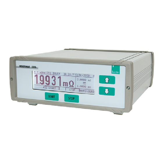
RESISTOMAT Model 2316 ® 4. Controls 4.1. Front panel Front panel with backlit LCD display and integral membrane keypad with tactile feedback 4.1.1 Button functions [START] : In the measurement menu this button starts a measurement In the Configuration menu this button is assigned different functions depending on the text shown on the display above the button (soft key). -
Page 22: Rear Panel
� � Connector shell : PE (protective ground) potential � Mating connector: burster model 9900-V172 � Note: The current branch is protected by a fuse View towards 6.3 x 32 [mm] 10AFF. (rear side of unit) socket - I is at FE potential Caution! Only one measurement input must be used at any one time. - Page 23 RESISTOMAT Model 2316 ® RS232 interface Digital GND (grounded internally) connected in 9-pin min sub-D female instrument connector Connector shell : PE potential View towards socket Mating connector: Model 9900-V209 Matching data cable: Model 9900-K333 Digital I/O Function Function Relay <, NO contact Not used Relay...
- Page 24 RESISTOMAT Model 2316 ® Page 24...
-
Page 25: Operating Instructions In Brief
RESISTOMAT Model 2316 ® 5. Operating instructions in brief After switch on the instrument, the operating language can be selected in the instrument identification menu. Pressing both arrow buttons simultaneously opens the configuration program. ENTER confirms the selected menu option. ESC can be used to return from any option in the configuration menu back to the next menu option down. - Page 26 RESISTOMAT Model 2316 ® �������������� ��������������������������� ������������ ������������������������ ���������������������������������� ���������������������� ��������������������������� ��������������������� �������������� ����������������������� ������������������������ �������������� ���������������� ����������������������� ���������������������� ������������ ������ ��������� ������������������������� ������������������ ������������������������ ������������� ������������������ ����������� ������������������������� ��������� ������������������������� ������������������������ ������������������������ ������ ����������������������� ��������������� ������������ ������������� ��������������� ����������������������������� ������������...
-
Page 27: Operation
RESISTOMAT Model 2316 ® 6. Operation Meaning of the individual display segments temperature display device program time constant M = manual 0 ... 15 of current source A = automatic measurement Z1, Z2, Z3 status line mode SINGLE measuring range CONT temperature coefficient M = manual... -
Page 28: Setup Menu
RESISTOMAT Model 2316 ® Start-up menu The first menu is displayed after power up: RESISTOMAT 2316 VERSION: SERIAL NUMBER SOFTWARE VERSION CAL-NUMBER LANGUAGE TEST If LANGUAGE is not pressed within 3 seconds, the meter goes automatically into the Measure- ment menu. -
Page 29: Configuration Menu
RESISTOMAT Model 2316 ® 6.3 Configuration menu If the buttons are pressed simultaneously, the instrument goes into the configuration state and displays menu 5. Menu 5 has three pages. ↓ MEASURING RANGE 20 mΩ LIMIT VAL. 10.000 mΩ, 20.000 mΩ LOAD RESISTIVE LOAD: Z1 MEASURING MODE... -
Page 30: Measurement Menu
RESISTOMAT Model 2316 ® Measurement menu Measurement mode M 20 kOhm SINGLE A 100.0 C° TC ± 1500 15.000 kΩ 19.437 kΩ > 10.000 kΩ 0 START STOP AUTOZERO Limits and the evaluation result are only displayed when the comparator is enabled. When a measurement is in progress, the measurement counter increments from 0 to 9, changing whenever a new measurement result is available. -
Page 31: Description Of The Individual Setup Menus
RESISTOMAT Model 2316 ® Description of the individual setup menus 6.5.1 Measuring range ↓ SELECT MEASURING RANGE AUTOMATIC (2 mOhm to 200 kOhm) 2 mOhm 20 mOhm 200 mOhm MENU 10 ENTER ESCAPE MEAS RANG Selection bar has inverse display. Press to move selection bar, ENTER to select, and ESC to return to menu 5 without making a change. -
Page 32: Limits
RESISTOMAT Model 2316 ® ↑ SELECT MEASURING RANGE 20 kOhm 200 kOhm MENU 10 ENTER ESCAPE MEAS RANG Selection bar has inverse display. Press to move selection bar, ENTER to select. Press ESC to return to menu 5 without making a change. The arrow in the top right corner ↑ indicates that this is the last menu page. -
Page 33: Load Selection
RESISTOMAT Model 2316 ® 6.5.3 Load selection SELECT LOAD RESISTIVE LOAD: Z1 INDUCTIVE LOAD: Z2 INDUCTIVE LOAD: Z3 MENU 30 ENTER ESCAPE LOAD Selection bar has inverse display. Press to move selection bar, ENTER to select and return to menu 5, and ESC to return to menu 5 without making a change. Selection of LOAD / TIME CONSTANTS Z1, Z2, Z3 This is used to select the time constant Z of the current regulator: Z1 is set for purely resistive devices under test. -
Page 34: Handling Inductive Loads
RESISTOMAT Model 2316 ® 6.5.3.1 Handling inductive loads e.g. reactors, cables on reels, motors, coils, transformers Safety instructions • The instrument has two measurement inputs connected in parallel; only one of these inputs must be used at any one time. No leads must be plugged into the unused connector for safety reasons. - Page 35 RESISTOMAT Model 2316 ® The circuit diagram for the protection circuit is shown below. The diode provides a short-circuit for an induction current and discharges an inductance down to a residual voltage of about 3 V. Even though particularly high-power diodes are used, sometimes there may be a problem at the end of the measurement (when disconnecting) if the device under test has a particularly high inductance.
-
Page 36: Measurement Mode
RESISTOMAT Model 2316 ® 6.5.4 Measurement mode SELECT MEASURING MODE CONTINUOUS SINGLE SHOT ALTERNATING COOLING CURVE MENU 40 NEXT ESCAPE MEAS MODE SELECT MEASURING MODE FAST MEASURE MENU 40 NEXT ESCAPE MEAS MODE 6.5.4.1 Continuous operation ARITHMETIC AVERAGING CONTIN. MEASUREMENT AVERAGE VAL FRM 3 MEAS. -
Page 37: Single Shot
RESISTOMAT Model 2316 ® 6.5.4.2 Single shot MEASURING MODE: SINGLE SHOT N-TH MEAS VAL AFTER START WILL EVALUATED MENU 42 CHANGE ESCAPE CONTINUO Single shot means that although all measurements are displayed, only the n’th measurement reading is saved and compared with the limits (comparator). Then the current source is switched off. -
Page 38: Alternating Measurement Mode
RESISTOMAT Model 2316 ® 6.5.4.3 Alternating measurement mode MEASURING MODE: ALTERNATE AVERAGE VAL FROM3 MEAS. VALS MENU 44 CHANGE ESCAPE ALT MEAS Alternating measurement mode means that the test current is switched on when the START but- ton is pressed and not switched off finally until the STOP button is pressed. The current source is switched on and off continuously during the measurement to suppress any thermal EMFs, so that the instrument remains permanently correctly “zeroed”. -
Page 39: Cooling Curve
RESISTOMAT Model 2316 ® 6.5.4.5 Cooling curve The Cooling curve measurement mode is allowed in conjunction with all times constants, and manual and automatic zero offset. It is not allowed, however, in conjunction with comparator, automatic measuring range and au- tomatic temperature compensation. - Page 40 RESISTOMAT Model 2316 ® MEASUREMENT MODE COOLING CURVE INTERVAL TIME: END TIME: 0100 S DISCARD 0 MEAS VALS AFTER START AVERAGE VAL FROM 2 MEAS. VALS → MENU 43 ESCAPE COOL The cursor sits over the first zero. Pressing increases or decreases the numerical value, while →...
- Page 41 RESISTOMAT Model 2316 ® M 2 mOhm COOL 1.4379 mΩ ACT: 24s MAX: 100s 0 START STOP AUTOZERO START launches the actual resistance measurement (with AUTOZERO set, there may be a slight delay of about 0.25 s to allow for the zero measurement) and the measurements are saved in the data logger (up to 999 values).
-
Page 42: Temperature Compensation
RESISTOMAT Model 2316 ® 6.5.5 Temperature compensation SELECT TEMPERATURE COMPENSATION COPPER (+3930 PPM/K) ALUMINIUM (+4030 PPM/K) BRASS 63 (+1500 PPM/K) MENU 50 ENTER ESCAPE TEMP.COMP Selection bar has inverse display. Press to move selection bar, ENTER to select, and ESC to return to the menu. -
Page 43: Autozero / Man-Zero
RESISTOMAT Model 2316 ® 6.5.6 Autozero / Man-Zero SELECT AUTOZERO AUTOZERO MAN ZERO MENU 60 ENTER ESCAPE ZERO CFG Press to move selection bar, ENTER to select, and ESC to return to the measurement menu. When Autozero is enabled, after pressing the START button the voltage across the U terminals is detected and zeroed n times, initially with the current still off. -
Page 44: Device Program
RESISTOMAT Model 2316 ® 6.5.7 Device program SELECT DEVICE PROGRAM PRESENT DEVICE PROGRAM: 0 PROGRAM COPY INITIALIZE SELECTED DEVICE PROGRAM INITIALIZE COMPLETE DEVICE MENU 70 CHANGE ESCAPE MEAS PROG Pressing the CHANGE button displays the following screen: SELECT DEVICE PROGRAM PRESENT DEVICE PROGRAM: PROGRAM COPY INITIALIZE SELECTED DEVICE PROGRAM... -
Page 45: Comparator
RESISTOMAT Model 2316 ® 6.5.8 Comparator SELECT COMPARATOR MODE COMPARATOR ON, RELAY ON COMPARATOR ON, RELAY OFF COMPARATOR OFF MENU 80 ENTER ESCAPE COMPARAT. The following menu is displayed if the comparator is enabled: SELECT COMPARATOR RESET MODE STATIC DYNAMIC MENU 81 ENTER ESCAPE... -
Page 46: Contrast
RESISTOMAT Model 2316 ® 6.5.9 Contrast CONTRAST SETTING PRESENT SETTING: 50 DESIRED CONTRAST: 50 MENU 90 CHANGE ESCAPE CONTRAST The following screen is displayed after pressing the CHANGE button: CONTRAST SETTING PRESENT SETTING: 50 DESIRED CONTRAST: 50 → MENU 90 ESCAPE CONTRAST ... -
Page 47: Temperature Sensor
RESISTOMAT Model 2316 ® 6.5.10 Temperature sensor SELECT TEMPERATURE SENSOR PT-100 PT-100 INDIV PYROMETER MANUAL MENU 100 NEXT ESCAPE TEMP SENS If PT-100 is selected, the following screen is displayed for information; values cannot be changed. PT-100 COEFFICIENTS (DIN EN 60751) (FIX) R(T) = R0 * (1 + A*T + B*T R0 = 100.0 A = 3.9083E-03... - Page 48 RESISTOMAT Model 2316 ® The following screen is displayed if PYROMETER is selected: PYROMETER CALIBRATION LOWER TEMP: °C (MAX 999.9 °C) LOWER VOLT.: 0.00 V (MAX 10 V) UPPER TEMP: 100,0 °C (MAX 999.9 °C) UPPER VOLT.: (MAX 10 V) MENU 103 CHANGE ESCAPE...
-
Page 49: Display Counts
RESISTOMAT Model 2316 ® The following screen is displayed if MANUAL is selected: SETUP AMBIENT TEMPERATURE LOWER TEMP: 20.00 °C (0.0 ... 100.0 °C) MENU 104 CHANGE ESCAPE MANUAL Pressing CHANGE displays the following screen: SETUP AMBIENT TEMPERATURE LOWER TEMP: 020.00 °C (0.0 ... -
Page 50: Self-Test
RESISTOMAT Model 2316 ® 6.5.12 Self test The instrument has numerous built-in diagnostic functions, which you can use to check whether the instrument is working correctly, and for self-help troubleshooting. ↓ DEVICE TEST PLC & I/O - TEST SUPPLY VOLTAGE TEST CURRENT SOURCE TEST AMPLIFIER TEST MENU 120... - Page 51 RESISTOMAT Model 2316 ® The following screen appears after selecting "SUPPLY VOLTAGE TEST". SUPPLY VOLTAGE TEST PASS MENU 122 ESCAPE U-TEST If the screen don't appears one of internal supply voltages are off. Switch the device off and on and try it again. The following screen appears after selecting "CURRENT SOURCE TEST".
- Page 52 RESISTOMAT Model 2316 ® The following display appears after selecting „Amplifier test“: AMPLIFIER TEST PLEASE REMOVE TEST LEADS NOTE THE SAFETY INSTRUCTIONS PRESS START AFTERWARDS MENU 124 START ESCAPE AMP-TEST The following display appears after selecting „Current source test“: AMPLIFIER TEST PASS MENU 124 START...
-
Page 53: Data Output
RESISTOMAT Model 2316 ® 6.5.13 Data output SELECT DATA OUTPUT PRINTER MENU 130 ENTER ESCAPE DATA OUTP to move the selection bar, ENTER to select. Always print Setting PRINTER as data output means that every valid measurement is sent to the printer. Depending on the instrument setup, a large amount of data can accrue, so please set the instrument and printer to the largest possible common transmission rate. -
Page 54: Access To Password
RESISTOMAT Model 2316 ® 6.5.14 Access to password This is where one specifies whether the meter user can access all functions and settings of the instrument, or whether his access options are limited. On delivery, access is enabled for all set- tings. - Page 55 RESISTOMAT Model 2316 ® The following screen appears after selecting “CHANGE ACCESS”. ALLOW ACCESS TO START, STOP START, STOP, MEASURING RANGE START, STOP, MEASURING RANGE, LIMIT VALUES FULL ACCESS MENU 142 ENTER ESCAPE ACCESS The current selection is highlighted. Press to move selection bar, ENTER to select.
-
Page 56: Interface
RESISTOMAT Model 2316 ® 6.5.15 Interface ↓ CONFIGURATION SERIAL INTERFACE BAUD RATE: 9600 DAT-FORMAT: 8DATA, 1STOP, NO PARITY ADDRESS: GROUP: MENU 150 CHANGE ESCAPE INTERFACE ↓ to move the selection bar, CHANGE to select. shows that there is a second page: CONFIGURATION SERIAL INTERFACE BAUD RATE: 9600...................... -
Page 57: Reference Temperature
RESISTOMAT Model 2316 ® 6.5.16 Reference temperature REFERENCE TEMPERATURE PRESENT SETTING: 20.0 °C DESIRED TEMPERATURE: 20.0 °C (10°C ... 30°C) MENU 160 CHANGE ESCAPE REF.TEMP Pressing the „CHANGE“ button displays the following screen: SELECT REFERENCE TEMPERATURE PRESENT SETTING: 20.0 °C DESIRED TEMPERATURE: 20.0 °C (10°C ... -
Page 58: Reference Length
RESISTOMAT Model 2316 ® 6.5.17 Reference length REFERENCE LENGTH PRESENT SETTING: 1.00 m DESIRED SETTING: 1.00 (0.1 ... 99.99 m) SELECTION OF UNIT: MENU 170 CHANGE ESCAPE REF.LENG , ENTER to select. The default reference length is 1m. The following screen is displayed after pressing the CHANGE button: SELECT REFERENCE LENGTH PRESENT SETTING: 1.00 m... - Page 59 RESISTOMAT Model 2316 ® UNITS PRESENT SETTING: 1.00 m DESIRED SETTING: 1.00 (0.1 m ... 99.99 m) SELECTION OF UNIT: MENU 170 CHANGE ESCAPE REF.LENG , ENTER to select. SELECT REFERENCE LENGTH PRESENT SETTING: 1.00 m DESIRED SETTING: 1.00 (0.1 m ... 99.99 m) SELECTION OF UNIT: →...
-
Page 60: Measurement Current Selection
RESISTOMAT Model 2316 ® 6.5.18 Measurement current selection MEASUREMENT CURRENT HIGH MENU 180 ENTER ESCAPE MEAS CURR Depending upon environment of the measurement place strong electromagnetic fields can give a destabilise value in the display. To put things right it gives the possibility of the averaging of some measurement values or to increase the measurement current whereby you increase the signal - to-noise ratio. -
Page 61: Controlling The Instrument Remotely
RESISTOMAT Model 2316 ® 7. Controlling the instrument remotely Controlling the instrument via the PLC interface Digital I/O Function Function Relay <, NO contact Not used Relay =, NO contact PLC output Device program saved ok Relay >, NO contact Relay Relay common contact PLC output... -
Page 62: Controlling The Instrument Via The Rs232 Interface
RESISTOMAT Model 2316 ® PLC output (circuit diagram) PLC input (circuit diagram) Pin 18 +24V from PLC 1.8 kΩ (20 V ... 24 V ... 30 V) Pin xx U= 20 V ... 24 V ... 30 V ≤ 150 mA Pin xx for all outputs ext. -
Page 63: Interface Parameters
RESISTOMAT Model 2316 ® 7.2.2 Interface parameters The interface parameters can be set in menu 150 Interface. Baud rate: 300, 600, 1200, 2400, 4800, 9600 , 19200, 38400, 56000, 57600 Data bits: 7 or 8 Stop bits: or 2 Parity: none , even, odd Block check: Enabled... -
Page 64: Selection With Response
RESISTOMAT Model 2316 ® (2) “fast selection” In this case addressing is combined with the command. This saves a communications step if you want to exchange data with several devices (via RS485) (see communications example in section 8.16) When establishing a connection, the control station can either specify a slave station in order to set up a connection i.e. -
Page 65: Fast Selection
RESISTOMAT Model 2316 ® 7.2.6 Fast selection Instead of „selection with response“, the master station can send a selection supervisory sequence without <ENQ>. The master station calls up a secondary station as the slave station. It then shifts directly into data transfer without waiting for the acknowledge response from the secondary station. -
Page 66: Data Transfer
RESISTOMAT Model 2316 ® 7.2.8 Data transfer After establishing the connection, the data is transferred in accordance with the rules of subcat- egory A4. The master station begins the transmission with <STX>, then sends the relevant data, and terminates the data block with <ETX>. The <ETX> character is followed by the optional block check character <BCC>. -
Page 67: Communication Using „Fast Selection
0000po<ENQ> The 2316 with group address 0 and user address 0 is required to send all responses waiting to be sent 2316 sends response, with block check OFF: <STX>RESISTOMAT 2316,3A,0123456789,V200401,09.12.2004,1<LF><ETX> for type 2316-V0001 or 1A for type 2316-V0000 This is the correct response to the *idn? command Controller sends: <ACK>... -
Page 68: General Information
RESISTOMAT Model 2316 ® General information 7.3.1 Interface watchdog timer 7.3.1.1 Timer A (response timer) Timer A is used by RESISTOMAT 2316 to protect itself from an invalid response or no re- ® sponse. • Start: Timer A is started after data transfer has been terminated with <ETX>. The instrument waits for an acknowledgement by the master. -
Page 69: Scpi Commands
RESISTOMAT Model 2316 ® 8. SCPI commands General information • Command sections contained in [ ] are optional. • Commands have a long form and short form. Both forms are valid. The short form is written in upper-case. The long form is added in lower-case. •... -
Page 70: Functions That Have Changed
RESISTOMAT Model 2316 ® 8.1.2 Functions that have changed • Setting the group and user address via the interface has led to problems in the past on the RESISTOMAT 2318 and is therefore no longer possible. The instrument responds with ®... -
Page 71: List Of Old Commands
RESISTOMAT Model 2316 ® 8.1.3 List of old commands Command Meaning in 2318 Meaning in 2316 MEASure[:SCALar:RESistance:DC] Stop, start, Not implemented, retrieve measurement instrument returns NAK READ[:SCALar:RESistance:DC]? Stop, start, Not implemented, retrieve measurement instrument returns NAK FETCh[:SCALar:RESistance:DC] Retrieve measurement Implemented INITiate[:IMMediate] Start measurement Implemented... -
Page 72: Scpi Registers
RESISTOMAT Model 2316 ® SCPI registers Error/Event Queue The bits labeled * are used. QUEStionable Status VOLTage CURRent TIME POWer * TEMPerature FREQuency PHASe MODulation * CALIbration * RESistor Available to designer Available to designer Available to designer INSTrument Summary * Command Warning NOT USED OPERation Status... -
Page 73: Access Subsystem
RESISTOMAT Model 2316 ® ACCess Subsystem 8.3.1 ACCess:LEVel DESCRIPTION: Sets the access levels. SYNTAX: ACCess:LEVel P1 Meaning of parameter Pn Parameter Meaning Value → Permitted access Start and stop permitted → Start, stop and measuring-range selection permitted → Start, stop, measuring-range selection and comparator limits permitted →... -
Page 74: Display Subsystem
RESISTOMAT Model 2316 ® DISPlay Subsystem 8.4.1 DISPlay:CONTrast DESCRIPTION: Can be used to adjust the LCD contrast. SYNTAX: DISPlay:CONTrast P1 Meaning of parameter Pn Parameter Meaning Value LCD contrast Floating-point value between 0.0 and 1.0 → minimum contrast → maximum contrast QUERY FORM: DISPlay:CONTrast? RESPONSE:... -
Page 75: Calculate Subsystem
RESISTOMAT Model 2316 ® CALCulate Subsystem 8.5.1 CALCulate:LIMit:STATe DESCRIPTION: Enables or disables the comparator function. SYNTAX: CALCulate:LIMit:STATe P1 Meaning of parameter Pn Parameter Meaning Value → Comparator 1 or ON Comparator function enabled → on/off 0 or OFF Comparator function disabled QUERY FORM: CALCulate:LIMit:STATe? RESPONSE:... -
Page 76: Calculate:limit:relais
RESISTOMAT Model 2316 ® 8.5.2 CALCulate:LIMit:RELais DESCRIPTION: Enables or disables the relay function. SYNTAX: CALCulate:LIMit:RELais P1 Meaning of parameter Pn Parameter Meaning Value → Relay function 1 or ON Relay function enabled → on/off 0 or OFF Relay function disabled QUERY FORM: CALCulate:LIMit:RELais? RESPONSE:... -
Page 77: Calculate:limit:lower
RESISTOMAT Model 2316 ® 8.5.4 CALCulate:LIMit:LOWer DESCRIPTION: Sets the lower comparator limit. This value is not adopted, however, until the CALCulate:LIMit:ACKNowledge? command is received, once the upper comparator limit has also been transferred using the CALCulate:LIMit:UPPer command. SYNTAX: CALCulate:LIMit:LOWer P1 Meaning of parameter Pn Parameter Meaning Value... -
Page 78: Calculate:limit:acknowledge
RESISTOMAT Model 2316 ® 8.5.6 CALCulate:LIMit:ACKNowledge? DESCRIPTION: Adopts the comparator limits. This command causes those comparator limits to be adopted that were previously transferred using the two commands CALCulate:LIMit: LOWer (lower comparator limit) and CALCulate:LIMit:UPPer (upper comparator limit). SYNTAX: CALCulate:LIMit:ACKNowledge? No parameter QUERY FORM: Query form only... -
Page 79: Calculate:limit:math[Expression]
RESISTOMAT Model 2316 ® 8.5.8 CALCulate:MATH[:EXPRession] DESCRIPTION: Switches the measurement display between Ohm and Ohm/m SYNTAX: CALCulate:MATH[:EXPRession] P1 Meaning of parameter Pn Parameter Meaning Value → Display in Ohm or Ohm/m Measurement display in Ohm → OHM/M Measurement display in Ohm/m →... -
Page 80: Scale Subsystem
RESISTOMAT Model 2316 ® SCALE Subsystem 8.6.1 SCALE:VOLTage DESCRIPTION: Scales the voltage input from the pyrometer. SYNTAX: SCALe:VOLtage P1,P2,P3,P4 Meaning of parameter Pn Parameter Meaning Value Lower voltage Floating-pt value optionally with units (UV, MV, V, KV, MAV) Upper voltage Floating-pt value optionally with units (UV, MV, V, KV, MAV) Lower temperature Floating-point value optionally with units (C, CEL) -
Page 81: Scale:pt100
RESISTOMAT Model 2316 ® 8.6.2 SCALE:PT100 DESCRIPTION: Sets the Pt100 coefficients for positive temperatures. SYNTAX: SCALe:PT100 P1,P2,P3 Meaning of parameter Pn Parameter Meaning Value Pt100 coefficient R0 Floating-point value Pt100 coefficient a Floating-point value Pt100 coefficient b Floating-point value Equation: Rt = R0 * (1 + a * t + b * t QUERY FORM: SCALe:PT100? -
Page 82: Hcopy Subsystem
RESISTOMAT Model 2316 ® HCOPy Subsystem 8.7.1 HCOPy:DESTination DESCRIPTION: Sets the function of the serial port. Printer output or PC interface. SYNTAX: HCOPy:DESTination P1 Meaning of parameter Pn Parameter Meaning Value → Function of the serial port PRINTER Serial port is the printer output →... -
Page 83: Ccurve:time:delta
RESISTOMAT Model 2316 ® 8.8.2 CCURve:TIME:DELTa DESCRIPTION: Sets the time interval between measurements (delta time) on the cooling curve. SYNTAX: CCURve:TIME:DELTa P1 Meaning of parameter Pn Parameter Meaning Value Time interval between measurements on cooling curve Integer between 1 and 9999 in seconds QUERY FORM: CCURve:TIME:DELTa? RESPONSE:... -
Page 84: Ccurve:time:charge
RESISTOMAT Model 2316 ® 8.8.4 CCURve:DATA DESCRIPTION: Can be used to read the individual entries in the data logger. SYNTAX: CCURve:DATA? Meaning of parameter Pn Parameter Meaning Value Entry number in the data logger Numerical value QUERY FORM: Query form only RESPONSE: A1,A2,A3,A4 Meaning of response An... -
Page 85: Ccurve:initiate
RESISTOMAT Model 2316 ® 8.8.6 CCURve:INITiate DESCRIPTION: Starts the cooling-curve measurement. SYNTAX: CCURve:INITiate No parameter QUERY FORM: No query form NOTE: Command not allowed in calibration mode. Command not allowed when measurement running. Command only allowed in cooling-curve mode. 8.8.7 CCURve:ABORt DESCRIPTION: Stops the cooling-curve measurement. -
Page 86: Trace Subsystem
RESISTOMAT Model 2316 ® TRACe Subsystem 8.9.1 TRACe:DATA:LENGth DESCRIPTION: Transfers and queries the reference length. SYNTAX: TRACe:DATA:LENGth P1 Meaning of parameter Pn Parameter Meaning Value Reference length Floating-pt value optionally with units (UM, MM, CM, DM, M, KM) QUERY FORM: TRACe:DATA:LENGth? RESPONSE: Meaning of response An... -
Page 87: Initiate[Immediate]
RESISTOMAT Model 2316 ® 8.10.2 INITiate[IMMediate] DESCRIPTION: Starts a measurement that has been stopped. SYNTAX: INITiate[IMMediate] No parameter QUERY FORM: No query form NOTE: Command not allowed in calibration mode. Command not allowed when measurement already started. For speed reasons there is also a non-SCPI-compliant short form: IN 8.10.3 INITiate:CONTinuous DESCRIPTION: Switches between single and continuous measurement mode. -
Page 88: Fetch
RESISTOMAT Model 2316 ® 8.10.4 FETCh? DESCRIPTION: Can be used to retrieve one measurement. SYNTAX: FETCh? No parameter QUERY FORM: Query form only RESPONSE: A1, A2 Meaning of response An Response Meaning Value Measured resistance value Floating-point value with units Comparator result, if comparator enabled <, = or >... -
Page 89: System:language
RESISTOMAT Model 2316 ® 8.11.2 SYSTem:LANGuage DESCRIPTION: Sets and queries the operating language. SYNTAX: SYSTem:LANGuage P1 Meaning of parameter Pn Parameter Meaning Value Operating language GERMAN -> German operating language ENGLISH -> English operating language FRENCH -> French operating language ITALIAN ->... -
Page 90: System:error[Next]
RESISTOMAT Model 2316 ® 8.11.4 SYSTem:ERRor[:NEXT]? DESCRIPTION: Can be used to query any errors that may have occurred at the instru- ment. SYNTAX: SYSTem:ERRor[:NEXT]? No parameter QUERY FORM: Query form only RESPONSE: Meaning of response An Response Meaning Value Error status 0, NO ERROR: No errors present. -
Page 91: Status Subsystem
RESISTOMAT Model 2316 ® 8.12 STATus Subsystem 8.12.1 STATus:PRESet DESCRIPTION: Resets both the Operation Status Enable register and the Questionable Status Enable register to 0. SYNTAX: STATus:PRESet No parameter QUERY FORM: No query form 8.12.2 STATus:OPERation:ENABle DESCRIPTION: Sets the Operation Status Enable register. SYNTAX: STATus:OPERation:ENABle P1 Meaning of parameter Pn... -
Page 92: Status:questionable:enable
RESISTOMAT Model 2316 ® 8.12.3 STATus:QUEStionable:ENABle DESCRIPTION: Sets the Questionable Status Enable register. SYNTAX: STATus:QUEStionable:ENABle P1 Meaning of parameter Pn Parameter Meaning Value Contents of the 16-bit Operation Status Enable register Decimal value between 0 and 32767 QUERY FORM: STATus:QUEStionable: ENABle? RESPONSE: Meaning of response An... -
Page 93: Status:questionable:condition
RESISTOMAT Model 2316 ® 8.12.5 STATus:QUEStionable:CONDition? DESCRIPTION: Reads the Questionable Status Condition register. SYNTAX: STATus:QUEStionable:CONDition? No parameter QUERY FORM: Query form only RESPONSE: Meaning of response An Response Meaning Value Contents of the 16-bit Questionable Decimal value Status Condition register between 0 and 32767 NOTE: For speed reasons there is also a non-SCPI-compliant short form: S:Q:C? -
Page 94: Status:questionable:[Event]
RESISTOMAT Model 2316 ® 8.12.7 STATus:QUEStionable:[EVENt]? DESCRIPTION: Reads the Questionable Status Event register. SYNTAX: STATus:QUEStionable:[EVENt]? No parameter QUERY FORM: Query form only RESPONSE: Meaning of response An Response Meaning Value Contents of the 16-bit Questionable Status Event register Decimal value between 0 and 32767 NOTE: Error remains stored effected to inquiry. -
Page 95: Sense Subsystem
RESISTOMAT Model 2316 ® 8.13 SENSe Subsystem 8.13.1 SENSe:TCOMpensate DESCRIPTION: Sets the type of temperature sensor for the temperature compensation is detected. SYNTAX: SENSe:TCOMpensate P1 Meaning of parameter Pn Parameter Meaning Value How the -> Manual temperature input temperature PT100 ->... -
Page 96: Sense:tcompensate:state
RESISTOMAT Model 2316 ® 8.13.2 SENSe:TCOMpensate:STATe DESCRIPTION: Enables or disables temperature compensation. SYNTAX: SENSe:TCOMpensate:STATe P1 Meaning of parameter Pn Parameter Meaning Value Temperature compensation 1 or ON Enable temperature compensation on or off 0 or OFF Disable temperature compensation QUERY FORM: SENSe:TCOMpensate:STATe? RESPONSE: Meaning of response An... -
Page 97: Sense:tcompensate:temereature:reference
RESISTOMAT Model 2316 ® 8.13.4 SENSe:TCOMpensate:TEMPerature:REFerence DESCRIPTION: Sets the reference temperature for temperature compensation. SYNTAX: SENSe:TCOMpensate:TEMPeratureREFerence P1 Meaning of parameter Pn Parameter Meaning Value Reference temperature for Floating-pt value optionally with units temperature compensation (C or CEL) QUERY FORM: SENSe:TCOMpensate:TEMPerature:REFerence? RESPONSE: Meaning of response An Response... -
Page 98: Sense:tcompensate:tcoefficient:select
RESISTOMAT Model 2316 ® 8.13.5 SENSe:TCOMpensate:TCOefficient:SELect DESCRIPTION: Selects a temperature coefficient for the temperature compensation. SYNTAX: SENSe:TCOMpensate:TCOefficient:SELect P1 Meaning of parameter Pn Parameter Meaning Value Number of the temperature coefficient Numerical value between 1 and 16 -> TEMPCOMP_OFF -> TEMPCOMP_COPPER ->... -
Page 99: Sense:tcompensate:tcoefficient:user:change
RESISTOMAT Model 2316 ® 8.13.6 SENSe:TCOMpensate:TCOefficient:USER:CHANge DESCRIPTION: Can be used to set the user-definable temperature coefficients. SYNTAX: SENSe:TCOMpensate:TCOefficient:USER:CHANge P1, P2, P3 Meaning of parameter Pn Parameter Meaning Value Number of the user-definable TC Numerical value between 9 and 16 TC identifier String with up to 10 characters Value of the TC in ppm Floating-point value... -
Page 100: Sense:fresistance:resolution
RESISTOMAT Model 2316 ® 8.13.7 SENSe:FRESistance:RESolution DESCRIPTION: Sets the resolution of the measurement display. SYNTAX: SENSe:FRESistance:RESolution P1 Meaning of parameter Pn Parameter Meaning Value Resolution of the measurement display 0.0005 -> Low resolution (2000) 0.00005 -> High resolution (20000) QUERY FORM: SENSe:FRESistance:RESolution? RESPONSE: Meaning of response An... -
Page 101: Sense:fresistance:time:constant
RESISTOMAT Model 2316 ® 8.13.9 SENSe:FRESistance:TIME:CONStant DESCRIPTION: Sets the load type of the device under test SYNTAX: SENSe:FRESistance:TIME:CONStant P1 Meaning of parameter Pn Parameter Meaning Value Time constant i.e. load type of device under test T1 -> Resistive load Z1 T2 ->... -
Page 102: Sense:fresistance:range:auto
RESISTOMAT Model 2316 ® 8.13.11 SENSe:FRESistance:RANGe:AUTO DESCRIPTION: Switches between manual and automatic range-selection. SYNTAX: SENSe:FRESistance:RANGe:AUTO P1 Meaning of parameter Pn Parameter Meaning Value Manual or automatic range-selection 1 or ON -> Automatic range-selection 0 or OFF-> Manual range-selection QUERY FORM: SENSe:FRESistance:RANGe:AUTO? RESPONSE: Meaning of response An... -
Page 103: Sense:fresistance:range:upper
RESISTOMAT Model 2316 ® 8.13.12 SENSe:FRESistance:RANGe:UPPer DESCRIPTION: Sets the maximum permitted measuring range for automatic range- selection. SYNTAX: SENSe:FRESistance:RANGe:UPPer P1 Meaning of parameter Pn Parameter Meaning Value Max. measuring range for automatic 2MOHM -> 2 mΩ range range-selection 20MOHM -> 20 mΩ range 200MOHM ->... -
Page 104: Sense:fresistance:range:lower
RESISTOMAT Model 2316 ® 8.13.13 SENSe:FRESistance:RANGe:LOWer DESCRIPTION: Sets the minimum permitted measuring range for automatic range- selection. SYNTAX: SENSe:FRESistance:RANGe:LOWer P1 Meaning of parameter Pn Parameter Meaning Value Min. measuring range for automatic 2MOHM -> 2 mΩ range range-selection 20MOHM -> 20 mΩ range 200MOHM ->... -
Page 105: Sense:fresistance:range:manual
RESISTOMAT Model 2316 ® 8.13.14 SENSe:FRESistance:RANGe:MANual DESCRIPTION: Sets the measuring range for manual range-selection. SYNTAX: SENSe:FRESistance:RANGe:MANual P1 Meaning of parameter Pn Parameter Meaning Value Measuring range for manual 2MOHM -> 2 mΩ range range-selection 20MOHM -> 20 mΩ range 200MOHM -> 200 mΩ range Ω... -
Page 106: Sense:average:count
RESISTOMAT Model 2316 ® 8.13.15 SENSe:AVERage:COUNt DESCRIPTION: Sets the number of measurements to be used for calculating the mean resistance. SYNTAX: SENSe:AVERage:COUNt P1 Meaning of parameter Pn Parameter Meaning Value Number of values used for average Numerical value between 1 and 99 QUERY FORM: SENSe:AVERage:COUNt? RESPONSE:... -
Page 107: Source Subsystem
RESISTOMAT Model 2316 ® QUERY FORM: SENSe:CORRection:OFFSet:AUTO:STATe? RESPONSE: Meaning of response An Response Meaning Value Status of autom. 1 -> Automatic thermal-EMF compensation on Thermal-EMF 0 -> Automatic thermal-EMF compensation off compensation NOTE: Command not allowed in calibration mode. Command not allowed when measurement running. 8.14 SOURce Subsystem 8.14.1 SOURce:CURRent[:LEVel:IMMediate:AMPLitude]... -
Page 108: Ieee-488.2 Commands
RESISTOMAT Model 2316 ® 8.15 IEEE-488.2 commands 8.15.1 *SRE command DESCRIPTION: Sets the Service Request Enable register. SYNTAX: *SRE P1 Meaning of parameter Pn Parameter Meaning Value Contents of the Service Request Enable register Numerical value between 0 and 255 QUERY FORM: *SRE? RESPONSE:... -
Page 109: Ese Command
RESISTOMAT Model 2316 ® 8.15.3 *ESE command DESCRIPTION: Sets the Standard Event Status Enable register. SYNTAX: *ESE P1 Meaning of parameter Pn Parameter Meaning Value Contents of the Standard Event Status register Numerical value between 0 and 255 QUERY FORM: *ESE? RESPONSE: Meaning of response An... -
Page 110: Opc Command
RESISTOMAT Model 2316 ® 8.15.5 *OPC command DESCRIPTION: Sets the device to the Operation Complete Active state (OCAS). SYNTAX: *OPC NOTE: This command has no function on the 2316. No point to it on the serial port with ANSI protocol. 8.15.6 *RST command DESCRIPTION: Sets the device to a defined initial state. -
Page 111: Wai Command
RESISTOMAT Model 2316 ® 8.15.8 *WAI command DESCRIPTION: This command configures the device to handle all commands sequentially. This command has no function on the RESISTOMAT 2316 because com- ® mands are always handled sequentially anyway. The command is merely recognized. -
Page 112: Idn? Command
RESISTOMAT Model 2316 ® 8.15.10 *IDN? Command DESCRIPTION: Retrieves various information for device identification. SYNTAX: *IDN? No parameter QUERY FORM: Query form only RESPONSE: A1, A2, A3, A4, A5, A6 Meaning of response An Response Meaning Value Device identification RESISTOMAT 2316 ®... -
Page 113: Programming Examples
RESISTOMAT Model 2316 ® 8.16 Programming examples QBasic examples These two examples were written using Quick-Basic, and in both methods shown retrieve the info string. 8.16.1 Communication using „selection with response“ REM *********************************************************************** REM ** REM ** 2316_1.bas Developped by:MN,Li REM ** Changed by:CS REM **... - Page 114 RESISTOMAT Model 2316 ® PRINT „————>>>>> Connecting Device with adress 1..“ REM ** Sending „selection supervisory sequence“ and pick up answer send EOT first to end other (probably unanswered) enquiries PRINT #3, EOT$ + „0000“ + „sr“ + ENQ$ REM clear answer string ant$ = „“...
-
Page 115: Communication Using „Fast Selection
RESISTOMAT Model 2316 ® 8.16.2 Communication using „fast selection“ REM *********************************************************************** * REM ** REM ** 2316_2.bas Developped by:MN,Li REM ** Changed by:CS REM ** Prog. language: Qbasic 4.5 REM ** Communication exe-File created with QB 4.5 REM ** with fast selection date: 09.12.2004 REM ** example: ask for ID-string with fast selection Rem *********************************************************************** *... - Page 116 RESISTOMAT Model 2316 ® REM++++++++++++++++++++++++++++++++++++++++++++++++++++++++++++++++++ REM Ask Device (adr 0) for ID-String with Mode „fast selection“ REM (one of the two communication modes) REM All commands in the user manual are described in this mode REM++++++++++++++++++++++++++++++++++++++++++++++++++++++++++++++++++ PRINT „————>>>>> Connecting Device with adress 0..“ REM send EOT first to end other (probably un-answered) enquiries (strongly recommended) PRINT #3, EOT$ REM Create and send command...
-
Page 117: Programming Steps To Read In A Value
For the end go to line 21. Measuring end: 21. PC: <EOT>0000sr<STX>abor<LF><ETX> 22. 2316: <ACK> 23. PC: <EOT> Hint : At our homepage http://www.burster.com/software.html you can download free of charge the software "Serial Console" where you can check the different instructions. Page 117... -
Page 118: Maintenance, Customer Service, Shipping, Cleaning
Factory warranty burster guarantees trouble-free operation of the instrument for 24 months after delivery. Any repairs required during this time will be made without charge. Damage caused by improper use of the equipment is not covered by the warranty. -
Page 119: Appendix
RESISTOMAT Model 2316 ® 10 . Appendix 10.1 Technical data Only values that include tolerances or limits are data covered by the warranty. Values that do not include tolerances are provided for information and do not come under the warranty. The instrument is designed for easy servicing and is housed in a rugged metal case. - Page 120 RESISTOMAT Model 2316 ® Inductive loads: three different regulator parameters preset to give optimum speed, protection circuit, discharge of inductance Measurement fault: oscillation detection open-circuit detection Pt100 absence detection Warm-up time: < 15 min until error tolerances are reached Auxiliary power: 100 ...
-
Page 121: Calibration
RESISTOMAT Model 2316 ® 10.2 Calibration The instrument is calibrated digitally. PC software 2316-P001 (purchased separately) and a range of series 1240 calibration resistances are required for the calibration. 10.3 Error messages and troubleshooting Fault Possible cause Remedial action Display does not Mains fuse blown. - Page 122 RESISTOMAT Model 2316 ® Internal device errors After power-up, the instrument checks the calibration data in the data memory, the non-volatile variables in the data memory and the EEPROM on the analog card. Since more than one error can occur at once, the errors are binary coded and displayed on the LCD in the event of an error. Bit 0 set means that non-volatile data in the RAM has been lost.
Need help?
Do you have a question about the RESISTOMAT 2316 and is the answer not in the manual?
Questions and answers