
Related Manuals for Burster 9181


Summary of Contents for Burster 9181
- Page 1 MULTIFUNCTION DIGITAL PANEL METER FAST ADQUISITION MODEL 9181 MODBUS-RTU PROTOCOL COMPATIBLE INSTRUCTIONS MANUAL Code: 30727148 Edition: October 2001 Valid for models with software version M-1...
- Page 2 • DIMENSIONS With a fully MODULAR DESIGN, it is possible to implement a Models Typ 9180 & Typ 9181 96x48x120 mm DIN 43700 wide variety of applications by only adding the adequate Model Typ 9186 96x48x60 mm DIN 43700 options.
- Page 3 DIGITAL PANEL INSTRUMENT DIGIMASTER MODEL 9181 INDEX 1 . MODEL 9181 OVERVIEW ............................4/ 5 1.1. – KEYBOARD AND DISPLAY DESCRIPTION....................6/ 7 2 . GETTING STARTED ................................ 8 2.1 – POWER AND CONNECTORS........................9/ 10 2.2 – INTRODUCTION TO THE PROGRAMMING MODE ...................11/ 12 2.3 –...
- Page 4 RS232C or RS485 OUTPUT BOARD ANALOG OUTPUT BOARD SETPOINTS OUTPUT BOARD INPUT BOARD CASE WITH POWER FIXING CLIPS FILTER CIRCUIT FRONT-PANEL COVER DISPLAY MAIN BOARD...
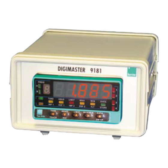
- Page 5 PEAK, VALLEY, PEAK-PEAK values and also the rate @ 555 / second. comparison with SETPOINTS (selectable). The 9181 is an instrument to measure and control with direct The basic instrument is made with main board, supply filter, indication in engineering units. The multifunction input board input board and display (see figure on page.
- Page 6 FRONT-PANEL FUNCTIONS IN RUN MODE MAIN DISPLAY Reads the input variable AUXILIARY DISPLAY Positive " " or negative "-" signal LED 1 Indicates activation/display PROG setpoint 1 RUN LED LED 2 RUN mode indication Indicates activation/display setpoint 2 TARE LED R UN LED 3 TAR E...
- Page 7 FRONT-PANEL FUNCTIONS IN PROG MODE MAIN DISPLAY Reads programming parameters AUXILIARY DISPLAY Indicates program module FLT LED PROG Indicates input filter programming. A and B LED's Indicates program module STORE LED letter. Indicates exit from de program mode with data memory storage.
-
Page 8: Getting Started
Accessories for wiring connections (removable plug-in connectors and fingertip). Input type and connections (Pages 13, 14, 15 and 16) Wiring label sticked to the 9181 The instrument provides four excitation voltages to supply Set of engineering units labels the transducer 2,2V, 5V , 10V or 24V, are set up at factory for 10V. - Page 9 2.1 - Power supply Should any hardware modification be performed, remove the electronics from the case as shown in figure 9.1. 115/230 V AC: The instruments with 115/230 V AC power, are shipped from the factory for 230 V AC (USA market 115 V AC), see figure 9.2.
-
Page 10: Installation
POWER CONNECTION-CN1 INSTALLATION To meet the requirements of the directive EN61010-1, where the unit is permanently connected to the mains supply it is obligatory to install a circuit breaking device easy reachable to the operator and clearly marked as the disconnect device. WARNING In order to guarantee electromagnetic compatibility, the following guidelines for cable wiring must be followed:... -
Page 11: Programming Instructions
2.2 – Programming instructions Connect the instrument to the main supply. During a few The 3, 4 and 5 modules will be omitted if the 2RE option, seconds al segments will turn on as a checking of the good analog option or serial option are not installed. The function of the device. - Page 12 The programming instructions are composed by a general description and a series of step-by-step instructions to be followed sequentially. Each menu step is represented by an illustration of the display and keyboard module with indicators (display and LED's), reference [page number . figure number] and a text describing the action of each key at that step. [page nº/figure nº] Mnemo In the step-by-step instructions, you are given the action of the three buttons mainly used to program data.
-
Page 13: Input Configuration
If the 9181 should work with mV (Load-Cell, shunt or similar ) we choose LoAd. This input accepts up to 500mV. If the 9181 should work with process signal in V or mA we select ProC and then U or mA according needed. If 1V input is used should be connected to mV input according drawing on pag.15. - Page 14 [14.1] Input range If ProC has been choosed, pushing will appear the kind of signal [V=Volt, ENTER mA=Current. If LoAd has been choosed, will appear the different ranges (see PROG diagram). If Pot has been choosed , when push directly store into memory ENTER and pass to next step.
- Page 15 - OUT 0-1V + IN (V) + IN (V) + OUT ±60mV 1-5V I DC ±100mV Load cells connection Excitation from 9181 CN 3 4 wires connection - EXC + IN + IN + IN + IN TRANSDUCER + EXC...
- Page 16 For input process signal mA Connection type potentiometer with Input impedance > 10MΩ EXCITATION SUPPLIED BY 9181 POT. Excitation = 2.2V Jumper J4 Input type = Potentiometer Transducer excitation selection Excitation selection jumpers Exc = 24V DC not stabilized J3...
-
Page 17: Display Configuration
2.4 – Display configuration After selection of the input range, it may be necessary to Fig. 17.1: Linearizing (inp7, dsp7) scale the instrument for the particular application. For many function with 6 (inp6, dsp6) common applications, single slope scaling (2 points) should segments (7 points). - Page 18 3./ Display range programming. After deciding the values for INPUT and DISPLAY and the decimal point position, we are ready to enter in the display configuration module (2 CndSP) to efectively scale the meter. The scaling procedure is completed with digital filters and display rounding. [18.1] Display configuration From the run mode, press to get access to the programming mode (the display...
- Page 19 MENU 2A - SCALE In this menu will be intoduced the necessary parametres that configs the scal (INP1-DSP1 – decimal point – INP2-DSP2 and if needed up to 29 aditional points). By default, the instrument waits the introduction of this values by keyboard. The input values can be programmed by keyboard or measuring directly the input signal by method Teack, push in this case the key TEACH [19.1] Scale configuration...
- Page 20 [20.1] Decimal point Programming the blinking decimal point. Press key to situate it in the desired position. If no decimal point is desired then you have to situate it to the righter place in the display. The selected position will be fixed for all the programming and run PROG mode.
- Page 21 [21.1] Point 3 1 second flag indication for scaling point 3. Multi-slope scaling sequence begins at this step.. PROG R UN TAR E HO LD LIMIT DATA INP1 PR G DSP1 INP2 DSP2 STO R E TAR E R E SE T LIMIT MAX/MIN E NTE R...
- Page 22 [22.2] Point 4 1 second flag indication for scaling point 4. NOTE: The instructions given for programming point 4 are applicable to the PROG programming of points up to 30 R UN TAR E HO LD LIMIT DATA INP1 DSP1 INP2 DSP2 STO R E...
- Page 23 [23.1] Point 30 One second the indication P-30 appears in the display. PROG TARE HOLD DATA LIMI INP1 DSP1 DSP2 STOR TARE ENTER RESE LIMI MAX/MI TEACH DATA The previously programmed INP30 value appears on the display, LED INP2 activated. [23.2] Input 30 value There are two methods to program input values : Key-in method: Use...
- Page 24 MENU 2B - BALANCED FILTER The balanced filter acts as a delay on the display response to signal variations produced at the input. The effect of incrementing this filter level results in a softer response of the display to the input variations. The filtering level is programmable from 0 to 9.
- Page 25 MENU 2B - DAMPING FILTER The damping filter cuts off input values exceeding from the limits of a simmetrical band. This band becomes more selective as the filter level is increased. The filtering level is programmable from 0 to 9. Level 0 disables the filter. [25.1] Damping filter The figure 25.1 shows the indication (FLt-E) corresponding to entry stage of the damping filter menu.
- Page 26 MENU 2AB - ROUND FILTER This menu allows selection among 4 levels of display rounding. When resolution is not critical, a rounding increment higher than 1, may help to stabilize the display. [26.1] Round filter The figure 26.1 shows the indication (round) corresponding to the round menu. Press to acceed the configurations.
- Page 27 MENU 2 - TARE This menu allows enabling and disabling the tare function and its reset. [27.1] Tare menu The figure 27.1 shows the indication (tArE) corresponding to the tare menu. Press to acceed the configurations. ENTER PROG To get access to the tare menu. ENTER To Skip over this menu and pass to the next one.
-
Page 28: Keyboard Functions
3. KEYBOARD AND REMOTE CONTROLS 3.1 – KEYBOARD FUNCTIONS The front-panel keyboard includes the following function keys: TARE, RESET, LIMIT and MAX/MIN. The functionality of each one, which is avaliable in the "RUN" mode is described next. LIMIT. During the RUN mode, this key is only operative in TARE. - Page 29 MAX/MIN. This key calls up the peak and valley values To erase the peak, valley or peak-peak memories, press contained in memory. The first push recalls the maximum "MAX/MIN" one, two or three times to display the value to value reached for the variable since the last reset operation be reset.
-
Page 30: Remote Functions
3.2 – REMOTE FUNCTIONS The rear connector CN2 provides 4 user programmable optocoupled inputs NPN or PNP that can be operated from external contacts or logic levels supplied by an electronic system. Four different functions may be then added to the functions available from the front-panel keys. - Page 31 3.3 - Table of programmable functions • Nº : Function number. • Function : Function name. • Description : Description and characteristics of the function. • Activation : • Falling edge : The operation is performed on a falling edge applied to the pin with respect to COMMON. •...
- Page 32 13 to 16 : FUNCTIONS ASSOCIATED WITH THE ANALOG OUTPUT Nº Function Description Activation ANA GROSS Makes the analog output follow the gross value (measured value + tare) Fixed level ZERO ANA Puts the analog output to the zero state (0 V for 0-10 V, 4 mA for 4-20 mA) Fixed level ANA PEAK Makes the analog output follow the peak value...
- Page 33 FUNCTION Nº1 TARE The instrument has an internal buffer, where stores a dinamic average of 18 last readings (@555/seg), renewed every 5 ms. The scan of logical inputs is done every 5ms. For that reason when is detected the function nr1, the value of TARE corresponds to the average done max.
- Page 34 The diagram shows the function 27 use. <10ms <10ms <10ms <10ms SIGNAL S&H Update display with Reset peak and valley (net, gross, peak, valley and values. peak-peak) and (hold). Restart the measuring and output operation. Stop doing peak and valley readings.
- Page 35 3.4 - Programming the logic inputs After deciding the functions for each connector pin, we are ready to enter in the logic inputs configuration module (6 LoGIn) to efectively programming the logic inputs. [33.1] Logic inputs From the run mode, push to access programming mode (-Pro-).
- Page 36 MENU 6A - PIN 1 programming This menu allows selecting the logic function for PIN 1. Available functions are represented by a number from 0 to 31. Consult tables to find the number corresponding to the desired function. The instructions given below apply to pin function 1. Follow the same procedure to configure the rest of the pins.
- Page 37 3.5 Lock-out diagram The diagram shows all phases of the lockout routine which allows to lockout the programming parameters and to change the safety code. The access to this routine is accomplished by holding ENTER PROG PROG approximately 3s until the indication "CodE" appears on the display. HOLD LIMI DATA...
-
Page 38: Output Options
4. OUTPUT OPTIONS Optionally, the model 9181 can incorporate one or several All options are optoisolated with respect to the input signal and output options for communications (this output should supplied with their instructions manual where you can find the never be connected to the telephone lines) or control characteristics, installation and programming. - Page 39 The figure page 39 shows the different locations of the plug-in output cards. Each location corresponds to a specific function: setpoints, analogue and serial outputs. ANALOG OUTPUT The options 2RE, 4RE, 4OP and 4OPP are installed in OPTION the M5 connector. The ANA option is installed in the M4 connector.
-
Page 40: Sample & Hold
4.1 ADITIONAL FUNTIONS RS232 ModBus-RTU protocol compatible (see ModBus manual). The new 9181 of ±9999 points increases and enhances the functions and programming of the following output options: RS485 Send data to a burster printer. New programming menu SETPOINTS ("timE") that prints data and time, page 32. -
Page 41: Technical Specificatons
Warm-up time ..........10 minutes • Excitation voltage ..........2.2V • Input impedance (pin 1versus pin 3) ....>10MΩ Power supply • 9181..........230/115V 50/60Hz Excitation • 9181..........24/48V 50/60Hz 2,2V @ 30mA not regulable. • 9181............10-30V DC 24V @ 30mA not stabilized 5±100mV@120mA with fine tuning (50ppm/ºC) -
Page 42: Technical Specifications
5. TECHNICAL SPECIFICATIONS Enviromental Maximum and minimum input signal values • Working temperature ......-10º to +60ºC Proc. V Pins • Storage temperature ......-25º to +85ºC 0-10V -13,5 +13,5 • Relative humidity ......... < 95% to 40ºC 0-5V -6,6 +6,5 • Max. - Page 43 5.1 - Dimensions and mounting To install the instrument into the panel, make a 92x45 mm cutout and insert the instrument SEALING GASKET FIXING CLIPS into the panel from the front, placing the sealing gasket between this and the front bezel.
-
Page 44: Warranty
6. WARRANTY All products are warranted against defective material and workmanship for a period of two years from date of delivery. If a product appears to have a defect or fails during the normal use within the warranty period, please contact the distributor from whom you purchased the product. -
Page 45: Declaration Of Conformity
Declares, that the product : Applicable Standars : EN61010-1 Generic Safety IEC1010-1 Installation Category II Name : Digital panel meter Transient Voltages <2.5kV Model : 9181 Pollution Degree 2 Conductive pollution excluded Conforms to : EMC 89/336/CEE Insulation Type LVD 73/23/CEE... - Page 46 OUTPUT OPTIONS RELAIS/OPTOS ANNEX Valid only for 9181 See Vxxx1-Vxxx2-Vxxx3-Vxxx4 manual...
- Page 47 INDEX • Particularities of the setpoint option in 9181......................47 • Menu 3B ................................48 • Direct programming of the setpoint value ......................49 • Output reaction time............................50...
- Page 48 SPECIFIC SETPOINT DETAILS FOR 9181 • In 9181 the auto track is not available. • When a short reaction time is necessary, should be used the 4OP ó 4OPP options. • To use the “fast” output activation mode they must be programmed in the MENU 3B the first digit to 1 or 2 and the fourth digit to 0.
- Page 49 MENU 3B digit: Inhibit the setpoint "0", enable the setpoint "1" or enables the lacht setpoint (latch) "2". digit: Activation mode HIGH "0" or LOW "1". digit: Delay the relay activation by timer"0", asymetrical hysteresis(HYS-1) PROG "1" or asymetrical hysteresis (HYS-2) "2". digit: Activation by fast value "0", by net value "1", by gross value "2", by T ARE HOLD...
- Page 50 DIRECT ACCESS TO SETPOINT VALUE PROG TARE HOLD LIMIT DATA The setpoint value can easily be modified by the direct access. INP1 DSP1 INP2 DSP2 STORE From the run mode (RUN) press key, to enter the ENTER TARE RESET LIMIT MAX/MIN DATA programming mode (PROG), and by pressing...
- Page 51 Output reaction time 4OP, 4OPP 100% Setpoint Input * 2,1ms OPTO output * This time is with the 4OP or 4OPP option , without filter and with the fast option in the setpoint programming (see page 50).
-
Page 52: Analog Output
ANALOG OUTPUT ANNEX Valid only for 9181 See Vx1xx manual... - Page 53 TECHNICAL SPECIFICATIONS • Reaction time..........................5ms with Filter off • Cut Frequence ..........................10Hz with Filter off • Conversions ..............................200/s. • With "Filter on" follows the display...
- Page 54 RS2-RS4 SERIAL INTERFACE ANNEX Valid only for 9181 See Vxx1x manual See Vxx2x manual...
-
Page 55: New Functions
The decimal point position is an example. It could be in any position. This function allows data capture in a file for after analisis by software (example EXCEL). burster Protocol : 1 start bit, 8 bit data, no parity, 1 stop bit.
Need help?
Do you have a question about the 9181 and is the answer not in the manual?
Questions and answers