Burster DIGIFORCE 9311 Operation Manual
Hide thumbs
Also See for DIGIFORCE 9311:
- Operation manual (274 pages) ,
- Operation manual (154 pages) ,
- Operation manual (21 pages)
Table of Contents
Advertisement
Quick Links
Download this manual
See also:
Operating Manual
© 2018
burster
praezisionsmesstechnik gmbh & co kg
All rights reserved
Valid from:
13.08.2018
OPERATION MANUAL
DIGIFORCE
Model 9311
Manufacturer:
burster
praezisionsmesstechnik gmbh & co kg
Talstr. 1 - 5
76593 Gernsbach
Germany
Tel.: +49-7224-645-0
Fax: +49-7224-645-88
Email: info@burster.com
www.burster.com
®
P.O. Box 1432
76587 Gernsbach
Germany
2770-BA9311EN-5170-081526
Advertisement
Table of Contents

Related Manuals for Burster DIGIFORCE 9311


Summary of Contents for Burster DIGIFORCE 9311
- Page 1 © 2018 burster burster praezisionsmesstechnik gmbh & co kg praezisionsmesstechnik gmbh & co kg All rights reserved Talstr. 1 - 5 P.O. Box 1432 76593 Gernsbach 76587 Gernsbach Germany Germany Valid from: 13.08.2018 Tel.: +49-7224-645-0 Fax: +49-7224-645-88 Email: info@burster.com www.burster.com 2770-BA9311EN-5170-081526...
- Page 2 "product") are the result of targeted development and meticulous research. From the date of delivery, burster provides a warranty for the proper condition and functioning of these products covering material and production defects for the period specified in the warranty document accompanying the product.
- Page 3 of 216...
-
Page 4: Table Of Contents
3.2 Versions ............................16 3.3 Power supply ............................ 17 3.4 Sensors suitable for use with the instrument ..................17 3.4.1 Automatic sensor identification (burster TEDS) ..............18 3.5 Recording measurement curves ....................... 18 3.5.1 Starting / stopping a measurement ..................18 3.5.2 Sampling the measurement signals .................. - Page 5 4.6.2 Connector A – Potentiometer, Standard signal ..............30 4.6.2.1 Connector A: connecting potentiometric sensors..........31 4.6.2.2 Connector A: connecting potentiometric sensors fitted with burster TEDS ..31 4.6.2.3 Connector A: connecting standard-signal sensors ..........31 4.6.2.4 Connector A: connecting standard-signal sensors fitted with burster TEDS ..32 4.6.3 Connector B –...
- Page 6 Scaling analog sensors (strain gage, potentiometer, standard signal sensors) ..72 6.3.1.2 Inverting measurement signals ................73 6.3.1.3 Configuring sensors fitted with burster TEDS ............73 6.3.1.4 Potentiometric sensors ..................74 6.3.1.5 Sensors that output a standard signal ..............83 6.3.1.6...
- Page 7 6.3.6 Numerical test operation ..................... 165 6.3.6.1 Numerical Test Operation - Live sensor values ..........166 6.3.6.2 Numerical Test Operation – Tare ................ 168 6.3.6.3 Numerical Test Operation - PLC signals ............. 169 6.3.7 Sensor test .......................... 171 6.3.8 User-defined values ......................173 6.3.9 USB flash ..........................
- Page 8 8.4.2.3 Switching signals for Y-channel ................205 8.5 Acknowledgement function ......................206 8.5.1 Example of an NOK evaluation for the following configuration ........... 206 8.5.2 Example of an NOK evaluation (without acknowledgement) ..........207 8.5.3 Example of an OK evaluation (without acknowledgement) ..........208 8.6 External actuation of a statistics reset ....................
-
Page 9: For Your Safety
For your safety ® The following symbols on the DIGIFORCE 9311 and in this operation manual warn of hazards. Symbols used in the instruction manual 1.1.1 Signal words The following signal words are used in the operation manual according to the specified hazard classification. -
Page 10: Pictograms
1.1.2 Pictograms Symbol Description Electric shock hazard Electrostatic discharge. Do not touch! Take precautionary measures against static discharge. Observe the advice for protecting the instrument. Symbols and precautionary statements on the instrument Symbol Description Hazard warning Disconnect the power plug before opening – Follow safety instructions – Professional servicing only Warning ! Warning of electrical shock hazard... -
Page 11: Introduction
2.2.2 Contact person ® If you have any questions relating to the DIGIFORCE 9311, please go directly to burster praezisionsmesstechnik gmbh & co. kg, or if outside Germany, please contact your burster agent (see also www.burster.com. Head office burster praezisionsmesstechnik gmbh & co kg Talstraße 1 - 5... -
Page 12: Ambient Conditions
Ambient conditions 2.4.1 Storage conditions ® The following requirements must be met when storing the DIGIFORCE 9311: • Store at temperatures between 0 °C and +60 °C • The unit must be packed in clean packaging • Store in a dry environment •... -
Page 13: Cleaning
® DIGIFORCE 9311. ® burster is happy to provide your operating personnel with training on the DIGIFORCE 9311. To find out more, please look at our range of services at www.burster.com. Contents of pack The following components are supplied: ®... -
Page 14: Unpacking
Warranty burster praezisionsmesstechnik gmbh & co kg provides a manufacturer's warranty for a period of 24 months after delivery. Any repairs required during this time will be made without charge. This does not include damage arising from improper use. -
Page 15: Error Messages When The Unit Is Powered Up
Please refer to the additional guidance on packaging in section 2.7 "Unpacking" on page 14. If any of the following error messages arise, you must contact our Service department (Germany only). If you are outside Germany, you should contact your burster agent (see also www.burster.com). German error message English error message "Analogplatine wurde getauscht"... -
Page 16: Principles Of Design And Operation
Principles of design and operation ® Please refer to the DIGIFORCE 9311 data sheet for full details of dimensions, weight, degree of protection etc. Range of functions ® The DIGIFORCE 9311 monitors processes in which precisely defined functional relationships need to be demonstrated between two measured quantities. -
Page 17: Power Supply
Power supply The instrument can be operated with a voltage of 100 to 240 VAC (±10 %) / 50 to 60 Hz (±10 %) / typical 15 VA. DANGER Electrical shock hazard Inspect the power lead for damage before use. Do not connect the power lead if there are signs of damage. -
Page 18: Automatic Sensor Identification (Burster Teds)
The memory chip in the sensor plug is programmed when the sensor is first ordered or subsequently calibrated. The burster TEDS feature is only available for sensors with a permanently fitted connecting lead. -
Page 19: Sampling The Measurement Signals
3.5.2 Sampling the measurement signals ® DIGIFORCE 9311 supports three different sampling methods, which you can enable in combination. In addition to time-based sampling, you can record the pairs of measured values using a configurable ® Delta(Δ)X value or Delta(Δ)Y value. This allows the DIGIFORCE 9311 to use only the optimum number of sample points to record a curve accurately and to reproduce it in full. -
Page 20: Evaluation Methods
Evaluation methods ® As a universal evaluation tool, the DIGIFORCE 9311 provides a wide selection of configurable graphical evaluation elements. These can be used for OK/NOK classification of a vast range of curve types. ® In addition to traditional windows with defined entry and exit sides, the DIGIFORCE 9311 also provides thresholds, trapezoids of type X or Y and envelopes as graphical evaluation elements. -
Page 21: Sensor Test
Sensor test Regular checking of sensors plays a crucial role in the test reliability of a quality control system. In these ® checks, defined physical quantities are applied to the sensors. The DIGIFORCE 9311 then evaluates the resultant electrical signals. An example of how to calibrate these values is to use a feed unit to move into a reproducible position ®... -
Page 22: Configuration Tools
3.11 Configuration tools ® The DIGIFORCE 9311 provides a configuration mode, which is designed to help you set up the entire measurement chain ready for use. This configuration mode contains the "Numerical test operation" menu (M58) and the "Graphical test operation" menu (M59), which lets you set and edit evaluation elements graphically. -
Page 23: Controls And Connections
Controls and connections Front panel ® Diagram 5: Front view of the DIGIFORCE 9311 Label Description Touchscreen display User-definable function keys [F1] to [F3] Settings ("Configuration Main Menu") Front-panel USB service port Note: You can choose to have the function keys and the icon displayed permanently or temporarily in measurement mode. -
Page 24: Rear Of Instrument
Rear of instrument ® Diagram 6: Rear view of the DIGIFORCE 9311 Label Description Mains power connection Power switch PROFIBUS DP-V0 / DP-V1 (optional) Ethernet-based Fieldbus ports (optional) PLC I/O signals A, standard analog connection (potentiometer, standard signal) B, standard analog connection (strain gage, standard signal or piezoelectric input (optional)) Rear USB port (USB host port) Ethernet port... -
Page 25: Touch Control
Touch control ® The DIGIFORCE 9311 has a touchscreen display. You can tap or swipe the touchscreen to perform control actions. Touch control options Symbol used in the Action Description operation manual Tap the relevant point on the touchscreen with your finger. Swipe your finger downwards or upwards on the touchscreen. -
Page 26: Controls And Symbols
Controls and symbols ® This is a list of the common control buttons and icons displayed on the DIGIFORCE 9311: Icon Meaning This icon opens the "Configuration Main Menu". This icon always takes you back to the previous menu. Note: The settings you have made are normally adopted. -
Page 27: Earthing And Shielding
Fieldbus interfaces and for the PLC I/O signal control lines. Ideally you should connect sensors using burster connecting cables and with a minimum length of cable. When using mains leads from other manufacturers or an international mains connection, you must ensure that there is a proper connection to earth. -
Page 28: Connections
Connections 4.6.1 PLC I/O signals NOTICE +24 VDC supply voltage Only connect devices that are designed for this supply voltage. ® The PLC control signals (inputs and outputs) are provided on the DIGIFORCE 9311 at the 25 pin D-SUB port. The signals are isolated from the controller core and work with positive logic. An external 24 VDC ®... - Page 29 Note: Note that some PLC inputs and some PLC outputs can be configured with a different signal assignment (for further details, please see section 6.1.2 "PLC outputs" on page 46 and section 6.1.3 "PLC inputs" on page 48). The following pin assignments show the factory settings. Signal name Configurable Assignment...
-
Page 30: Connector A - Potentiometer, Standard Signal
Connector A Assignment + excitation for potentiometer + sense not used - sense - excitation for potentiometer + signal (input) ® burster TEDS: 1-Wire EEPROM not used - signal (input) shield (ground potential) housing ® Note: The 1-Wire interface uses the shield as the ground potential. -
Page 31: Connector A: Connecting Potentiometric Sensors
Diagram 10: Connector A: potentiometric sensors 4.6.2.2 Connector A: connecting potentiometric sensors fitted with burster TEDS You can connect potentiometric sensors fitted with burster TEDS to connector A. Connector A, looking towards instrument rear (socket) Diagram 11: Connector A: potentiometric sensors fitted with burster TEDS 4.6.2.3... -
Page 32: Connector A: Connecting Standard-Signal Sensors Fitted With Burster Teds
4.6.2.4 Connector A: connecting standard-signal sensors fitted with burster TEDS You can connect standard-signal sensors to connectors A and B. Connector A, looking towards instrument rear (socket) Diagram 13: Connector A: standard-signal sensors fitted with burster TEDS of 216... -
Page 33: Connector B - Strain Gage Sensors, Standard-Signal Sensors
Diagram 14: Connector B Assignment + excitation for strain gage + sense not used - sense - excitation for strain gage + signal (input) ® burster TEDS: 1-Wire EEPROM not used - signal (input) shield (ground potential) housing ® Note: The 1-Wire interface uses the shield as the ground potential. -
Page 34: Connector B: Connecting Strain Gage Sensors Without Sense Leads
4.6.3.2 Connector B: connecting strain gage sensors without sense leads, fitted with burster TEDS You can connect strain gage sensors without sense leads, fitted with burster TEDS to connector B. Connector B, looking towards instrument rear (socket) Diagram 16: Connector B: strain gage sensors without sense leads, fitted with burster TEDS 4.6.3.3... -
Page 35: Connector B: Connecting Strain Gage Sensors With Sense Leads, Fitted With Burster Teds
4.6.3.4 Connector B: connecting strain gage sensors with sense leads, fitted with burster TEDS You can connect strain gage sensors with sense leads, fitted with burster TEDS to connector B. Connector B, looking towards instrument rear (socket) Diagram 18: Connector B: strain gage sensors with sense leads, fitted with burster TEDS ®... -
Page 36: Connector B: Connecting A Piezoelectric Sensor (Option)
4.6.3.7 Connector B: connecting a piezoelectric sensor (option) WARNING Electrostatic discharge. Do not touch! Electrostatic discharge can damage the piezoelectric input. Take precautionary measures against static discharge. You can connect piezoelectric sensors to connector B (standard BNC socket). Connector B, looking towards instrument rear (socket) Diagram 21: Connector B: piezoelectric sensor (option) ®... -
Page 37: Usb Service Port
9311 and DigiControl PC software (part no 9311-P101 or 9311-P100 PLUS-Version) can communicate with each other via the USB service port. Use a USB-A plug to Micro-B connecting cable (burster part number 9900-K358, length 1.8 m) to connect to a PC USB port. The protocol specification ®... -
Page 38: Profibus Interface
PROFIBUS manual". 4.6.8 Ethernet-based Fieldbus interface (dual RJ45) Details of the available Ethernet-based Fieldbus interfaces are provided in a separate document (can be obtained from info@burster.com or by phoning +49-(0)7224-645-0). 4.6.9 Instrument power plug IEC 60320 compliant C13/C14 cold connector plug. -
Page 39: Using The Instrument For The First Time
Using the instrument for the first time DANGER Electrical shock hazard Never switch on the instrument if it shows signs of damage incurred in transit. Only ever use the instrument under the conditions specified in this operation manual. Panel-mounting NOTICE Excessive tightening torque may result in damage. -
Page 40: Panel Cutout
Label Description ® DIGIFORCE 9311 Case cutout Self-adhesive feet (remove before fitting) Instrument panel Mounting sections (x4) Self-tapping Torx screws (x4) M4x20 5.1.2 Panel cutout ® Diagram 25: Panel cutout for the DIGIFORCE 9311 of 216... -
Page 41: User Language And Diagnostics
User language and diagnostics ® Immediately after power-up, the DIGIFORCE 9311 runs a self-test for about 5 seconds. During this self- test, you have the chance to change the user language or go directly to the diagnostics menu (M44) if you wish. -
Page 42: Configuring The Instrument - "Configuration Main Menu
Configuring the instrument - "Configuration Main Menu" ® Instrument settings for the DIGIFORCE 9311 are configured via the "Configuration Main Menu" (M7). ® Once powered-up, the DIGIFORCE 9311 enters measurement mode directly; to access the configuration settings for the instrument, touch any point on the touchscreen. The icon appears in the bottom-right corner. -
Page 43: Basic Setup
Configuration Main Menu (M7) The following submenus are available in the "Configuration Main Menu" (M7): • Basic setup • Program selection • Program setup • Copy programs • Curve Analysis Basic setup The "Basic setup" menu (M18) contains all the settings that do not relate specifically to measurement programs. -
Page 44: Function Key Definition
6.1.1 Function key definition The "Function key definition" menu (M36) lets you customize the three function keys displayed in measurement mode, and to select whether they are displayed permanently or only temporarily for 5 seconds. The following functions can be assigned: Description Assignment Not used... - Page 45 In measurement mode, tap anywhere on the touchscreen. The icon appears in the bottom-right corner. to open the "Configuration Main Menu". Tap the "Basic setup" icon. Tap the "Function Keys" icon. Tap the function key (F1, F2, F3) that you want to assign. Select the function you wish to assign then confirm with [ENTER].
-
Page 46: Plc Outputs
6.1.2 PLC outputs In the menu "Assignment of the PLC outputs" (M37), you can customize which signals appear at certain PLC outputs. You cannot change the settings for pins 12 and 14 to 19. You have the option to assign a different signal to pins 20 to 25 from the following: Signal Description OUT_OK_STEST... - Page 47 In measurement mode, tap anywhere on the touchscreen. The icon appears in the bottom-right corner. to open the "Configuration Main Menu". Tap the "Basic setup" icon. Tap the "PLC outputs" icon. To open the second page of the menu, tap the bottom of the scroll bar. Tap the name of the pin that you wish to reassign.
-
Page 48: Plc Inputs
6.1.3 PLC inputs In the menu "Assignment of the PLC inputs" (M79), you can customize which signals are assigned to certain PLC inputs. You cannot change the settings for pins 3, 7 to 11 and 13. You have the option to assign a different signal to pins 4, 5 and 6 from the following: Signal Description IN_TARE_X... -
Page 49: Access Permissions
In measurement mode, tap anywhere on the touchscreen. The icon appears in the bottom-right corner. to open the "Configuration Main Menu". Tap the "Basic setup" icon. Tap the "PLC inputs" icon. Tap the name of the pin that you wish to reassign. Select the signal that you wish to assign then confirm with [ENTER]. - Page 50 Specifying access levels for master/user ® The DIGIFORCE 9311 lets you manage the master/user access levels. When password protection is enabled, you can lock specific configuration levels for the currently logged-in user. A master assumes the role of an administrator for the instrument and has access rights to all levels. A master is also able to set the permissions for the user and for a user password.
-
Page 51: Measurement Menus
6.1.5 Measurement menus In the "Measurement menu display control" menu (M41), you can specify which of the process views (up to 7 available) are displayed in measurement mode (for details, please see chapter 7 "Measurement results display - Measurement mode" on page 186). In this menu you can also enable the display of sensor live values in measurement mode. -
Page 52: Instrument Information
6.1.6 Instrument information The "Device information" menu (M20) contains information about the instrument, including serial number, software version, bootloader version, sensor electronics, calibration date and Fieldbus card. In this menu you can also enter a station name and reset the statistics and part counter, either for all programs or just the current program. -
Page 53: Date And Time
6.1.8 Date and time In the "Date and time" menu (M47) you can set the date and time. In measurement mode, tap anywhere on the touchscreen. The icon appears in the bottom-right corner. to open the "Configuration Main Menu". Tap the "Basic setup" icon. Tap the "Time/date"... -
Page 54: Interfaces
DigiControl PC software. If you want to use PC communication without the DigiControl PC software, you can install the necessary drivers from the DVD supplied (the drivers are also available from www.burster.com). Parameters in the "Interface setup (USB/Ethernet)" menu (M51) -
Page 55: Ethernet Interface Parameters
6.1.10.2 Ethernet interface parameters Parameters in the "Ethernet interface (UDP/IP)" menu (M50) DHCP Enabled / disabled When DHCP is enabled (Dynamic Host Configuration Protocol), the ® DIGIFORCE 9311 is assigned an IP address, subnet mask and gateway by the DHCP server. ®... -
Page 56: Acknowledgement Function
6.1.11 Acknowledgement function In the "Acknowledgement function" menu (M33), you can configure the use of indicator lights and an acoustic signal. You can also specify here that operating personnel must confirm NOK/OK parts. This ® function is linked to the "OUT_ACK_LOCK" lock output. The DIGIFORCE 9311 can use this lock, for instance, to stop the stroke of a manual press in the event of an NOK evaluation. -
Page 57: Order Sheet
6.1.12 Order sheet In the "Order sheet" menu (M52) you can save and retrieve a huge range of background information on the measurement. All entries can be read/written via the available Fieldbus interfaces. The DigiControl PC software can optionally retrieve these entries during automatic logging of measurement data, and use them to create a reference to admin, operator or component in the measurement report file. - Page 58 With USB flash drive data logging enabled, a data entry is made for each measurement. A new file is created when USB flash drive data logging first starts. When the file is created, a "HEADER" is saved in the file. This header is not subsequently checked for plausibility however. The file name, on the other hand, is always checked for validity for subsequent measurements.
- Page 59 File structure - HEADER Note: The "HEADER" is created just once when the file is created, but not checked again for plausibility. The "HEADER" contains the following information: Diagram 27: "HEADER" screenshot Station name Station name ® Device Serial number Serial number of the DIGIFORCE 9311 Component...
- Page 60 File structure - data area The following data entry is generated for each measurement: • Date / Time • Overall result OK/NOK (including code of source of NOK result) • Serial number (from the order sheet) • Part counter • "General curve data" dataset (2 x 7 floating point values) •...
- Page 61 Terminating character: Line Feed "LF" (0x0A hex) Note: If you require an example of a USB-stick data-logging file, please email info@burster.com. In measurement mode, tap anywhere on the touchscreen. The icon appears in the bottom-right corner. to open the "Configuration Main Menu".
-
Page 62: Channel Settings
6.1.14 Channel settings In the "Channel settings" menu (M83), you can choose whether you want the channel settings to apply to all the measurement programs ("globally"), or specifically to each measurement program ("program depending"). For further details on the possible channel settings, please refer to section 6.3.1 "Channel settings"... -
Page 63: Diagnostics
"Menu: X channel settings" The "Voltage monitor" menu (M67) contains the values for Node voltage, Excitation A, Excitation B and GND potential. The "Service Login" menu is password-protected and reserved for employees of burster praezisionsmesstechnik gmbh & co kg. In measurement mode, tap anywhere on the touchscreen. The icon appears in the bottom-right corner. -
Page 64: Profibus Settings (Option)
6.1.16 PROFIBUS settings (option) ® Note: The "PROFIBUS" menu (M54) only exists if your DIGIFORCE 9311 is installed with option Vxxx2. Diagram 28: PROFIBUS settings Parameters in the "PROFIBUS" menu (M54) SW version Firmware version of the PROFIBUS Fieldbus module Serial number Serial number of the Fieldbus module ®... -
Page 65: Profinet Settings (Option)
6.1.17 PROFINET settings (option) ® Note: The "PROFINET" menu (M76) only exists if your DIGIFORCE 9311 is installed with option Vxxx3. Diagram 29: PROFINET settings – page 1 Parameters in the "PROFINET" menu (M76) SW-version Firmware version of the PROFINET Fieldbus module Serial number Serial number of the Fieldbus module ®... - Page 66 Subnet mask Assigned subnet mask ® Please note: this parameter cannot be changed in the DIGIFORCE 9311. Gateway Assigned gateway address ® Please note: this parameter cannot be changed in the DIGIFORCE 9311. Note: Details of the PROFINET interface are provided in a separate document: "The ®...
-
Page 67: Ethernet/Ip Settings (Option)
6.1.18 EtherNet/IP settings (option) ® Note: The "EtherNet/IP" menu (M77) only exists if your DIGIFORCE 9311 is installed with option Vxxx4. Diagram 30: EtherNet/IP settings Parameters in the "EtherNet/IP" menu (M77) SW-version Firmware version of the EtherNet/IP Fieldbus module Serial number Serial number of the Fieldbus module ®... - Page 68 Subnet mask Subnet mask If BOOTP or DHCP is selected for "IP Configuration", the subnet mask is assigned by a BOOTP or DHCP server. Please note: the subnet mask cannot be changed by the user if BOOTP or DHCP is selected for the IP configuration mode. Gateway Gateway address If BOOTP or DHCP is selected for "IP Configuration", the gateway is...
-
Page 69: Program Selection
Program selection In the "Program selection" menu (M82) you can select the measurement program number and give the program a name. Program number selection Select the measurement program for which you wish to make specific settings. ® When you enter the configuration level, the DIGIFORCE 9311 always presents the currently active measurement program. -
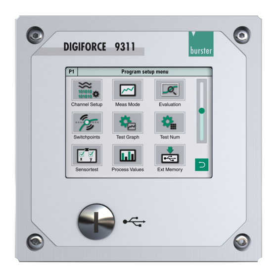
Page 70: Program Setup Menu
Program Setup Menu The "Program Setup Menu" (M78) contains all the settings that relate specifically to measurement programs. You can edit or view the following settings and information in the "Program Setup Menu" (M78): Channel settings Measurement mode Evaluation Graphical test Numerical test Switching points operation... -
Page 71: Channel Settings
6.3.1 Channel settings Note: In the Basic setup menu you can define whether you want the channel settings to apply to all the measurement programs ("globally"), or specifically to each measurement program ("program depending"). Please note that when the "globally" option is set, any change will overwrite the settings for all the measurement programs. -
Page 72: Scaling Analog Sensors (Strain Gage, Potentiometer, Standard Signal Sensors)
Parameters in the "Channel settings" menu (M21) Axis X, Y Active measurement channel, X or Y. You cannot edit this parameter. Socket A, B, t (time) Assign a physical connector to measurement channel X or Y. (Alternatively you can set a time axis here.) Sensor Assign the relevant sensor type: Connector A: potentiometer or standard signal... -
Page 73: Inverting Measurement Signals
TEDS function for the optional piezoelectric input. Note: If when using burster TEDS sensors you wish to invert a signal, you can do this by changing the sign in the scaling values. You must make the change after importing the TEDS data ([Read TEDS]). -
Page 74: Potentiometric Sensors
6.3.1.4 Potentiometric sensors You can connect potentiometric sensors to connector A. Diagram 34: Channel settings for potentiometric sensors - page 1 Parameters in the "X-axis Socket A Potentiometer" menu (M23) – page 1 Excitation voltage Shows the excitation voltage for the potentiometer This value cannot be changed. - Page 75 Diagram 35: Channel settings for potentiometric sensors - page 2 Parameters in the "X-axis Socket A Potentiometer" menu (M23) – page 2 Lower scale <value input> Enter the lower scale value for 2-point scaling (typically = 0). Upper scale <value input> Enter the upper scale value for 2-point scaling (typically 100 % of the sensor measurement range).
- Page 76 Note: The mechanical travel of potentiometric displacement sensors is greater than the specified measurement travel. Therefore an electrical dead zone usually exists at each end. Within this zone, you cannot measure any change in the electrical output signal despite a movement being made.
- Page 77 Make the sensor-specific settings for the potentiometric sensor. Swipe the touchscreen to open the second page. Make further sensor-specific settings for the potentiometric sensor on this page. to return to the "Channel settings" menu. 10 Tap to close the "Channel settings" menu. Note: Before closing the menu you must press [ENTER] to save any changes you have made to the settings, otherwise the settings are lost.
- Page 78 Using user-defined units The "Unit" parameter offers you a choice of physical units. You can also define your own units as an alternative. In measurement mode, tap anywhere on the touchscreen. The icon appears in the bottom-right corner. to open the "Configuration Main Menu". Tap the "Program Setup"...
- Page 79 Tare setup for potentiometric sensors In the menu "X-axis Potentiometer Taring" (M62) you can make additional tare settings for this channel. In measurement mode, tap anywhere on the touchscreen. The icon appears in the bottom-right corner. to open the "Configuration Main Menu". Tap the "Program Setup"...
- Page 80 Enable the checkbox "Tare at meas. start“ and use the keypad to enter the default tare value ("Standard value for tare"). If you enable the "OUT_WARNING_TARE" checkbox, then the "OUT_WARNING_ TARE" control output will be set if the Tare warning limit is exceeded. to return to the menu "X-axis Socket A Potentiometer".
- Page 81 Reading potentiometric sensors programmed with TEDS If a connected sensor is programmed with TEDS, you can use the [Read TEDS data] function to get the ® DIGIFORCE 9311 to upload the sensor specification. The instrument can then use this specification to make the necessary channel settings automatically.
- Page 82 Tap [TEDS Info] to display the data from the potentiometric sensor. Tap [ENTER] to close the display. If the instrument has not detected a potentiometric sensor programmed with TEDS, it displays a window containing the message "No TEDS found". of 216...
-
Page 83: Sensors That Output A Standard Signal
6.3.1.5 Sensors that output a standard signal You can connect standard-signal sensors to connectors A and B. Diagram 36: Channel settings for standard-signal sensors - page 1 ® Note: Please note that the DIGIFORCE 9311 does not provide a supply voltage for active sensors. Parameters in the "X/Y-axis Socket A/B Standard signal"... - Page 84 Diagram 37: Channel settings for standard-signal sensors - page 2 Parameters in the "X/Y-axis Socket A/B Standard signal" menu (M24) – page Lower scale <value input> Enter the lower scale value for 2-point scaling (typically = 0). Upper scale <value input> Enter the upper scale value for 2-point scaling (typically 100 % of the sensor measurement range).
- Page 85 In measurement mode, tap anywhere on the touchscreen. The icon appears in the bottom-right corner. to open the "Configuration Main Menu". Tap the "Program Setup" icon. Tap the "Channel Setup" icon. You can configure each axis independently. Under "Socket", select the relevant connector for the axis concerned.
- Page 86 Swipe the touchscreen to open the second page. Make further sensor-specific settings for the standard-signal sensor on this page. to return to the "Channel settings" menu. 10 Tap to close the "Channel settings" menu. Note: Before closing the menu you must press [ENTER] to save any changes you have made to the settings, otherwise the settings are lost.
- Page 87 Using user-defined units The "Unit" parameter offers you a choice of physical units. You can also define your own units as an alternative. In measurement mode, tap anywhere on the touchscreen. The icon appears in the bottom-right corner. to open the "Configuration Main Menu". Tap the "Program Setup"...
- Page 88 Tare Setup for standard-signal sensors In the menu "X/Y-axis Stand. signal Taring" (M62) you can make additional tare settings for this channel. In measurement mode, tap anywhere on the touchscreen. The icon appears in the bottom-right corner. to open the "Configuration Main Menu". Tap the "Program Setup"...
- Page 89 Enable the checkbox "Tare at meas. start“ and use the keypad to enter the default tare value ("Standard value for tare"). If you enable the "OUT_WARNING_TARE" checkbox, then the "OUT_WARNING_ TARE" control output will be set if the Tare warning limit is exceeded. to return to the menu "X/Y-axis Socket A Stand.
- Page 90 Reading standard-signal sensors programmed with TEDS If a connected sensor is programmed with TEDS, you can use the [Read TEDS data] function to get the ® DIGIFORCE 9311 to upload the sensor specification. The instrument can then use this specification to make the necessary channel settings automatically.
- Page 91 Tap [TEDS Info] to display the data from the standard-signal sensor. Tap [ENTER] to close the display. If the instrument has not detected a standard-signal sensor programmed with TEDS, it displays a window containing the message "No TEDS found". of 216...
-
Page 92: Strain Gage Sensors
6.3.1.6 Strain gage sensors You can connect strain gage sensors to connector B. Diagram 38: Channel settings for strain gage sensors - page 1 Note: A 5 VDC excitation voltage is used for strain gages. Parameters in the "Y-axis Socket B Strain gage" menu (M22) – page 1 Sensitivity 0.02 to 100 mV/V Enter the strain gage sensitivity... - Page 93 Diagram 39: Channel settings for strain gage sensors - page 2 Parameters in the "Y-axis Socket B Strain gage" menu (M22) – page 2 Lower scale <value input> Enter the lower scale value for 2-point scaling (typically = 0). Upper scale <value input>...
- Page 94 In measurement mode, tap anywhere on the touchscreen. The icon appears in the bottom-right corner. to open the "Configuration Main Menu". Tap the "Program Setup" icon. Tap the "Channel Setup" icon. You can configure each axis independently. Under "Socket", select the relevant connector for the axis concerned.
- Page 95 Swipe the touchscreen to open the second page. Make further sensor-specific settings for the strain gage sensor on this page. to return to the "Channel settings" menu. 10 Tap to close the "Channel settings" menu. Note: Before closing the menu you must press [ENTER] to save any changes you have made to the settings, otherwise the settings are lost.
- Page 96 Using user-defined units The "Unit" parameter offers you a choice of physical units. You can also define your own units as an alternative. In measurement mode, tap anywhere on the touchscreen. The icon appears in the bottom-right corner. to open the "Configuration Main Menu". Tap the "Program Setup"...
- Page 97 Tare setup for strain gage sensors In the menu "Y-axis Strain gage Taring" (M62) you can make the extra tare settings for this channel. In measurement mode, tap anywhere on the touchscreen. The icon appears in the bottom-right corner. to open the "Configuration Main Menu". Tap the "Program Setup"...
- Page 98 Enable the checkbox "Tare at meas. start“ and use the keypad to enter the default tare value ("Standard value for tare"). If you enable the "OUT_WARNING_TARE" checkbox, then the "OUT_WARNING_ TARE" control output will be set if the Tare warning limit is exceeded. to return to the menu "Y-axis Socket A Strain gage".
- Page 99 Reading strain gage sensors programmed with TEDS If a connected sensor is programmed with TEDS, you can use the [Read TEDS data] function to get the ® DIGIFORCE 9311 to upload the sensor specification. The instrument can then use this specification to make the necessary channel settings automatically.
- Page 100 If the instrument detects a strain gage sensor programmed with TEDS, it displays the [TEDS Info] button. Note: Once it has read the TEDS data, the instrument overwrites the relevant parameters such as the scaling and calibration values. These parameters can be post- edited, for instance to set signal inversion.
-
Page 101: Piezoelectric Sensors (Option)
6.3.1.7 Piezoelectric sensors (option) You can connect piezoelectric sensors (with a charge output) only to the optional piezoelectric input (connector B). ® Note: For this function your DIGIFORCE 9311 must be fitted with the optional piezoelectric input. With this option, connector B for a strain-gage or standard-signal input is no longer provided. ®... - Page 102 Diagram 41: Channel settings for piezoelectric sensors - page 2 Parameters in the "Y-axis Socket B Piezo" menu (M25) – page 2 Lower scale <value input> Enter the lower scale value for 2-point scaling (typically = 0). Upper scale <value input> Enter the upper scale value for 2-point scaling (typically this is 100% of the sensor measurement range, or can be set as a multiple of 1, because the...
- Page 103 In measurement mode, tap anywhere on the touchscreen. The icon appears in the bottom-right corner. to open the "Configuration Main Menu". Tap the "Program Setup" icon. Tap the "Channel Setup" icon. You can configure each axis independently. Under "Socket", select the relevant connector for the axis concerned.
- Page 104 Swipe the touchscreen to open the second page. Make further sensor-specific settings for the piezoelectric sensor on this page. to return to the "Channel settings" menu. 10 Tap to close the "Channel settings" menu. Note: Before closing the menu you must press [ENTER] to save any changes you have made to the settings, otherwise the settings are lost.
- Page 105 Using user-defined units The "Unit" parameter offers you a choice of physical units. You can also define your own units as an alternative. In measurement mode, tap anywhere on the touchscreen. The icon appears in the bottom-right corner. to open the "Configuration Main Menu". Tap the "Program Setup"...
-
Page 106: Measurement Mode
6.3.2 Measurement mode In the "Measurement mode" menu (M19) you can specify the signal acquisition parameters for the measurement phase. Essentially the parameters you need to set are the signal sampling, the X-reference for the measurement curve, the curve segment (just the forward curve or the entire measurement curve) and the start/stop condition for the measurement phase. -
Page 107: Sampling The Measurement Channels
6.3.2.1 Sampling the measurement channels ® The DIGIFORCE 9311 lets you sample signals using a combination of time interval (Δt), X-interval and Y-interval (ΔX, ΔY). This provides flexibility while also letting you compress the measurement recording. It means that you can use just a few measurement points to record curve regions containing a constant or steadily changing signal, whereas you can use more points when you need to record and reproduce steep signal slopes or alternating waveforms. - Page 108 Absolute reference By selecting the "Absolute" setting you are setting the X-axis reference of the measurement curve to the zero point of the currently connected sensor. You can choose the "Absolute" reference option when you are able to position both parts involved in a joining process with repeat precision, i.e.
- Page 109 Final force reference ® With the "Final force" reference (final force used as the reference), the DIGIFORCE 9311 shifts the curve to after the measurement phase and references it to the X-value of the last measurement point ® (final force). If a measurement curve contains a forward and return section, the DIGIFORCE 9311 sets the return point as zero when the reference is set to "Final force".
- Page 110 Parameters in the "Measurement mode, Final force reference" menu (M19) Reference Final force The last measurement point of the forward measurement curve is the reference point (X = 0). For a forward and return curve, the return point is the reference.
- Page 111 Reference: crossing Y trigger threshold Unlike the "Absolute", "Final force" and "Reference line" references, when the "Trigger" reference is used, recording of the measurement does not start until the measurement crosses the configured threshold ® (e.g. force threshold). The DIGIFORCE 9311 writes the value pairs of the measurement curve from this ®...
-
Page 112: Curve Recording, Return Point
6.3.2.3 Curve recording, return point ® The DIGIFORCE 9311 divides a recorded measurement curve into two curve segments: a forward segment and a return segment. You can use the "Record curve to" parameter to select between "Complete curve" and "Return point". Select "Complete curve"... -
Page 113: Start/Stop Mode
Example 2 Record curve to: Return point Return point: Xmax Diagram 50: Example 2: record the curve up to the return point Xmax 6.3.2.4 Start/Stop mode ® The DIGIFORCE 9311 lets you set separate start/stop conditions for recording a measurement curve. Apart from the routine practice of using an external control signal, you can also start or stop a measurement when a sensor signal crosses a defined threshold. - Page 114 specified time has elapsed. Number of readings: The measurement is stopped once the specified number of measurement-value pairs has been recorded. X / Y stop value; ---- / <value input> Set here the stop-condition threshold if an internal stop mode is selected. Alternatively, if "No.of Number of readings"...
-
Page 115: Configuring The Evaluation
6.3.3 Configuring the evaluation You have two ways of activating and configuring graphical evaluation elements on the ® DIGIFORCE 9311. In the "Select evaluation elements" menu (M10), you can select and enable the graphical evaluation elements and also set their numerical values. This menu, however, does not let you visualize directly how the graphical evaluation element appears and is positioned in the X/Y graph. - Page 116 Symbol Description Window without entry or exit; measurement curve lies entirely inside the window. Window without entry or exit; measurement curve lies entirely outside the window (NOT window). The "Window" graphical evaluation element outputs the following results data: Individual evaluation ®...
- Page 117 Absolute maximum Symbol Window evaluation element ® The DIGIFORCE 9311 determines the absolute maximum of the Y-value between entry and exit points as an X/Y value pair. ® The DIGIFORCE 9311 only considers curve points inside the window when finding this value. Absolute minimum Symbol Window evaluation element...
- Page 118 If required, enable "Online evaluation". You can only enable this option for one window. You are then offered the choice of "Off", "Left > Right", "Right > Left", "Bottom > Top" and "Top > Bottom". Confirm your selection with [ENTER]. ®...
- Page 119 Parameters in the "Window configuration" menu (M16) Window number 1 to 3 Choice of window 1, 2 or 3 Window On / Off Enable/disable Curve segment Forward, Return, Specify the curve segment for which the window Complete curve is active. Online evaluation With Online evaluation enabled, the associated online signal goes to active level immediately it...
-
Page 120: Trapezoid
6.3.3.2 Trapezoid You can set the "Trapezoid" graphical evaluation element to be of type "Trapezoid X" or "Trapezoid Y". The "Trapezoid X" type is specified by fixed vertical X-limits (Xmin, Xmax) and the "Trapezoid Y" type by fixed horizontal Y-limits (Ymin, Ymax). You can configure up to two trapezoids in one measurement ®... - Page 121 Entry Symbol Trapezoid evaluation element ® The DIGIFORCE 9311 linearly interpolates the trapezoid entry coordinates from the last measurement point outside the trapezoid and the first measurement point inside the trapezoid. If the measurement curve starts inside the trapezoid area, the ®...
- Page 122 Tap "Curve segment" to define the curve segment for which the trapezoid is active. You can choose "Forward", "Return" or "Complete curve". Confirm your selection with [ENTER]. 10 Swipe the touchscreen to open the second page. 11 If you have selected a trapezoid of type "Trapezoid X", tap the fields [YmaxLe], [YminLe], [YmaxRi], [YminRi], [Xmin] and [Xmax] and in each case use the keypad to...
- Page 123 Parameters in the "Trapezoid window configuration" menu (M13) Number 1 or 2 Choice of trapezoid window 1 or 2 Window On / Off Enable/disable Type Trapezoid X, Trapezoid Y Select the trapezoid type Curve segment Forward, Return, Complete Specify the curve segment for which the curve trapezoid window is active.
-
Page 124: Threshold
Exit Bottom, Top Side at which the curve exits the Y trapezoid Possible options: • one exit side • more than one exit side • no exit 6.3.3.3 Threshold The "Threshold" graphical evaluation element can be used to calculate and monitor the point at which the ®... - Page 125 Configuring a threshold In measurement mode, tap anywhere on the touchscreen. The icon appears in the bottom-right corner. to open the "Configuration Main Menu". Tap the "Program Setup" icon. Tap the "Evaluation" icon. Tap the "Threshold" icon. Tap "Threshold" and enter your required threshold number (1 or 2) via the keypad. You can configure up to two thresholds.
- Page 126 13 If you have selected a "Type Y threshold", tap the fields [Y], [Xmin] and [Xmax] and in each case use the keypad to enter the coordinates to specify the position and size of the threshold. 14 Tap to set the relevant direction for the entry/exit side of the threshold. Note: For the "Y threshold"...
- Page 127 Parameters in the "Threshold configuration" menu (M14) Threshold number 1 to 2 Choice of threshold 1 or 2 Threshold On / Off Enable/disable Threshold type X threshold Select whether the threshold is type X or type Y Y threshold Curve segment Forward, Return, Complete Specify the curve segment for which the curve...
-
Page 128: Envelopes
6.3.3.4 Envelopes ® The DIGIFORCE 9311 can generate from one or more measurement curves an "envelope" for each measurement program. You can generate an "Envelope" only in the "Graphical test operation" menu (M59), where you use at least one existing measurement curve as the basis for the envelope (see section 6.3.5.6 "Graphical Test Operation –... - Page 129 Parameters in the menu "Envelope X[mm] Y[N]" (M11) Envelope On / Off Enable/disable Entry Left, Right, Top, Bottom Specify the direction in which the curve passes through the envelope Curve segment Forward, Return Specify the curve segment for which the envelope is active.
-
Page 130: Tolerance Band For Evaluation Elements
6.3.3.5 Tolerance band for evaluation elements You can use the tolerance band for graphical evaluation elements to configure an additional hysteresis region at the boundaries of the element, so for instance at the entry and exit side of a window. In this hysteresis band, the measurement curve can cross back and forth across the boundary line of the graphical evaluation element any number of times without resulting in an NOK evaluation. - Page 131 Parameters in the "Tolerance band" menu (M72) Tolerance band X <value input> Define the hysteresis band in the X-axis direction Tolerance band Y <value input> Define the hysteresis band in the Y-axis direction of 216...
-
Page 132: Online Switching Points
6.3.4 Online switching points WARNING NOT a substitute for safety devices and protective equipment The online switching signals S1 to S6 are NOT a substitute for safety devices and protective equipment. Use safety devices and protective equipment. Note: The switching signals S1 to S6 do not meet the requirements for a safety switch. It is the responsibility of the owner of the complete system, such as a press, to equip the system with the required safety devices and protective equipment. - Page 133 Parameters in the menu "Setup realtime switchpoints S1 to S6" (menu 12) Value Limit threshold Enter the limit threshold Units Units display Displays the units for the measurement channel Channel X, Y Select the active measurement channel for the respective switching signals S1 to S6 Active High / Low Select whether signal is active high or active...
-
Page 134: Graphical Test Operation
6.3.5 Graphical test operation In the "Graphical test operation" menu (M59) you can perform measurements in one or more measurement programs and use the recorded measurement curve(s) to define the graphical evaluation elements such as "Window", "Trapezoid", "Threshold" and "Envelope". The 10 most recent measurement results from each measurement program are saved. - Page 135 In measurement mode, tap anywhere on the touchscreen. The icon appears in the bottom-right corner. to open the "Configuration Main Menu". Tap the "Program Setup" icon. Tap the "Graph. TestOp." icon. to return to the "Program Setup" menu. Graphical test operation – Main dialog window Diagram 58: Graphical test operation –...
-
Page 136: Graphical Test Operation - Zoom (Adjust Zoom For X/Y Graphs)
6.3.5.1 Graphical Test Operation - Zoom (adjust zoom for X/Y graphs) You can set the zoom (scale) for the X/Y-axes of the measurement curve graph in the "Graphical test operation" menu (M59), with a choice of "Auto" or "FixScale" zoom modes. In "Auto" mode, the axes are scaled so that the entire measurement curve is visible including all the active graphical evaluation elements such as "Window", "Trapezoid", "Threshold"... - Page 137 Note: If "Auto" zoom mode is enabled, then any region that you have selected for magnification is reset when you close the "Graphical test operation" menu (M59). Tapping AutoSize will redisplay the entire measurement curve including all the active evaluation elements.
-
Page 138: Graphical Test Operation - Autoset
Tap AutoSize to display the entire measurement curve including all the graphical evaluation elements. to return to the "Graphical test operation" menu. 6.3.5.2 Graphical test operation – AutoSet Once you have recorded a measurement curve in measurement mode or in the "Graphical test operation" ®... - Page 139 In measurement mode, tap anywhere on the touchscreen. The icon appears in the bottom-right corner. to open the "Configuration Main Menu". Tap the "Program Setup" icon. Tap the "Graph. TestOp." icon. Tap [Evaluation]. Tap [AutoSet]. This opens the "Window configuration" menu for Window 1. Note: The [AutoSet] function disables all the active graphical evaluation...
-
Page 140: Graphical Test Operation - Configuring A Window
6.3.5.3 Graphical Test Operation – Configuring a window In the "Graphical test operation" menu (M59) you can enable the "Window" graphical evaluation element and place it, move it and change its size directly in the measurement curve graph. To access the full set of parameters, you can switch to the "Window configuration"... - Page 141 In measurement mode, tap anywhere on the touchscreen. The icon appears in the bottom-right corner. to open the "Configuration Main Menu". Tap the "Program Setup" icon. Tap the "Graph. TestOp." icon. Tap [Evaluation]. Tap [Window] and select your required window number (1 to 3). Tap [Off] to activate the window.
- Page 142 Configuring a window - Numerical Tap [Numerical] to open the "Window configuration" menu (M16) for the previously selected window. For details of the possible settings, please refer to section 6.3.3.1 "Window" on page 115. Configuring a window - Limits If you tap [Limits], you can change the position and size of the selected window directly on the touchscreen using your finger.
- Page 143 Place your finger in the centre of the window and drag it in the direction in which you want to move the window. Place your finger on one of the corners and drag it across the touchscreen to change the limits.
- Page 144 In "Graphical test operation / Window 1 to 3" tap [AutoSize] to adjust the size of the window. Tap [Numerical] to open the "Window configuration" menu and then set the correct "Curve segment". You have a choice of "Forward", "Return" or "Complete curve". to return to the "Graphical test operation / Window 1 to 3"...
-
Page 145: Graphical Test Operation - Configuring A Trapezoid
6.3.5.4 Graphical Test Operation – Configuring a trapezoid In the "Graphical test operation" menu (M59) you can enable the "Trapezoid" graphical evaluation element and place it, move it and change its size directly in the measurement curve graph. To access the full set of parameters, you can switch to the "Trapezoid window configuration"... - Page 146 In measurement mode, tap anywhere on the touchscreen. The icon appears in the bottom-right corner. to open the "Configuration Main Menu". Tap the "Program Setup" icon. Tap the "Graph. TestOp." icon. Tap [Evaluation]. Tap [Trapez.] and select your required trapezoid number (1 or 2). Tap [Off] to activate the trapezoid.
- Page 147 Configuring a trapezoid - Numerical Tap [Numerical] to open the "Trapezoid window configuration" menu (M13) for the previously selected trapezoid. For details of the possible settings, please refer to section 6.3.3.2 “Trapezoid” on page 120. Select here whether you want to use a "Trapezoid X" or "Trapezoid Y" as the trapezoid type. Configuring a trapezoid - Limits If you tap [Limits], you can change the position and size of the selected trapezoid directly on the touchscreen using your finger.
- Page 148 Place your finger in the centre of the trapezoid and drag it in the direction in which you want to move the trapezoid. Place your finger on one of the corners and drag it across the touchscreen to change the limits.
- Page 149 In "Graphical test operation / Trapez. 1 or 2" tap [AutoSize] to adjust the size of the trapezoid. Tap [Numerical] to open the "Trapezoid window configuration" menu and then set the correct "Curve segment". You have a choice of "Forward", "Return" or "Complete curve". to return to the "Graphical test operation / Trapez.
-
Page 150: Graphical Test Operation - Configuring A Threshold
6.3.5.5 Graphical Test Operation – Configuring a threshold In the "Graphical test operation" menu (M59) you can enable the "Threshold" graphical evaluation element and place it, move it and change its size directly in the measurement curve graph. To access the full set of parameters, you can switch to the "Threshold configuration"... - Page 151 In measurement mode, tap anywhere on the touchscreen. The icon appears in the bottom-right corner. to open the "Configuration Main Menu". Tap the "Program Setup" icon. Tap the "Graph. TestOp." icon. Tap [Evaluation]. Tap [Thresh.] and select your required threshold number (1 or 2). Tap [Off] to activate the threshold.
- Page 152 Configuring a threshold - Numerical Tap [Numerical] to open the "Threshold configuration" menu (M14) for the previously selected threshold. For details of the possible settings, please refer to section 6.3.3.3 "Threshold" on page 124. Note: Select here, amongst other settings, whether you want to use an "X threshold" or "Y threshold" as the threshold type.
- Page 153 Place your finger in the centre of the threshold and drag it in the direction in which you want to move the threshold. Place your finger on one of the corners and drag it across the touchscreen to change the limits.
- Page 154 Tap [AutoSize] in the "Graphical test operation / Thresh. 1 or 2" menu to adjust the size of the threshold. Tap [Numerical] to open the "Threshold configuration" menu and then set the correct "Curve segment". You have a choice of "Forward", "Return"...
-
Page 155: Graphical Test Operation - Generating An Envelope
6.3.5.6 Graphical Test Operation – Generating an envelope In the "Graphical test operation" menu (M59) you can generate the "Envelope" graphical evaluation element. To do this, you need to run at least one measurement. When generating the envelope, all the measurements available in the curve memory (up to 10 measurement curves) are used as the basis for the calculation. - Page 156 Tap [Envelope]. Tap [Off] to activate the envelope. Note: You must run at least one measurement before you can generate the envelope. All the measurement curves stored in the curve array memory are used as the basis for calculating the envelope.
- Page 157 ® Note: The DIGIFORCE 9311 can only generate an "envelope" if the entire curve segment (forward or return) runs in a continuous direction i.e. for a left or right entry, only one Y-value must be associated with each X-coordinate, or for a bottom or top entry, only one X-value must be associated with each Y-coordinate.
- Page 158 Tap [Limits] in the "Graphical test operation / Envelope" menu. Place your finger on the left-hand or right- hand point and drag it in the appropriate direction to enlarge or reduce the X-range of the envelope. Note: After the envelope is generated, the entry/exit sides lie at the maximum possible values, i.e.
-
Page 159: Graphical Test Operation - Cursor
6.3.5.7 Graphical test operation – Cursor You can use the [Cursor] in the "Graphical test operation / Cursor" menu (M59) to select any measurement-value pair and read off the associated X/Y values. Diagram 70: Graphical test operation – Cursor In measurement mode, tap anywhere on the touchscreen. The icon appears in the bottom-right corner. - Page 160 Place your finger on the yellow line and drag it to right or left across the touchscreen to select the measurement-value pair you require. You can also tap [>>] or [<<] to move the cursor left or right. to return to the "Graphical test operation" menu. Note: The "Cursor"...
-
Page 161: Graphical Test Operation - Reference Curve
6.3.5.8 Graphical test operation – Reference curve You can use [Ref-Curve] in the "Graphical test operation" menu (M59) to save the current measurement curve as the reference curve and display this curve in the graph in measurement mode. The reference curve is shown in violet and can be used by an operator to identify any differences between the actual curve and ideal curve. - Page 162 A window opens displaying the message "Ref-Curve saved!". Tap [ENTER] to confirm the save. The reference curve is now shown in violet. to return to the "Graphical test operation" menu. of 216...
-
Page 163: Graphical Test Operation - Displaying A Curve Array
6.3.5.9 Graphical Test Operation – Displaying a curve array You can use [CrvArray] in the "Graphical test operation" menu (M59) to display simultaneously the 10 most recent measurement curves as a curve array. This lets you easily and conveniently identify any ®... - Page 164 The selected measurement curve is shown in violet. You can use [>>] or [<<] to select a different measurement curve, or [Delete] to remove a curve from the curve array. to return to the "Graphical test operation" menu. of 216...
-
Page 165: Numerical Test Operation
6.3.6 Numerical test operation In the "Numerical test operation" menu (M58) you can retrieve the live sensor values from the active measurement channels X and Y and retrieve the status of the PLC control signals (inputs and outputs). You can also tare each measurement channel separately (the tare function is not available for the optional piezoelectric input). -
Page 166: Numerical Test Operation - Live Sensor Values
6.3.6.1 Numerical Test Operation - Live sensor values In the "Numerical test operation" menu (M58), you can view the live sensor values. For analog sensor signals such as strain gage, potentiometer or standard signals, you can set the resolution for the reading to either a four-digit or five-digit display. - Page 167 Tap anywhere in the header of the "Numerical test operation" menu. Tap the resolution you require and confirm your selection with [ENTER]. You have a choice of "normal" or "high". to return to the "Program Setup" menu. of 216...
-
Page 168: Numerical Test Operation - Tare
6.3.6.2 Numerical Test Operation – Tare You can use the [Tare X] and [Tare Y] buttons to tare the live sensor values. Running the tare function will zero the live sensor value or set it to a configurable default value ("Standard value for tare") (for details see the relevant subsection for the individual sensors in section 6.3.1 "Channel settings"... -
Page 169: Numerical Test Operation - Plc Signals
6.3.6.3 Numerical Test Operation - PLC signals You can retrieve the live states of the PLC inputs and outputs in the "Numerical test operation" menu (M58), and also set/reset the PLC outputs. You can also use this function when the instrument is controlled via the Fieldbus option (e.g. - Page 170 Tap [Set!] or [Reset!] to change the state of the PLC output. Tap [<<] or [>>] to select the PLC input you require. to return to the "Program Setup" menu. Online switching points If a measurement exceeds the set limit level then the associated online switching point (S1 to S6) responds in the "Numerical test operation"...
-
Page 171: Sensor Test
6.3.7 Sensor test The "Sensor test" function can be used for cyclical testing of the active measurement channels. In the ® test, the DIGIFORCE 9311 compares the live measurements with stored reference values. The ® DIGIFORCE 9311 evaluates the result as "sensor test OK/NOK" depending on whether or not the measured value lies within the defined tolerance;... - Page 172 Parameters for channels X and Y in the "Sensor test" menu (M35) Sensor test On / Off Enable/disable Measured setpoint <value> Reference value measured for the sensor test. This value is used as the comparison value when running the sensor test. If the value measured during the sensor test lies within the permitted tolerance, the control signal "OUT_OK_STEST"...
-
Page 173: User-Defined Values
6.3.8 User-defined values ® The DIGIFORCE 9311 can display a range of results in measurement mode, which you can also output via an interface, for instance the PLC interface (please see section 7.6 "M5 User defined values" on page 192). These measurement results include, for instance, entry and exit values for the graphical evaluation ®... - Page 174 Pos Xmax Window boundary, Xmax 1/2/3 Pos Ymin Window boundary, Ymin 1/2/3 Pos Ymax Window boundary, Ymax 1/2/3 Trapezoid (1 or 2) Entry X Trapezoid entry value – X-coordinate Entry Y Trapezoid entry value – Y-coordinate Exit X Trapezoid exit value – X-coordinate Exit Y Trapezoid exit value –...
- Page 175 Type Y threshold Pos Threshold Y-position of threshold Pos Xmin Limit of threshold, Xmin Pos Xmax Limit of threshold, Xmax Envelope EN Entry X Envelope entry value – X-coordinate EN Entry Y Envelope entry value – Y-coordinate EN Exit X Envelope exit value –...
-
Page 176: Usb Flash
6.3.9 USB flash In the "USB flash" menu (M80), you can enable/disable data logging on an external USB stick. Note: If you wish to log the measurement data on the USB stick, you need to individually enable data logging for each measurement program. Plug a USB stick into the rear USB port. -
Page 177: Copy Programs
Copy programs In the "Copy programs" menu (M38), you can copy measurement programs and sensor settings or initialize programs with a set of initial settings. Copying a measurement program or sensor settings 6.4.1 If you want to re-use most of the settings in a measurement program, you can make a copy of the measurement program. - Page 178 You have a choice of two different copy options: [Copy channel settings] and [Copy whole setup]. [Copy channel settings] overwrites just the sensor channel settings. [Copy whole setup] overwrites all the settings in the measurement program. Note: The [Copy channel settings] function is not available if the channel settings in the "Basic setup"...
-
Page 179: Deleting A Measurement Program
6.4.2 Deleting a measurement program If you want to discard all the settings for one or more measurement programs, you can do this using ® [Initialize target program(s)]. The DIGIFORCE 9311 then resets the relevant measurement programs to the factory settings. This cannot be undone. The settings of the selected measurement programs are lost. -
Page 180: Curve Analysis (Viewer)
Curve analysis (Viewer) You can use the “Graphical Curve analysis” menu (M70) to look at the most recent 50 measurement curves either as individual curves or as a curve array. In addition, you have detailed numeric data available for each measurement, for instance individual results from the graphical evaluation elements and the associated measured values such as "Window"... - Page 181 In measurement mode, tap anywhere on the touchscreen. The icon appears in the bottom-right corner. to open the "Configuration Main Menu". Tap the "Curve Analysis" icon. Tap [Single] or [Curve arr] to display a single measurement curve or a set of curves (curve array).
-
Page 182: Curve Analysis - Selection
6.5.1 Curve analysis - Selection In the “Graphical Curve analysis” menu (M70) you can tap [Selection] to choose the individual measurement curves to be displayed as a curve array. In measurement mode, tap anywhere on the touchscreen. The icon appears in the bottom-right corner. -
Page 183: Curve Analysis - Zoom
6.5.2 Curve analysis - Zoom In the “Graphical Curve analysis” menu (M70) you can use [Zoom] to adjust the scale of the X/Y graph. You can use the magnifying glass as a particularly easy way to select a region of the graph that you want to magnify. -
Page 184: Curve Analysis - Numerical
6.5.3 Curve analysis - Numerical In the “Graphical Curve analysis” menu (M70) you can use the [Numerical] option to open details of the saved measurements. Tapping the area in the centre ([Time] and [Date]) will display the "General curve data" dataset for the measurement. In the area underneath, you can call up the entry and exit coordinates for the graphical evaluation elements. - Page 185 Tap a field to display the entry and exit coordinates for the graphical evaluation element concerned. Swipe the touchscreen to scroll through the available measurements. to return to the "Graphical Curve analysis" menu. Note: If you have made changes to the instrument configuration after the measurement, this menu displays the following message: "Setup has been changed!".
-
Page 186: Measurement Results Display - Measurement Mode
Measurement results display - Measurement mode Note: In the "Basic setup" menu (M18), you can change the function-key assignments and the display preferences for each of the measurement menus. ® The DIGIFORCE 9311 starts automatically in measurement mode at power-up. In this operating mode, ®... -
Page 187: Global Header
7.1.1 Global header Diagram 79: Global header 7.1.2 Status/error indicator in measurement mode ® S:Ready(<value>) The DIGIFORCE 9311 is ready to perform a measurement (PLC signal: "READY=1"); The value in brackets shows the number of measurement value pairs from the last measurement. S:Ready (>>5000) means that the number of measurement-value pairs in the last measurement has exceeded the maximum permitted value. -
Page 188: Overall Result Of Last Measurement
7.1.3 Overall result of last measurement Display Meaning Measurement OK: every active evaluation element enabled for evaluation has been evaluated as OK. Measurement NOK: at least one active evaluation element enabled for evaluation has been evaluated as NOK. Measurement in progress 7.1.4 Individual evaluation status in measurement mode ®... -
Page 189: M1 Graphical Measurement Curve
M1 Graphical measurement curve The measurement curve plotted on an X/Y graph is displayed in the "M1 Graphical measurement curve" measurement menu. Arrows on the evaluation elements show the required entry/exit points and the crossing direction. Diagram 81: M1 Graphical measurement curve Setting the scale for the X/Y axes (zoom) You can set the scale for the axes in the "Graphical test operation"... -
Page 190: M2 General Curve Data
M2 General curve data The "M2 General curve data" measurement menu displays coordinate pairs (X/Y value pairs) from the "General curve data" results dataset. Diagram 82: M2 General curve data Definition of values in the "General curve data" results Xmin X/Y value pair at X-minimum Xmax X/Y value pair at X-maximum... -
Page 191: M3 Total Result
M3 Total result The "M3 Total result" measurement menu lets you display the evaluation result as a global Pass/Fail result (OK/NOK evaluation). You can opt to display the result as the text Pass/Fail or as a happy/sad smiley. You can also add an acknowledgement function to the overall result page, which prompts for confirmation by the operator (for further details, please see section 6.1.11 "Acknowledgement function"... -
Page 192: M4 Entry/Exit
M4 Entry/Exit The "M4 entry/exit" measurement menu displays the entry and exit coordinates for the active graphical evaluation element. Diagram 85: M4 Entry/Exit M5 User defined values The "M5 User defined values" measurement menu can display up to 20 separate measurement values and results. -
Page 193: M6 Statistics
M6 Statistics The "M6 Statistics" measurement menu shows the percentage of failed parts (NOK evaluations) out of the total number of parts. It also shows the NOK percentage for each active graphical evaluation element with respect to the total number of NOK evaluations. This display can help you quickly deduce the cause of any NOK measurements. -
Page 194: M7 Order Sheet
M7 Order sheet The "M7 Order sheet" measurement menu is not used for displaying specific measurement data or results. It is a "data container" via which you can transfer administrative or component-specific information for data-logging purposes. You can edit the order sheet manually in the "Order sheet" menu (M52) (for details, please see section 6.1.12 "Order sheet"... -
Page 195: Signal Timing Diagrams
Signal timing diagrams Selecting a measurement program 8.1.1 Changing the measurement program without program acknowledgement Diagram 89: Changing the measurement program without program acknowledgement Cycle a. The controller applies the required program number (binary encoded) to the address ® inputs and checks whether the DIGIFORCE 9311 is ready ("OUT_READY"... -
Page 196: Changing The Measurement Program With Program Acknowledgement
8.1.2 Changing the measurement program with program acknowledgement Diagram 90: Changing the measurement program with program acknowledgement *You can define a configurable PLC output for the signals "OUT_PROG[3...0]". Cycle a. The controller applies the required program number (binary encoded) to the address ®... -
Page 197: Starting A Measurement
Starting a measurement Instead of using external signals, you can also use separate internal events to start and stop a ® measurement in the DIGIFORCE 9311. You define the necessary settings for this in the Measurement mode configuration menu; for details, please see section 6.3.2.4 "Start/Stop mode" on page 113. 8.2.1 Measurement without measurement-data logging Standard measurement cycle without active logging of measurement data via the communication interfaces (Ethernet, USB). -
Page 198: Measurement With Measurement-Data Logging
8.2.2 Measurement with measurement-data logging ® The DigiControl PLUS PC software for the DIGIFORCE 9311 provides the option for automatic data logging at the end of a measurement. When data logging is enabled, the "OUT_READY" signal, which indicates that the instrument is in standby and ready to perform another measurement, is not set until data transmission is complete. -
Page 199: Measurement Using Data Logging On Usb Stick (Ready Control Enabled)
8.2.3 Measurement using data logging on USB stick (READY control enabled) When data logging on a USB stick is active, for each measurement a data entry is made on the USB stick ® plugged into the rear of the DIGIFORCE 9311 (please see section 6.1.13 "USB flash"... -
Page 200: External Tare
External tare 8.3.1 Without tare warning Standard cycle without monitoring of the tare warning limit using measurement channel "Y1" as an example. Diagram 94: Without tare warning Cycle a. The PLC first checks whether the instrument is ready, i.e. if "OUT_READY" = 1. b. -
Page 201: With Tare Warning
8.3.2 With tare warning ® The DIGIFORCE 9311 can generate a warning if the sensor signal to be tared exceeds a configurable threshold value. You can enable and set this threshold in the "Channel settings" menu (M21) (for further details, please see section 6.3.1 "Channel settings" on page 71). Diagram 95: With tare warning *You can define a configurable PLC output for the signal "OUT_WARNING_TARE". -
Page 202: Online Signals
Online signals 8.4.1 Window evaluation with online signal ® For the "Window" evaluation element you can specify that the DIGIFORCE 9311 enables the "OUT_NOK_ONL" online signal if a window evaluation criterion is infringed. This function is often used to monitor the initial-contact region of press-fit processes. If the curve exits the window incorrectly, for instance because misalignment of the parts to be joined ®... -
Page 203: Online Switching Signals S1 To S6
8.4.2 Online switching signals S1 to S6 ® The DIGIFORCE 9311 can enable the switching signals S1 to S6 in measurement mode and in test operation if a measurement exceeds a set value. WARNING NOT a substitute for safety devices and protective equipment The online switching signals S1 to S6 are NOT a substitute for safety devices and protective equipment. -
Page 204: Switching Signals For X-Channel With "Trigger" Reference
8.4.2.2 Switching signals for X-channel with "Trigger" reference ® The DIGIFORCE 9311 can only set/reset the X-channel switching signal with trigger reference during an active measurement, i.e. after the trigger event. The reference for the X-channel is the trigger event, for instance this may be the contact force of a press ram on a component. -
Page 205: Switching Signals For Y-Channel
8.4.2.3 Switching signals for Y-channel ® The DIGIFORCE 9311 sets a Y-channel switching signal when the reading on the Y-channel exceeds ® the specified Y-channel value. If the reading falls below the set value, the DIGIFORCE 9311 resets the signal back to its default status. The signal can be set/reset in measurement mode when the instrument is in standby (ready to measure) and during an active measurement. -
Page 206: Acknowledgement Function
Acknowledgement function ® You can use the DIGIFORCE 9311 Acknowledgement function to control indicator lights and a buzzer ® directly for visual and acoustic signalling of the OK/NOK evaluation. The DIGIFORCE 9311 can also handle an acknowledge input for OK/NOK components where this is required. This acknowledgement function is linked to the "OUT_ACK_LOCK"... -
Page 207: Example Of An Nok Evaluation (Without Acknowledgement)
8.5.2 Example of an NOK evaluation (without acknowledgement) Configuration Acknowledgement function Acknowledge OK-parts Acknowledge NOK-parts Diagram 101: Example of an NOK evaluation (without acknowledgement) *You can define a configurable PLC output for the signals "OUT_ACK_OK" and "OUT_ACK_NOK". of 216... -
Page 208: Example Of An Ok Evaluation (Without Acknowledgement)
8.5.3 Example of an OK evaluation (without acknowledgement) Configuration Acknowledgement function Acknowledge OK-parts Acknowledge NOK-parts Diagram 102: Example of an OK evaluation (without acknowledgement) *You can define a configurable PLC output for the signals "OUT_ACK_OK" and "OUT_ACK_NOK". Note: The buzzer is active here until the start of the next measurement. of 216... -
Page 209: External Actuation Of A Statistics Reset
External actuation of a statistics reset You can use the "IN_RESET" control signal to reset the part counter and NOK counter and also the ® evaluation element statistics. The DIGIFORCE 9311 resets the statistics for all the measurement programs in this case. The following values are reset by this function: •... -
Page 210: External Actuation Of A Sensor Test
External actuation of a sensor test ® You can use the "IN_STEST" signal to run the "sensor test" configured in the DIGIFORCE 9311. In this test, you can check the sensor signals from measurement channels X and Y against a stored value including any tolerance that has been set. -
Page 211: Customer Services For Your Digiforce ® 9311
To inquire about our customer services for your DIGIFORCE 9311, please telephone our Service department on +49 7224 645-53, or email: service@burster.com (Germany only). If you are outside Germany, you should contact your burster agent (see also www.burster.com). of 216... -
Page 212: Technical Data
Technical data Please refer to the data sheet for the technical specification. You can obtain the latest data sheet and ® additional information on the DIGIFORCE 9311 from http://goo.gl/muUe7D or simply use the QR code below: 10.1 Electromagnetic compatibility 10.1.1 Interference immunity Interference immunity in compliance with EN 61326-1:2013 Industrial environment 10.1.2 Interference emission... -
Page 213: Accessories Available
Accessories available Please refer to the data sheet for details of the accessories available. You can obtain the latest data ® sheet and additional information on the DIGIFORCE 9311 from http://goo.gl/muUe7D or simply use the QR code below: 11.1 Software The data sheet contains details of the various versions of the DigiControl PC software. -
Page 214: Disposal
Disposal Battery disposal In Germany, the end user is legally obliged to return all used batteries, and it is illegal to dispose of batteries in the household waste. This law may also affect you as purchaser of the instrument described here. Please dispose of your used batteries properly and in accordance with national statutory regulations. -
Page 215: Index
Index Function keys · 10, 23, 44, 45, 56, 172, 186 " "Absolute" · 19 "Window" · 202 General curve data · 173, 174 "Window“ · 29, 115, 116, 117, 120, 134, 136, 138, Global header · 186 140, 180 Graphical evaluation elements ·... - Page 216 PLC outputs · 28, 29, 43, 46, 56, 119, 165, 169, 170, Potentiometer · 17, 30, 72, 74, 75, 76, 78, 79, 80, 166 Tare · 44, 74, 79, 80, 83, 88, 89, 92, 97, 98, 134, 168, Potentiometric sensors · 31, 74, 81 172, 200, 201 PROFIBUS ·...
Need help?
Do you have a question about the DIGIFORCE 9311 and is the answer not in the manual?
Questions and answers