Burster DIGIFORCE 9307 Operation Manual
Instrument for monitoring repetitive production processes
Hide thumbs
Also See for DIGIFORCE 9307:
- Operation manual (503 pages) ,
- Operation manuals (175 pages) ,
- Operation manual (205 pages)
Table of Contents
Advertisement
Quick Links
Download this manual
See also:
Operating Manual
© 2016
burster
praezisionsmesstechnik gmbh & co kg
All rights reserved
Valid from:
01.06.2016
Revision A
DIGIFORCE
Applies to:
PROFINET firmware version
PN-V16.1.0 required
OPERATION MANUAL
DIGIFORCE
PROFINET manual
®
9307-V0X03
®
9307
Manufacturer:
burster
praezisionsmesstechnik gmbh & co kg
Talstraße 1 - 5
D-76593 Gernsbach
Germany
Tel.: (+49) 07224 645-0
Fax.: (+49) 07224 645-88
E-Mail: info@burster.com
www.burster.com
2437-BA9307PROFINEN-5170-081524
Postfach 1432
D-76593 Gernsbach
Germany
Advertisement
Table of Contents

Related Manuals for Burster DIGIFORCE 9307


Summary of Contents for Burster DIGIFORCE 9307
- Page 1 All rights reserved Talstraße 1 - 5 Postfach 1432 D-76593 Gernsbach D-76593 Gernsbach Germany Germany Valid from: 01.06.2016 Tel.: (+49) 07224 645-0 Revision A Fax.: (+49) 07224 645-88 ® DIGIFORCE 9307-V0X03 Applies to: E-Mail: info@burster.com PROFINET firmware version www.burster.com PN-V16.1.0 required 2437-BA9307PROFINEN-5170-081524...
-
Page 2: Changes
Furthermore, burster assumes no liability for direct, indirect or incidental damages as well as consequential or other damages arising from the provision and use of the present documentation. - Page 3 of 154...
-
Page 4: Table Of Contents
Table of contents Revision history .............................. 9 For your safety .............................. 10 Symbols used in the instruction manual....................10 2.1.1 Signal words .......................... 10 2.1.2 Pictograms ..........................10 Symbols and precautionary statements on the instrument ..............11 Abbreviations ............................11 Introduction .............................. - Page 5 8.2.4 PLC inputs byte 4 (controller to device) ................. 25 PLC outputs – Transfer from device to controller ................. 26 8.3.1 PLC outputs byte 1 ........................ 26 8.3.2 PLC outputs byte 2 (9307 adjustable outputs) ..............26 8.3.3 PLC outputs byte 3 (9307 adjustable outputs) ..............27 8.3.4 PLC outputs byte 4 (9307 adjustable outputs) ..............
- Page 6 9.1.27 Evaluation trapezoid window Y1 (Slot 57) ................81 9.1.28 Evaluation trapezoid window Y2 (Slot 58) ................83 9.1.29 Evaluation threshold 1 (Slot 59) ..................... 83 9.1.30 Evaluation threshold 2 (Slot 60) ..................... 85 9.1.31 Evaluation threshold 3 (Slot 61) ..................... 86 9.1.32 Evaluation threshold 4 (Slot 62) .....................
- Page 7 9.2.19 Statistic measurement result evaluation element threshold 3 (EvElem 13) ......113 9.2.20 Statistic measurement result evaluation element threshold 4 (EvElem 14) ......113 9.2.21 Statistic measurement result evaluation element trapezoid window X1 (EvElem 15) ..113 9.2.22 Statistic measurement result evaluation element trapezoid window X2 (EvElem 16) ..113 9.2.23 Statistic measurement result evaluation element trapezoid window Y1 (EvElem 17) ..
- Page 8 9.2.60 Evaluation results rotary switch evaluation element 2 ............135 9.2.61 Evaluation results mathematical functions ................135 9.2.62 Combined results (common curve data and evalution elements) ........136 10 Appendix ..............................139 10.1 Operand table for mathematical functions ..................139 10.2 Error codes ............................
-
Page 9: Revision History
Revision history Changes from Original (February 2015) to Revision A Chapter Changes Front page Date, device and firmware version Page 3 Certificate Added new chapter according to DIN EN 82079- 2 For your safety 1:2013-06 Updated safety instructions according to DIN EN 3 Introduction 82079-1:2013-06 Conformance classes: A and B... -
Page 10: For Your Safety
For your safety ® The following symbols on the DIGIFORCE 9311 and in this operation manual warn of hazards. Symbols used in the instruction manual 2.1.1 Signal words The following signal words are used in the operation manual according to the specified hazard classification. DANGER High degree of risk: indicates a hazardous situation which, if not avoided, will result in death or serious injury. -
Page 11: Symbols And Precautionary Statements On The Instrument
Symbols and precautionary statements on the instrument Symbol Description Hazard warning Disconnect the power plug before opening – Follow safety instructions – Professional servicing only Warning ! To prevent Warning of electrical shock hazard electrical shock do Do not open the unit. not open device. -
Page 12: Introduction
Introduction General safety instructions DANGER Warning concerning installation of the device and software Installation of the device and the interface must be carried out by qualified personnel only. Qualified personnel meets the following requirements: • You are familiar with the safety designs used in automation engineering, and understand how to deal with them in your capacity as configuration engineer. -
Page 13: Intended Use
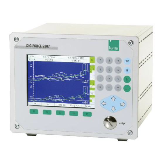
Intended use ® The DIGIFORCE 9307 is an instrument for monitoring repetitive production processes. Its core function is to record and analyze signals from processes in which physical variables, such as force, pressure or torque, vary as a function of displacement, angle or time according to a defined curve. The resultant measurement curve is analyzed using graphical evaluation elements such as windows, envelopes and thresholds. -
Page 14: Technical Data
0xF600 (Generic Device) You will find further information about PROFINET at: www.profibus.com. Model 9307 device data Bus connector RJ45 GSD file GSDML-V2.31-BURSTER-DIGIFORCE-9307-20160329-155500.xml Electrical safety Reverse voltage protection Air clearance/leakage paths To DIN EN 61010-1 Electrical isolation Between fieldbus and internal electronics... -
Page 15: Electromagnetic Compatibility
EN 61000-3-3:2013 Notes on CE labeling burster equipment carrying the CE mark meets the requirements of the EU directives and the harmonized European standards (EN) cited therein. The EU declarations of conformity are available to the relevant authorities as specified in the directives. A copy of the declaration of conformity is included in the relevant equipment documentation. -
Page 16: Installation
Please note that you can download various documents such as installation guidelines and specifications about PROFINET at PI: www.profibus.com. Connection of fieldbus lines burster devices with a PROFINET option have two RJ 45 connectors for the fieldbus connection. Meaning of LED states Blinking... -
Page 17: Configuration Of A Profinet Network
Configuration of a PROFINET network Diagram 1: Configuration of a PROFINET network of 154... -
Page 18: Configuration Menu In Digiforce ® 9307
® Configuration menu in DIGIFORCE 9307 To access the menu Start in measurement mode. After power on the measurement mode is always set. The display will look differently dependent on your settings or your last measurements. You can go to "Main setup menu" in measurement mode by pressing the [F5] key twice. In measurement mode, press the [F5] key twice. - Page 19 Select "PROFINET fieldbus Setup" menu with ▼ or ▲ and press [Enter]. Parameters ® PROFINET: DIGIFORCE 9307 responds solely to control signals (inputs) on the PROFINET interface ® PLC: DIGIFORCE 9307 responds solely to control signals (inputs) on the Control via PLC I/O interface.
-
Page 20: Profinet
DIGIFORCE equipment with the PROFINET option is supplied with a CD. This disk includes the device description file GSDML-V2.31-BURSTER-DIGIFORCE-9307-20160329-155500.xml (GSD file). This GSD file describes the physical properties of the device. The structure, contents and encoding of this device description data is standardized so that any Profinet devices can be configured using configuration tools from various manufacturers. -
Page 21: Data Conversion
Data conversion 6.3.1 Description of the data formats in this manual ® The terms PLC inputs and PLC outputs refer to the DIGIFORCE 9307 unit. These terms are reversed when referred to the Controller. The function of the PLC-In / PLC-Out bits is identical to the parallel PLC I/O ports on the unit itself and can ®... -
Page 22: Alarms
Alarms ® The DIGIFORCE 9307 supports two types of alarms: process alarms and diagnosis alarms. Currently two alarms are available. For the handling of alarms slot 200 is reserved. Process Alarm: Device Error is sent if a measurement channel is overloaded or the device is not ready for the measurement. -
Page 23: Profinet Data Protocol
DIGIFORCE 9307 operation manual, section 5.13 User defined values.) PLC inputs – Transfer from controller to device Four bytes of PLC-In data for the DIGIFORCE 9307 are always transferred from the PROFINET Controller ® ® to the DIGIFORCE 9307. -
Page 24: Plc Inputs Byte 1 (Controller To Device)
8.2.1 PLC inputs byte 1 (controller to device) PLC inputs Byte 1 (Controller Device) Valid values: IN_PROG0 Bit 0 LSB IN_PROG1 Bit 1 Set reserved bits to '0' IN_PROG2 Bit 2 IN_PROG3 Bit 3 IN_PROG4 Bit 4 reserved Bit 5 reserved Bit 6 reserved... -
Page 25: Plc Inputs Byte 3 (Controller To Device)
8.2.3 PLC inputs byte 3 (controller to device) PLC inputs Byte 3 (Controller Device) Valid values: IN_RESET Bit 0 LSB IN_PROG6* Bit 1 Set reserved bits to '0' IN_STEST Bit 2 IN_PROG5* Bit 3 reserved Bit 4 IN_TAREX Bit 5 IN_TAREY1 Bit 6 IN_TAREY2... -
Page 26: Plc Outputs - Transfer From Device To Controller
PLC outputs – Transfer from device to controller ® The data refers to the PLC output of the DIGIFORCE 9307. The data described here is the data transferred ® from the DIGIFORCE 9307 to the PROFINET controller. The function of the PLC-In / PLC-Out bits is identical to the parallel PLC I/O ports on the unit itself and can ®... -
Page 27: Plc Outputs Byte 3 (9307 Adjustable Outputs)
8.3.3 PLC outputs byte 3 (9307 adjustable outputs) PLC outputs Byte 3 (Device Controller) Valid values: PLC_OUT9 Bit 0 LSB PLC_OUT10 Bit 1 PLC_OUT11 Bit 2 PLC_OUT12 Bit 3 PLC_OUT13 Bit 4 PLC_OUT14 Bit 5 PLC_OUT15 Bit 6 PLC_OUT16 Bit 7 MSB 8.3.4 PLC outputs byte 4 (9307 adjustable outputs) -
Page 28: Default Assignment Of Output Byte [4..2] Adjustable Outputs
8.3.5 Default assignment of output byte [4..2] adjustable outputs 9307 adjustable PLC outputs default assignment PLC_OUT1 OUT_STROBE PLC_OUT2 OUT_OK_SENSORTEST PLC_OUT3 OUT_NOK_WINDOW_9 PLC_OUT4 OUT_PROG0 PLC_OUT5 OUT_PROG1 PLC_OUT6 OUT_PROG2 PLC_OUT7 OUT_PROG3 PLC_OUT8 OUT_PROG4 PLC_OUT9 OUT_S3 PLC_OUT10 OUT_S4 PLC_OUT11 OUT_NOK_WINDOW_8 PLC_OUT12 OUT_NOK_WINDOW_7 PLC_OUT13 OUT_NOK_WINDOW_6 PLC_OUT14 OUT_NOK_WINDOW_5... -
Page 29: Evaluation Info
Evaluation info The evaluation info (4 byte) contains the evaluation result of each element. 8.4.1 Evaluation info byte 1 Evaluation info byte 1 (Device Controller) Valid values: Window_1_NOK Bit 0 LSB Window_2_NOK Bit 1 Window_3_NOK Bit 2 Window_4_NOK Bit 3 Window_5_NOK Bit 4 Window_6_NOK... -
Page 30: Evaluation Info Byte 3
8.4.3 Evaluation info byte 3 Evaluation info byte 3 (Device Controller) Valid values: Threshold_3_NOK Bit 0 LSB Threshold_4_NOK Bit 1 Envelope_1_NOK Bit 2 Envelope_2_NOK Bit 3 Math_Evaluation_1_NOK Bit 4 Math_Evaluation_2_NOK Bit 5 Math_Evaluation_3_NOK Bit 6 Math_Evaluation_4_NOK Bit 7 MSB 8.4.4 Evaluation info byte 4 Evaluation info byte 4 (Device ... -
Page 31: Byte Reference List
Byte reference list Data from controller to device Byte Function Section Comments PLC inputs Byte 1 6.2.1 PLC inputs Byte 2 6.2.2 PLC inputs Byte 3 6.2.3 PLC inputs Byte 4 6.2.4 Data from device to controller Byte Function Section Comments PLC outputs Byte 1 6.3.1... - Page 32 Byte Function Section Comments M5-1 value_4 (1 Byte) see above User defined value in M5-1 value_4 (2 Byte) see above ® DIGIFORCE 9307 M5-1 value_4 (3 Byte) see above List M5-1 (32-Bit float) M5-1 value_4 (4 Byte) see above M5-1 value_5 (1 Byte) see above User defined value in...
- Page 33 Byte Function Section Comments ® DIGIFORCE 9307 M5-1 value_11 (2 Byte) see above List M5-1 (32-Bit float) M5-1 value_11 (3 Byte) see above M5-1 value_11 (4 Byte) see above M5-1 value_12 (1 Byte) see above User defined value in M5-1 value_12 (2 Byte) see above ®...
- Page 34 Byte Function Section Comments M5-2 value_6 (3 Byte) see above M5-2 value_6 (4 Byte) see above M5-2 value_7 (1 Byte) see above User defined value in M5-2 value_7 (2 Byte) see above ® DIGIFORCE 9307 M5-2 value_7 (3 Byte) see above List M5-2 (32-Bit float) M5-2 value_7 (4 Byte)
- Page 35 Byte Function Section Comments M1_Curvevalue_1 (4 Byte) see above M1_Curvevalue_2 (1 Byte) see above User defined value in M1_Curvevalue_2 (2 Byte) see above ® DIGIFORCE 9307 value in curve M1 M1_Curvevalue_2 (3 Byte) see above (32-Bit float) M1_Curvevalue_2 (4 Byte) see above M1_Curvevalue_3 (1 Byte)
- Page 36 Byte Function Section Comments Live value Channel Y2 (1 Byte) (32-Bit float) Live value Channel Y2 (2 Byte) Channel Y2 live value Updating rate of the live Live value Channel Y2 (3 Byte) values Live value Channel Y2 (4 Byte) of 154...
-
Page 37: Acyclic Profinet Services
• Transfer of component/worker/job data for logging • Retrieval of large amounts of process and curve data For further information and support for Siemens PLC integration please contact our service department at service@burster.com. Instrument configuration 9.1.1 General settings (Slot 30) - Page 38 Station name Stat14 right Tool counter 0 … 4294967296 Slot 30, Indices 21 to 40 Slot Index Description Value Meaning of value Type Standard value for 0 … tool counter 4294967296 EVENT! Writing an arbitrary byte Reset tool counter initiates action German English Language...
- Page 39 Slot Index Description Value Meaning of value Type Measurement menu function key Meas. menu page up definition F3 Meas. menu page down Meas. program incremental Meas. program decremental Tare X Tare Y Tare Y2 Measurement Start/Stop Acknowledge OK parts Acknowledge NOK parts Sensor test Reference measurement Edit mode...
- Page 40 Slot Index Description Value Meaning of value Type Meas. menu Meas. menu disabled display control Meas. menu enabled STATISTICS Meas. menu Meas. menu disabled display control Meas. menu enabled ORDER SHEET Meas. menu Meas. menu disabled display control Meas. menu enabled ROTARY SWITCH Slot 30, Indices 41 to 58 Slot...
- Page 41 Index Description Value Meaning of value Type Slot Access Access level disabled authorisation Access level enabled MEASUREMENT MODE Access Access level disabled authorisation Access level enabled EVALUATION Access Access level disabled authorisation Access level enabled SWITCHPOINTS Access Access level disabled authorisation TEST Access level enabled OPERATION...
- Page 42 Index Description Value Meaning of value Type Slot adj. PLC output 1 (Pin 2) A3 (switch program) adj. PLC output 1 (Pin 2) A4 (switch program) adj. PLC output 1 (Pin 2) Tare warning adj. PLC output 1 (Pin 2) Warning tool counter adj.
- Page 43 Index Description Value Meaning of value Type Slot adj. PLC output 1 (Pin 2) NOK threshold 2 adj. PLC output 1 (Pin 2) NOK threshold 3 adj. PLC output 1 (Pin 2) NOK threshold 4 adj. PLC output 1 (Pin 2) NOK envelope 1 adj.
- Page 44 Index Description Value Meaning of value Type Slot adj. PLC output 7 (Pin 12) see slot 59 adj. PLC output 8 (Pin 13) see slot 59 adj. PLC output 9 (Pin 16) see slot 59 adj. PLC output 10 (Pin 17) see slot 59 adj.
- Page 45 Index Description Value Meaning of value Type Slot Order sheet: Shift Shiftname_ Shift1 name Shift 1 Order sheet: Shift Shiftname_ Shift2 name Shift 2 Order sheet: Shift Shiftname_ Shift3 name Shift 3 Order sheet: Shift Shiftname_ Shift4 name Shift 4 Order sheet: Shift Shiftname_ Shift5 name Shift 5...
-
Page 46: Communication: Change Menu, Display Update, Fault Indication (Slot 32)
Index Description Value Meaning of value Type Slot Order sheet: Shift 0 … counter read-out 4294967296 quantity of NOK counts shift 4 Order sheet: Shift 0 … counter read-out 4294967296 quantity of NOK counts shift 5 Order sheet: Shift 0 … counter read-out 4294967296 quantity of NOK counts... -
Page 47: Minimal Setup Menu (Slot 33)
Index Description Value Meaning of value Type Slot 0x00000020 Timeout Receive Timer U32x Timeout Response Timer U32x 0x00000040 Invalid ! or ? U32x 0x00000080 Invalid configuration U32x 0x00000100 0x00000200 Scaling fault U32x No valid measurements are U32x 0x00000400 available A/D converter overdriven U32x 0x00000800 Fault reading from EEPROM... - Page 48 Index Description Value Meaning of value Type Slot Channel settings Terminals: channel X A, strain gauge A, Potentiometer Note: First make the A, standard signal settings in indices 10, B, strain gauge 11, 12, then initiate B, Potentiometer with index 13! B, standard signal C, Incr.
- Page 49 Index Description Value Meaning of value Type Slot Channel settings Terminals: channel Y1 A, strain gauge A, Potentiometer Note: First make the A, standard signal settings in indices 10, B, strain gauge 11, 12, then initiate B, Potentiometer with index 13! B, standard signal C, Incr.
- Page 50 Index Description Value Meaning of value Type Slot Filter channel Y1 5 Hz filter Note: Entry is not 10 Hz filter available for the 25 Hz filter channel settings 50 Hz filter "Time" and 100 Hz filter "Incremental". 200 Hz filter 400 Hz filter 800 Hz filter Filter channel Y2...
- Page 51 Index Description Value Meaning of value Type Slot Set unit channel X User defined unit 1 User defined unit 2 Note: Entry is not User defined unit 3 available for the channel settings "Time" and "Resistance". Set unit channel Y1 User defined unit 1 User defined unit 2 Note: Entry is not...
-
Page 52: Channel Settings "Potentiometer" (Slot 35)
Index Description Value Meaning of value Type Slot Take the tare value for EVENT! channel Y1 and return the measured value Note: Entry is not available for the channel settings "Time", "Incremental" and "Resistance". Take the tare value for EVENT! channel Y2 and return the measured value Note: Entry is not... -
Page 53: Channel Settings "Standard Signal" (Slot 36)
9.1.6 Channel settings “Standard signal” (Slot 36) Slot Index Description Value Meaning of value Type Not possible 1 - 9 Reserved Standard signal input 5 V input range channel X 10 V input range Standard signal input 5 V input range channel Y1 10 V input range Standard signal input... - Page 54 Index Description Value Meaning of value Type Slot Strain gauge sensitivity 0.01 ... 100.0 IEEE754 Float channel X Strain gauge sensitivity IEEE754 Float 0.01 ... 100.0 channel Y1 Strain gauge sensitivity IEEE754 Float 0.01 ... 100.0 channel Y2 Level (elect.) strain 0.01 ...
-
Page 55: Channel Settings "Resistance" (Slot 38)
9.1.8 Channel settings “Resistance” (Slot 38) Slot Index Description Value Meaning of value Type Not possible 1 - 9 Reserved Resistance input range 200 mOhm range channel X 2 kOhm range 100 kOhm range Resistance input range 200 mOhm range channel Y1 2 kOhm range 100 kOhm range... -
Page 56: Channel Settings "Incremental" (Slot 40)
Index Description Value Meaning of value Type Slot Piezo short-circuit Do not short-circuit piezo input on/to channel X Short-circuit piezo input Piezo short-circuit Do not short-circuit piezo input on/to channel Y1 Short-circuit piezo input Piezo short-circuit Do not short-circuit piezo input on/to channel Y2 Short-circuit piezo input 9.1.10 Channel settings “Incremental”... - Page 57 Index Description Value Meaning of value Type Slot Incremental Set to value at start off/on channel Y2 Incremental between Float value, set value at start - 9999999.0 Float according to IEEE754 channel X 9999999.0 Incremental between Float value, set value at start - 9999999.0 Float according to IEEE754 channel Y1...
-
Page 58: Channel Settings "Ssi" (Slot 41)
Index Description Value Meaning of value Type Slot Incremental termination resistor off/on channel Y1 Incremental termination resistor off/on channel Y2 Direction of counting positive positive/negative negative channel X Direction of counting positive positive/negative negative channel X1 Direction of counting positive positive/negative negative channel Y2... - Page 59 Index Description Value Meaning of value Type Slot SSI code channel X Binary Gray code Note: At the end, settings must be initiated through a write access to indices 37/38/39. SSI code channel Y1 Binary Gray code Note: At the end, settings must be initiated through a write access to indices...
- Page 60 Index Description Value Meaning of value Type Slot SSI parity channel X even Note: At the end, settings must be initiated through a write access to indices 37/38/39. SSI parity channel Y1 even Note: At the end, settings must be initiated through a write access to indices 37/38/39.
- Page 61 Index Description Value Meaning of value Type Slot SSI resolution between Float value, channel X - 9999999.0 Float according to IEEE754 Note: Only permitted 9999999.0 for displacement sensors! At the end, settings must be initiated through a write access to indices 37/38/39.
- Page 62 Index Description Value Meaning of value Type Slot SSI bit number angle 0 ... 32 Integer value singleturn or displacement channel Note: At the end, settings must be initiated through a write access to indices 37/38/39. SSI bit number angle 0 ...
- Page 63 Index Description Value Meaning of value Type Slot SSI bit number 0 ... 32 Integer value rotations for multiturn angle channel Y2 Note: At the end, settings must be initiated through a write access to indices 37/38/39. Check & initiate SSI Writing an arbitrary byte EVENT! settings channel X...
-
Page 64: Channel Settings "Endat" (Slot 42)
9.1.12 Channel settings “EnDat” (Slot 42) Slot Index Description Value Meaning of value Type Not possible 1 .. 9 Reserved Read-out EnDat EVENT! Writing an arbitrary byte sensor data channel X initiates action Note: At the end, settings must be initiated through a write access to index 16. - Page 65 Index Description Value Meaning of value Type Slot Copy EnDat sensor EVENT! Writing an arbitrary byte setup channel X initiates action Note: Sensor data must be read beforehand, and the clock frequency must be set. Copy EnDat sensor EVENT! Writing an arbitrary byte setup channel Y1 initiates action Note: Sensor data...
- Page 66 Index Description Value Meaning of value Type Slot EnDat standard EnDat 2.1 channel Y2 EnDat 2.2 Note: See comment at the end of the slot. EnDat name of sensor "angle z-axis" channel X Note: Only available with EnDat 2.2! See comment at the end of the slot.
- Page 67 Index Description Value Meaning of value Type Slot EnDat sensor type Displacement channel Y1 Singelturn encoder Multiturn encoder Note: See comment at the end of the slot. EnDat sensor type Displacement channel Y2 Singelturn encoder Multiturn encoder Note: See comment at the end of the slot.
- Page 68 Index Description Value Meaning of value Type Slot EnDat bit number 0 ... 32 Integer value angle multiturn channel Note: See comment at the end of the slot. EnDat bit number 0 ... 32 Integer value angle multiturn channel Note: See comment at the end of the slot.
- Page 69 Index Description Value Meaning of value Type Slot EnDat unit of GP (grating period) measuring length µm (Micrometer) channel X mm (Millimeter) m (Meter) Note: See comment at the end of the slot. EnDat unit of GP (grating period) measuring length µm (Micrometer) channel Y1 mm (Millimeter)
- Page 70 Index Description Value Meaning of value Type Slot Transmit EnDat EVENT! Writing an arbitrary byte manual sensor setup initiates action channel Y1 Note: Sensor data must be entered beforehand into the indices 19 ... 54! Transmit EnDat EVENT! Writing an arbitrary byte manual sensor setup initiates action channel Y2...
- Page 71 Index Description Value Meaning of value Type Slot 19 ... Comment on slots 19 … 54: Reading these entries only makes sense if data has been read from the sensor beforehand (indices 10, 11, 12) It is also possible to write sensor data here.
-
Page 72: Tare (Slot 43)
9.1.13 Tare (Slot 43) Slot Index Description Value Meaning of value Type Not possible 1 .. 9 Reserved Tare at meas. start channel X Tare at meas. start channel Y1 Tare at meas. start channel Y2 Standard value for tare between Float value, channel X... -
Page 73: Measurement Mode (Slot 44)
9.1.14 Measurement mode (Slot 44) Slot Index Description Value Meaning of value Type Not possible 1 .. 9 Reserved X sampling off/on X sample rate between 0.0 Float value Float according to IEEE754 9999999.0 Y1 sampling off/on Y1 sample rate Float value between 0.0 Float according to IEEE754... - Page 74 Index Description Value Meaning of value Type Slot Set trigger line Y1 between Float value -9999999.0 Float according to IEEE754 9999999.0 Set trigger line Y2 between Float value -9999999.0 Float according to IEEE754 9999999.0 Pretrigger display on/off Set return point XMIN XMAX YMIN...
-
Page 75: Evaluation Window 1 (Slot 45)
Index Description Value Meaning of value Type Slot Set Y1 stop value for between Float value internal stop -9999999.0 Float according to IEEE754 9999999.0 Set Y2 stop value for between Float value internal stop -9999999.0 Float according to IEEE754 9999999.0 Set the "stop"... - Page 76 Index Description Value Meaning of value Type Slot Window 1 entry left Note: At the end, entry must be adopted through index 24. Window 1 entry right Note: At the end, entry must be adopted through index 24. Window 1 entry bottom Note: At the end, entry must be adopted through index 24.
- Page 77 Index Description Value Meaning of value Type Slot Window 1 online evaluation left - right right - left bottom - top top - bottom Window 1 1 or 2 online signal number Window 1 Low active Online signal level High active Window 1 "Evaluate Evaluate all passages only first passage"...
-
Page 78: Evaluation Window 2 (Slot 46)
9.1.16 Evaluation window 2 (Slot 46) Slot Index Description Value Meaning of value Type Not possible 1 .. 9 Reserved 10 ... See slot 45 9.1.17 Evaluation window 3 (Slot 47) Index Description Value Meaning of value Type Slot Not possible 1 .. -
Page 79: Evaluation Window 7 (Slot 51)
9.1.21 Evaluation window 7 (Slot 51) Slot Index Description Value Meaning of value Type Not possible 1 .. 9 Reserved 10 ... See slot 45 9.1.22 Evaluation window 8 (Slot 52) Index Description Value Meaning of value Type Slot Not possible 1 .. - Page 80 Index Description Value Meaning of value Type Slot Trapezoid X1 limit between Float value Xmax -9999999.0 Float according to IEEE754 Note: At the end, entry 9999999.0 must be adopted through index 17. Trapezoid X1 Y limit between Float value max left -9999999.0 Float according to IEEE754 Note: At the end, entry...
-
Page 81: Evaluation Trapezoid Window X2 (Slot 56)
Index Description Value Meaning of value Type Slot Trapezoid X1 exit right Note: At the end, entry must be adopted through index 22. Trapezoid X1 copy EVENT Writing an arbitrary byte entry/exit initiates action Note: Values entered into indices 16 - 21 are adopted. - Page 82 Index Description Value Meaning of value Type Slot Trapezoid Y1 X limit between Float value min top -9999999.0 Float according to IEEE754 Note: At the end, entry 9999999.0 must be adopted through index 17. Trapezoid Y1 X limit between Float value max top -9999999.0 Float according to IEEE754...
-
Page 83: Evaluation Trapezoid Window Y2 (Slot 58)
Index Description Value Meaning of value Type Slot Trapezoid Y1 copy EVENT Writing an arbitrary byte entry/exit initiates action Note: Values entered into indices 16 - 21 are adopted Trapezoid Y1 evaluation Trapezoid Y1 Curve Forward segment for Return evaluation Complete curve Trapezoid Y1 Evaluate all passages... - Page 84 Index Description Value Meaning of value Type Slot Threshold 1 limit between Float value For type X: Ymax -9999999.0 Float according to IEEE754 For type Y: Xmax 9999999.0 Note: At the end, entry must be adopted through index 15. Threshold 1 EVENT Writing an arbitrary byte copy position and limits...
-
Page 85: Evaluation Threshold 2 (Slot 60)
Index Description Value Meaning of value Type Slot Threshold 1 between Float value Delta Y bend 0.0 and Float according to IEEE754 9999999.0 Threshold 1 Calculate absolute maximum Note: Only for type Y Threshold 1 Calculate absolute minimum Note: Only for type Y Threshold 1 Calculate local maximum... -
Page 86: Evaluation Threshold 3 (Slot 61)
9.1.31 Evaluation threshold 3 (Slot 61) Slot Index Description Value Meaning of value Type Not possible 1 .. 9 Reserved 10 ... See slot 59 9.1.32 Evaluation threshold 4 (Slot 62) Slot Index Description Value Meaning of value Type Not possible 1 .. - Page 87 Index Description Value Meaning of value Type Slot Math. function between Float value Constant 3 -9999999.0 Float according to IEEE754 9999999.0 Math. function between Float value Constant 4 -9999999.0 Float according to IEEE754 9999999.0 Math. function between Float value Constant 5 -9999999.0 Float according to IEEE754 9999999.0...
- Page 88 Index Description Value Meaning of value Type Slot Math. function Copy EVENT Writing an arbitrary byte formula 1 initiates action Note: Values entered into indices 20 - 22 are adopted Math. function formula Integer value See operand table in appendix row 2 operand A Note: At the end, entry must be adopted...
- Page 89 Index Description Value Meaning of value Type Slot Math. function Copy EVENT Writing an arbitrary byte formula 3 initiates action Note: Values entered into indices 28 - 30 are adopted. Math. function formula Integer value See operand table in appendix row 4 operand A Note: At the end, entry must be adopted...
- Page 90 Index Description Value Meaning of value Type Slot Math. function Copy EVENT Writing an arbitrary byte formula 5 initiates action Note: Values entered into indices 36 - 38 are adopted. Math. function formula Integer value See operand table in appendix row 6 operand A Note: At the end, entry must be adopted...
- Page 91 Index Description Value Meaning of value Type Slot Math. function Copy EVENT Writing an arbitrary byte formula 7 initiates action Note: Values entered into indices 44 - 46 are adopted. Math. function formula Integer value See operand table in appendix row 8 operand A Note: At the end, entry must be adopted...
- Page 92 Index Description Value Meaning of value Type Slot Math. function Copy EVENT Writing an arbitrary byte formula 9 initiates action Note: Values entered into indices 52 - 54 are adopted. Math. function formula Integer value See operand table in appendix row 10 operand A Note: At the end, entry must be adopted...
- Page 93 Index Description Value Meaning of value Type Slot Math. function Copy EVENT Writing an arbitrary byte evaluation1 initiates action Note: Values entered into indices 60 - 62 are adopted. Math. function Integer value See operand table in appendix Evaluation operand 2 Note: At the end, entry must be adopted through index 67.
- Page 94 Index Description Value Meaning of value Type Slot Math. function Copy EVENT Writing an arbitrary byte evaluation 3 initiates action Note: Values entered into indices 68 - 70 are adopted. Math. function Integer value See operand table in appendix Evaluation operand 4 Note: At the end, entry must be adopted through index 75.
- Page 95 Index Description Value Meaning of value Type Slot Math. function Copy EVENT Writing an arbitrary byte evaluation 5 initiates action Note: Values entered into indices 76 - 78 are adopted. Math. function Integer value See operand table in appendix Evaluation operand 6 Note: At the end, entry must be adopted through index 83.
-
Page 96: Tolerance Band For Evaluation Elements (Slot 76)
9.1.38 Tolerance band for evaluation elements (Slot 76) Slot Index Description Value Meaning of value Type Not possible 1 .. 9 Reserved Tolerance band X between Float value 0.0 and Float according to IEEE754 Note: At the end, entry 9999999.0 must be adopted through index 13. -
Page 97: Realtime Switchpoints S2 (Slot 78)
Index Description Value Meaning of value Type Slot Switchpoint 1 Absolute reference reference Trigger reference Note: At the end, entry must be adopted through index 14. Switchpoint 1 Copy EVENT Writing an arbitrary byte settings initiates action Note: Values entered into indices 10 - 13 are adopted. -
Page 98: Setup User-Defined Values (Slot 82)
Index Description Value Meaning of value Type Slot Sensor test Channel Y1 on/off Sensor test Channel Y2 on/off Sensor test Channel X Writing an arbitrary byte EVENT measure reference initiates action value Sensor test Channel EVENT Writing an arbitrary byte Y1 measure reference initiates action value... - Page 99 Index Description Value Meaning of value Type Slot User-defined values Integer value See operand table in appendix value 4 User-defined values See operand table in appendix Integer value value 5 User-defined values See operand table in appendix Integer value value 6 User-defined values Integer value See operand table in appendix...
-
Page 100: Copy/Initialize Measurement Programs (Slot 83)
Index Description Value Meaning of value Type Slot User-defined values Integer value See operand table in appendix value 28 User-defined values See operand table in appendix Integer value value 29 User-defined values See operand table in appendix Integer value value 30 9.1.45 Copy/initialize measurement programs (Slot 83) Slot Index... -
Page 101: Reference Curve Y1, Y2 (Slot 84 To 88)
Index Description Value Meaning of value Type Slot Initialize selected EVENT Writing an arbitrary byte programs initiates action Note: Initializing according to indices 11 - 12. Initialize all EVENT Writing an arbitrary byte measurement initiates action programs 9.1.46 Reference curve Y1, Y2 (Slot 84 to 88) Slot/index data on request 9.1.47 Test operation (Slot 89) Slot... - Page 102 Index Description Value Meaning of value Type Slot Fix scale Ymin Float value Float according to IEEE754 channel Y1 Note: At the end, entry must be adopted through index 15. Fix scale Ymax Float value Float according to IEEE754 channel Y1 Note: At the end, entry must be adopted through index 15.
-
Page 103: Measurement Results
Measurement results 9.2.1 Status of measurement Slot Index Description Value Meaning of value Type Not possible 1…9 Reserved Index of the last 16 Bit Integer 0 means that there is no measured value of the value measurement curve current curve Caution: The number of the pair of values is shown on the display. -
Page 104: Further Information For Current Pretrigger Curve
Index Description Value Meaning of value Type Slot Index of the last 16 Bit Integer measured value of the value curve Caution: The number of the pair of values is shown on the display. The index begins at 0, the number at 1! Status overdrive of the No overdrive A/D converter... -
Page 105: General Curve Data Channel Y1
9.2.4 General curve data channel Y1 Slot Index Description Value Meaning of value Type Not possible 1…9 Reserved X-minimum, X- Float value Float according to IEEE754 coordinate X-minimum, Y1- Float value Float according to IEEE754 coordinate X-maximum, X- Float value Float according to IEEE754 coordinate X-maximum, Y1-... - Page 106 Index Description Value Meaning of value Type Slot User-defined value 1 String with Designator = "0" means that name no value is defined for this designator of value number the value User-defined value 1 Float value Float according to IEEE754 measurement value User-defined value 1 String with...
- Page 107 Index Description Value Meaning of value Type Slot User-defined value 5 String with See operand table in unit max. 4 appendix. characters, e.g. "N" or "inch" User-defined value 6 String with Designator = "0" means that name no value is defined for this designator of value number the value...
- Page 108 Index Description Value Meaning of value Type Slot User-defined value 10 Float value Float according to IEEE754 measurement value User-defined value 10 See operand table in String with unit max. 4 appendix. characters, e.g. "N" or "inch" User-defined value 11 String with Designator = "0"...
- Page 109 Index Description Value Meaning of value Type Slot User-defined value 15 String with Designator = "0" means that name no value is defined for this designator of value number the value User-defined value 15 Float value Float according to IEEE754 measurement value User-defined value 15 String with...
- Page 110 Index Description Value Meaning of value Type Slot User-defined value 19 String with See operand table in unit max. 4 appendix. characters, e.g. "N" or "inch" User-defined value 20 String with Designator = "0" means that name no value is defined for this designator of value number the value...
- Page 111 Index Description Value Meaning of value Type Slot User-defined value 24 Float value Float according to IEEE754 measurement value User-defined value 24 See operand table in String with unit max. 4 appendix. characters, e.g. "N" or "inch" User-defined value 25 String with Designator = "0"...
-
Page 112: Statistic Measurement Result Evaluation Element Window 1 (Evelem 1)
Index Description Value Meaning of value Type Slot User-defined value 29 String with Designator = "0" means that name no value is defined for this designator of value number the value User-defined value 29 Float value Float according to IEEE754 measurement value User-defined value 29 String with... -
Page 113: Statistic Measurement Result Evaluation Element Window 9 (Evelem 9)
9.2.15 Statistic measurement result evaluation element window 9 (EvElem 9) Slot/index data on request 9.2.16 Statistic measurement result evaluation element window 10 (EvElem 10) Slot/index data on request 9.2.17 Statistic measurement result evaluation element threshold 1 (EvElem 11) Slot/index data on request 9.2.18 Statistic measurement result evaluation element threshold 2 (EvElem 12) Slot/index data on request 9.2.19 Statistic measurement result evaluation element threshold 3 (EvElem 13) -
Page 114: Statistic Measurement Result Evaluation Element Mathematical Calculation 1 (Evelem 21)
9.2.27 Statistic measurement result evaluation element mathematical calculation 1 (EvElem 21) Slot/index data on request 9.2.28 Statistic measurement result evaluation element mathematical calculation 2 (EvElem 22) Slot/index data on request 9.2.29 Statistic measurement result evaluation element mathematical calculation 3 (EvElem 23) Slot/index data on request 9.2.30 Statistic measurement result evaluation element mathematical calculation 4 (EvElem 24) -
Page 115: Read-Out Curve Coordinates Of Current Measurement Curve With Single Array Access
9.2.33 Read-out curve coordinates of current measurement curve with single array access Note that there are two different ways to read the coordinates of the measurement curve: • Read complete coordinates with a single array access (Array size up to 20 KB) •... - Page 116 Index Description Value Meaning of value Type Slot Not possible 1…9 Reserved Write access: EVENT! If a curve is to be Writing any read, it must be two arbitrary prepared through a bytes write access before initiates the curve is first read. action Read access: Index of the last...
-
Page 117: 9.2.34 Read-Out Y1-Coordinates Of Current Measurement Curve
Index Description Value Meaning of value Type Slot Write access: Integer value Desired group of 200 0 … 24 coordinates. For example, if coordinates 600 … 799 are to be displayed, there must be a 3 here. Query the maximum number of value pairs under slot 132/10. -
Page 118: 9.2.36 Read-Out X-Coordinates Of Current Pretrigger Curve
9.2.36 Read-out X-coordinates of current pretrigger curve Slot Index Description Value Meaning of value Type Not possible 1…9 Reserved Write access: EVENT! If a curve is to be Writing any read, it must be two arbitrary prepared through a bytes write access before initiates the curve is first read. -
Page 119: 9.2.37 Read-Out Y1-Coordinates Of Current Pretrigger Curve
Index Description Value Meaning of value Type Slot 0. coordinate of Float value Float according to IEEE754 group of coordinates 1. coordinate of Float according to IEEE754 Float value group of coordinates 2. coordinate of Float according to IEEE754 Float value group of coordinates 3. -
Page 120: Evaluation Results Window 2
Index Description Value Meaning of value Type Slot Window 1 exit of Float value Float according to IEEE754 curve X-coordinate Window 1 exit of Float according to IEEE754 Float value curve Y-coordinate Window 1 absolute Float according to IEEE754 Float value Y- maximum in window X-coordinate... -
Page 121: Evaluation Results Window 3
9.2.41 Evaluation results window 3 Slot Index Description Value Meaning of value Type Not possible 1…9 Reserved 10… See slot 138 9.2.42 Evaluation results window 4 Slot Index Description Value Meaning of value Type Not possible 1…9 Reserved 10… See slot 138 9.2.43 Evaluation results window 5 Slot Index... -
Page 122: Evaluation Results Window 8
9.2.46 Evaluation results window 8 Slot Index Description Value Meaning of value Type Not possible 1…9 Reserved 10… See slot 138 9.2.47 Evaluation results window 9 Slot Index Description Value Meaning of value Type Not possible 1…9 Reserved 10… See slot 138 9.2.48 Evaluation results window 10 Slot Index... -
Page 123: Evaluation Results Threshold 2
Index Description Value Meaning of value Type Slot threshold Y-coordinate Threshold 1 absolute Float according to IEEE754 Float value Y-minimum in threshold X-coordinate Threshold 1 absolute Float value Float according to IEEE754 Y-minimum in threshold Y-coordinate Threshold 1 local Y- Float value Float according to IEEE754 maximum in... -
Page 124: Evaluation Results Threshold 3
9.2.51 Evaluation results threshold 3 Slot Index Description Value Meaning of value Type Not possible 1…9 Reserved 10… See slot 148 9.2.52 Evaluation results threshold 4 Slot Index Description Value Meaning of value Type Not possible 1…9 Reserved 10… See slot 148 9.2.53 Evaluation results trapezoid window X1 Slot Index... -
Page 125: 9.2.55 Evaluation Results Trapezoid Window Y1
9.2.55 Evaluation results trapezoid window Y1 Slot Index Description Value Meaning of value Type Not possible 1…9 Reserved Trapezoid Y1 evaluation results OK/NOK Trapezoid Y1 NOK 32bit-Integer counter value >= 0 Trapezoid Y1 entry Float according to IEEE754 Float value coordinate X-coordinate Trapezoid Y1 entry... -
Page 126: Evaluation Results Envelope 2
Index Description Value Meaning of value Type Slot Envelope 1 exit Float value Float according to IEEE754 coordinate X-coordinate Envelope 1 exit Float value Float according to IEEE754 coordinate Y-coordinate 9.2.58 Evaluation results envelope 2 Index Description Value Meaning of value Type Slot Not possible... - Page 127 Index Description Value Meaning of value Type Slot evaluation element 1 X-coord. minima 3 Rotary switch Float according to IEEE754 Float value evaluation element 1 X-coord. minima 4 Rotary switch Float value Float according to IEEE754 evaluation element 1 X-coord. minima 5 Rotary switch Float value Float according to IEEE754...
- Page 128 Index Description Value Meaning of value Type Slot Rotary switch Float value Float according to IEEE754 evaluation element 1 X-coord. minima 9 Rotary switch Float value Float according to IEEE754 evaluation element 1 X-coord. minima 10 Rotary switch Float value Float according to IEEE754 evaluation element 1 X-coord.
- Page 129 Index Description Value Meaning of value Type Slot Rotary switch Float value Float according to IEEE754 evaluation element 1 X-coord. minima 26 Rotary switch Float value Float according to IEEE754 evaluation element 1 X-coord. minima 27 Rotary switch Float value Float according to IEEE754 evaluation element 1 X-coord.
- Page 130 Index Description Value Meaning of value Type Slot Rotary switch Float value Float according to IEEE754 evaluation element 1 Y-coord. minima 11 Rotary switch Float value Float according to IEEE754 evaluation element 1 Y-coord. minima 12 Rotary switch Float value Float according to IEEE754 evaluation element 1 Y-coord.
- Page 131 Index Description Value Meaning of value Type Slot Rotary switch Float value Float according to IEEE754 evaluation element 1 Y-coord. minima 28 Rotary switch Float value Float according to IEEE754 evaluation element 1 Y-coord. minima 29 Rotary switch Float value Float according to IEEE754 evaluation element 1 Y-coord.
- Page 132 Index Description Value Meaning of value Type Slot Rotary switch Float value Float according to IEEE754 evaluation element 1 X-coord. maxima 13 Rotary switch Float value Float according to IEEE754 evaluation element 1 X-coord. maxima 14 Rotary switch Float value Float according to IEEE754 evaluation element 1 X-coord.
- Page 133 Index Description Value Meaning of value Type Slot Rotary switch Float value Float according to IEEE754 evaluation element 1 X-coord. maxima 30 Rotary switch Float value Float according to IEEE754 evaluation element 1 X-coord. maxima 31 Rotary switch Float value Float according to IEEE754 evaluation element 1 X-coord.
- Page 134 Index Description Value Meaning of value Type Slot Rotary switch Float value Float according to IEEE754 evaluation element 1 Y-coord. maxima 15 Rotary switch Float value Float according to IEEE754 evaluation element 1 Y-coord. maxima 16 Rotary switch Float value Float according to IEEE754 evaluation element 1 Y-coord.
-
Page 135: Evaluation Results Rotary Switch Evaluation Element 2
Index Description Value Meaning of value Type Slot Rotary switch Float value Float according to IEEE754 evaluation element 1 Y-coord. maxima 32 9.2.60 Evaluation results rotary switch evaluation element 2 Index Description Value Meaning of value Type Slot Not possible 1…9 Reserved 10…... -
Page 136: Combined Results (Common Curve Data And Evalution Elements)
9.2.62 Combined results (common curve data and evalution elements) Meaning Slot Index Description Value Type of value Not possible 1…9 Reserved Combined results: The data is bit coded and STRUCT general curve transmitted as STRUCT. data Y1 X-minimum, X-coord. (FL) FLOATS X-minimum, Y1-coord. - Page 137 Meaning Slot Index Description Value Type of value Combined results: See index 12 STRUCT window 4 Combined results: See index 12 STRUCT window 5 Combined results: See index 12 STRUCT window 6 Combined results: STRUCT See index 12 window 7 Combined results: STRUCT See index 12...
- Page 138 Meaning Slot Index Description Value Type of value Combined results: See index 26 STRUCT trapezoid window Combined results: STRUCT The data is bit coded and trapezoid window transmitted as STRUCT: Evaluation result (UINT32) Entry X-coord. (FL) Entry Y-coord. (FL) Exit X-coord. (FL) Exit Y-coord.
-
Page 139: Appendix
Appendix 10.1 Operand table for mathematical functions Number ID of operant Intermediate Result 1 Intermediate Result 2 Intermediate Result 3 Intermediate Result 4 Intermediate Result 5 Intermediate Result 6 Intermediate Result 7 Intermediate Result 8 Intermediate Result 9 Intermediate Result 10 Constant 1 Constant 2 Constant 3... - Page 140 Number ID of operant General curve data Y1 – End Y General curve data Y1 – Abs. Xmax X-coordinate General curve data Y1 – Abs. Xmax Y-coordinate General curve data Y1 – Abs. Xmin X-coordinate General curve data Y1 – Abs. Xmin Y-coordinate General curve data Y1 –...
- Page 141 Number ID of operant Window 1 – Entry X Window 1 – Entry Y Window 1 – Exit X Window 1 – Exit Y Window 1 – Abs. minimum X Window 1 – Abs. minimum Y Window 1 – Abs. maximum X Window 1 –...
- Page 142 Number ID of operant Window 2 – Abs. maximum Y Window 2 – Loc. minimum X Window 2 – Loc. minimum Y Window 2 – Loc. maximum X Window 2 – Loc. maximum Y Window 2 – Bend X Window 2 – Bend Y Window 2 –...
- Page 143 Number ID of operant Window 3 – Mean value Y Window 3 – Gradient Window 3 – Area Window 3 – Coordinate Xmin Window 3 – Coordinate Xmax Window 3 – Coordinate Ymin Window 3 – Coordinate Ymax Window 4 – Entry X Window 4 –...
- Page 144 Number ID of operant Window 5 – Entry X Window 5 – Entry Y Window 5 – Exit X Window 5 – Exit Y Window 5 – Abs. minimum X Window 5 – Abs. minimum Y Window 5 – Abs. maximum X Window 5 –...
- Page 145 Number ID of operant 1006 Window 6 – Abs. maximum X 1007 Window 6 – Abs. maximum Y 1008 Window 6 – Loc. minimum X 1009 Window 6 – Loc. minimum Y 1010 Window 6 – Loc. maximum X 1011 Window 6 –...
- Page 146 Number ID of operant 1113 Window 7 – Bend Y 1114 Window 7 – Mean value Y 1115 Window 7 – Gradient 1116 Window 7 – Area 1117 Window 7 – Coordinate Xmin 1118 Window 7 – Coordinate Xmax 1119 Window 7 –...
- Page 147 Number ID of operant 1220 Window 8 – Coordinate Ymax 1300 Window 9 – Entry X 1301 Window 9 – Entry Y 1302 Window 9 – Exit X 1303 Window 9 – Exit Y 1304 Window 9 – Abs. minimum X 1305 Window 9 –...
- Page 148 Number ID of operant 1405 Window 10 – Abs. minimum Y 1406 Window 10 – Abs. maximum X 1407 Window 10 – Abs. maximum Y 1408 Window 10 – Loc. minimum X 1409 Window 10 – Loc. minimum Y 1410 Window 10 –...
- Page 149 Number ID of operant 1601 Trapezoid window X2 – Entry Y 1602 Trapezoid window X2 – Exit X 1603 Trapezoid window X2 – Exit Y 1604 Trapezoid window X2 – Coordinate Xmin 1605 Trapezoid window X2 – Coordinate Xmax 1606 Trapezoid window X2 –...
- Page 150 Number ID of operant 1808 Trapezoid window Y2 – Coordinate Xmax bottom 1809 Trapezoid window Y2 – Coordinate Xmax top 1900 Threshold 1 – Pass X 1901 Threshold 1 – Pass Y 1902 Threshold 1 – Abs. minimum X 1903 Threshold 1 –...
- Page 151 Number ID of operant 2007 Threshold 2 – Loc. minimum Y 2008 Threshold 2 – Loc. maximum X 2009 Threshold 2 – Loc. maximum Y 2010 Threshold 2 – Bend X 2011 Threshold 2 – Bend Y 2012 Threshold 2 – Mean value Y 2013 Threshold 2 –...
- Page 152 Number ID of operant 2117 Threshold 3 – Coordinate Ymax 2200 Threshold 4 – Pass X 2201 Threshold 4 – Pass Y 2202 Threshold 4 – Abs. minimum X 2203 Threshold 4 – Abs. minimum Y 2204 Threshold 4 – Abs. maximum X 2205 Threshold 4 –...
- Page 153 Number ID of operant 2401 Envelope 2 – Entry Y 2402 Envelope 2 – Exit X 2403 Envelope 2 – Exit Y 2404 Envelope 2 – Coordinate Start X 2405 Envelope 2 – Coordinate End X of 154...
-
Page 154: Error Codes
WRITE_ACCESS_INVALIDINDEX 0xDF80B000 This index is not specified WRITE_ACCESS_INVALIDLENGTH 0xDF80B100 Please check the length of the date which can be accepted by the DIGIFORCE 9307 WRITE_ACCESS_INVALIDSLOT_SUBSLOT 0xDF80B200 Reading from this slot/subslot is not supported Note: Only subslot 1 is supported WRITE_ACCESS_DENIED...
Need help?
Do you have a question about the DIGIFORCE 9307 and is the answer not in the manual?
Questions and answers