Sign In
Upload
Manuals
Brands
Burster Manuals
Measuring Instruments
DIGIFORCE 9307
Burster DIGIFORCE 9307 Measurement Sensor Manuals
Manuals and User Guides for Burster DIGIFORCE 9307 Measurement Sensor. We have
5
Burster DIGIFORCE 9307 Measurement Sensor manuals available for free PDF download: Operation Manual, Operation Manuals
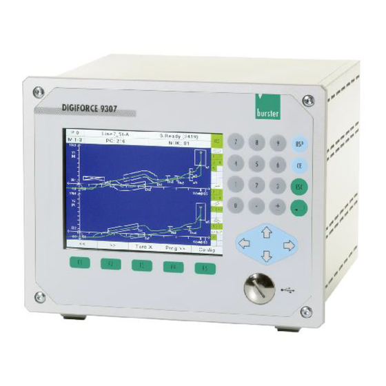
burster DIGIFORCE 9307 Operation Manual (503 pages)
instrument for monitoring repetitive production processes
Brand:
burster
| Category:
Measuring Instruments
| Size: 4 MB
Table of Contents
Table of Contents
3
1 For Your Safety
13
Symbols Used in the Instruction Manual
13
Signal Words
13
Pictograms
13
Symbols and Precautionary Statements on the Instrument
14
2 Introduction
15
Introduction General Safety Instructions
15
Intended Use
16
Electromagnetic Compatibility
16
Interference Immunity
16
Emitted Interference
16
Notes on CE Labeling
16
3 General Communication Info
17
Communication Via RS232
17
Communication Via the USB Port
19
The Communications Protocol
20
Establishing a Connection
20
Selection with Response
21
Fast Selection
23
Polling
24
Data Transfer
24
Timers
25
Terminating a Connection
25
Communication Via the Ethernet Port
26
The UDP Transmission Protocol
26
4 Commands
31
Device Status
33
FSTA - 9307 Query Device Status
33
TEMP Query the Current Device Temperature (V2016.0.2 and Higher)
34
General Commands
34
GOTO - Go to Measurement or Setup Menu
34
UPDA - Perform Display Update
35
MEFR - Enable Start of Measurement On/Off
35
EIZA - Query or Reset Power up Counter
36
EIGE - Query or Reset Counter Setting Changed
37
Minimum Setup Menu
39
PRNR - Select Measurement Program
39
PNAM - the Name of the Measurement Program
39
RSPR - Reset Measurement Program Statistics
41
RSET - Reset All Measurement Program Statistics
41
CMPR - Checks the Measurement Program Names
42
Assigning Function Keys
43
FKEY - Set or Query Function Key Assignments
43
PLC Outputs
44
SPSA - Set Selectable PLC Output Assignments
44
PCLO - Set or Reset the PLC Output Signal OUT_PC_LOGGING
47
Access Permissions
48
MPAS - Master Password
48
MRES - Reset Master Password to Default
49
UPAS - User Password
49
PASP - Query or Enable/Disable Password Protection
50
ZUGR - Enable/Lock or Query Access Levels
50
Enabling Measurement Menus
52
MFRE - Measurement Menu Enable
52
Info Menu
53
INFO - Device Info Query
53
SERN - Serial Number
54
STAN - Station Name
54
WZZA - Tool Counter
55
WZVO - Tool Counter Preset Value
55
WZRE - Reset Tool Counter
56
LCD Setting
56
LCDK - Set LCD Contrast
56
HIGA-Background Design of the Graphical View
57
Date and Time
58
DATE - Set or Query Date
58
TIME - Set or Query the Time of Day
59
User Languages
59
SPRA - Set or Query User Language
59
Acknowledgement Function
60
AMPL - ACK Function On/Off
60
QUIO - OK ACK On/Off
61
QNIO - NOK ACK On/Off
62
LASU - Buzzer Volume
62
Fieldbuses
63
FELD - Which Fieldbus Is Implemented on the NETX Circuit Board
63
PBIN - Device Controlled Via Fieldbus or PLC
64
PROFIBUS Settings
65
PBAD - Set PROFIBUS Address
65
PINF - PROFIBUS Info
65
Ethercat Settings
66
EINF - Ethercat Info
66
PROFINET Settings
67
PNIF - PROFINET Info
67
FBKS - Fieldbus Board Serial Number
67
FBMA - Fieldbus Board MAC Addresses
68
Board Flash Memory
68
FMAC - Checks Whether the MAC Addresses Have Been Programmed in the Fieldbus Board Flash Memory
69
Ethernet/Ip Settings
70
ETHI - Ethernet/Ip Settings
70
Order Sheet
71
AUWE - Order Sheet: Operator
71
AUNR - Order Sheet: Order Number
71
AUCH - Order Sheet: Batch
72
AUBA - Order Sheet: Component Identification
73
AUS1 - Order Sheet Serial Number 1
73
AUS2 - Order Sheet Serial Number 2
74
SINR - Shift Number
75
SINA - Shift Name
75
SIRE - Reset Shift Counter
77
SIST - Shift Piece Counter
77
ANIO - Shift NOK Counter
78
Measurement Mode
80
ABTX - X Sampling On/Off
80
ABY1 - Y1 Sampling On/Off
81
ABY2 - Y2 Sampling On/Off
83
ABTZ - Time Sampling On/Off
84
ABSX - Set or Query X Sample Rate
86
ASY1 - Y1 Sample Rate
87
ASY2 - Y2 Sample Rate
88
ABSZ - Time Sample Rate
90
BZUG - Reference
92
BEY1 - Reference Line Y1
94
BEY2 - Reference Line Y2
95
TRY1 - Trigger Line Y1
97
TRY2 - Trigger Line Y2
98
PRTR - Pre-Trigger View
100
UPKT - Return Point
102
KERF - Record Curve to
103
STAM - Start Mode
105
STOM - Stop Mode
107
STAX - Start Value X
109
SAY1 - Start Value Y1
111
SAY2 - Start Value Y2
112
STOX - X Stop Value
114
SOY1- Y1 Stop Value
115
SOY2 - Y2 Stop Value
117
STOT - Stop Timeout Value
118
STOA - Number of Readings Stop Mode
120
AUFB - Bend-Up Factor
121
Channel Settings
123
KANA - Set Channels (Connection, Sensor)
123
FILT - Filters
128
TRAN - Transmitter Supply
131
EINH - Select or Query Unit
132
BEIN - Set or Query User Defined Units
135
SKAL - Scaling; Receive and Implement Values
137
MKAL - Teach in Cal Values
139
TABM - Tare at Start of Measurement
140
TAVO - Set or Query Tare Default
141
TAWA - Tare Warning
143
TAWG - Tare Warning Limit
145
TARA - Perform Tare
146
TAWE - Tare Value
147
POSP-Potentiometer Excilation Voltage
149
Standard Signal Input
151
NOEI - Standard Signal Input Range
151
Strain Gauge Sensor
153
DMSP - Excilation Voltage
153
DMEI - Strain Gauge Input Range
154
DMNK - Strain Gauge Sensitivity
157
DMAS - Strain Gauge Output Level
158
DMSH - Strain Gauge Shunt
159
Resistance
162
WIEI - Resistance Input Range
162
Piezo Sensor
164
PIEI - Input Range of Piezoelectric Sensor
164
PIKZ - Open/Close Piezo Input Short Circuit
166
Incremental Sensor
167
INTP - Incremental Grating Period
167
INGA - Nominal Increment
169
INIP - Interpolation
170
INRF - Incremental Reference Mark On/Off
172
INRW - Standard Reference Mark Value
174
IRFF - Reference Traverse On/Off
176
INST - Set Value at Start On/Off
178
INSW - Standard Start Value
179
INAB - Incremental Terminating Resistance On/Off
181
INZR - Incremental Sensor Count Direction
183
SINC - Initialize Incremental Counter with a Standard Value
185
SSI Sensor
186
SSEN - SSI Sensor Type
186
SKOD SSI Coding
187
SFOR SSI Format
189
SPAR - SSI Parity
191
STAK - SSI Clock Frequency
193
SAUF - SSI Resolution
195
SABG - Total Number of Bits
196
SABI - Number of Bits for Angle Singleturn or Displacement Sensors
198
SABU - Number of Rotations Bits for Multiturn Sensors
200
SBMA - Plausibility Check and FPGA Setup
202
Endat Sensor
202
ETAK - Clock Frequency
202
ELSD - Readout of Endat Sensor Data
204
EBMA - Plausibility Check, FPGA Setting
205
EPAR - Reading and Writing of Sensor Data
206
Evaluating the Square Window
210
FEST - Switch On/Off Square Window
210
FGRZ - Square Window Limits
211
FEAU - Square Window Entry and Exit Sides
213
FBEW - Evaluation of Sqaure Window
216
FKAB - Curve Section over Which a Square Window Is Evaluated
218
FOBE - Online Evaluation for a Square Window
220
FOSN - Online Signal Number for a Square Window
222
FOLV - Online Signal Level for a Square Window
223
FDUB - Evaluation of First Passage Only
225
FKAN - Evaluation Channel
227
FBEF - Evaluation Result of a Square Window (OK/NOK)
229
FNIO - Number of Noks for a Square Window
230
FAAF - Determination of the Absolute Maximum Within a Square Window On/Off
231
FIAF-Determination of the Absolute Minimum Within a Square Window On/Off
232
FALF - Determination of the Local Maximum Within a Square Window On/Off
234
FILF - Determination of the Local Minimum Within a Square Window On/Off
236
FKNF - Bend Point Within a Square Window
238
FGRF - Determination of the Gradient Within a Square Window On/Off
239
FMIF-Mean Value Within a Square Window On/Off
241
FFLF-Determination of the Area under Curve On/Off
242
FMAA - Query the Absolute Maximum Within a Square Window
244
FMIA - Query the Absolute Minimum Within a Square Window
245
FMAL - Local Maximum Within a Square Window
246
FMIL - Local Minimum Within a Square Window
248
FKNI-Bending Point Within a Square Window
249
FGRA-Gradient Within a Square Window
250
FMIT - Y-Mean Value Within a Square Window
251
FFLA-Area under Curve Within a Square Window
252
FDMA-Delta Value to Determine the Local Maximum Within a Square Window
253
FDMI-Delta Value to Determine the Local Minimum Within a Square Window
255
FDYK - Delta Value to Determine the Bending Point Within a Square Window
257
FDSK - Delta Gradient Value to Determine the Bending Point Within a Square Window
258
FEIN - Curve Entry Values of a Square Window
260
FAUS - Curve Exit Values of a Square Window
261
Evaluating Thresholds
263
SWST - Thresholds On/Off
263
STYP - Threshold Type (X/Y Threshold)
264
SGRZ - Threshold Limits
266
SDUR - Threshold Intersection
268
SBEW-Evaluation of a Threshold On/Off
270
SKAB - Curve Section over Which a Threshold Is Evaluated
272
SDUB-Evaluation of First Passage Only
274
SKAN - Evaluation Channel
275
SAAF-Determination of the Absolute Maximum of a Threshold On/Off
277
SIAF-Determination of the Absolute Minimum of a Threshold On/Off
279
SALF - Determination of the Local Maximum of a Threshold On/Off
280
SILF - Determination of the Local Minimum of a Threshold On/Off
282
SKNF - Bend Point of a Threshold
284
SGRF - Determination of the Gradient of a Threshold On/Off
285
SMIF - Mean Value of a Threshold On/Off
287
SFLF - Determination of the Area under Curve On/Off
288
SDMA-Delta Value to Determine the Local Maximum of a Threshold
290
SDMI - Delta Value to Determine the Local Minimum of a Threshold
292
SDYK - Delta Value to Determine the Bending Point of a Threshold
294
SDSK - Delta Gradient Value to Determine the Bending Point of a Threshold
295
SBEF - Evaluation Result of a Threshold (OK/NOK)
297
SNIO - NOK Counter for a Threshold
298
SDKO - the Curve's Intersection Points through a Threshold
299
SMAA - Query the Absolute Maximum of a Threshold
300
SMIA - Absolute Minimum of a Threshold
301
SMAL - Local Maximum of a Threshold
302
SMIL - Local Minimum of a Threshold
304
SKNI - Bending Point of a Threshold
305
SGRA - Gradient of a Threshold
306
SMIT - Y-Mean Value of a Threshold
307
SFLA - Area under Curve of a Threshold
308
Evaluating the X-Trapezoid Window
309
TXST- Trapezoid Window X On/Off
309
TXGR - X-Trapezoid Window Limits
311
TXEA - X-Trapezoid Window Entries/Exits
313
TXBE - Evaluation of X-Trapezoid Window
315
TXKA - Curve Section Used to Evaluate a X-Trapezoid Window
317
TXDU - Evaluation of First Passage Only
319
TXKN - Evaluation Channel
320
TXBF - Evaluation Result of a X-Trapezoid Window (OK/NOK)
322
TXNI - Query NOK Counter for a X-Trapezoid Window
323
TXEI - Curve Entry Values of a X-Trapezoid Window
324
TXAU - Curve Exit Values of a X-Trapezoid Window
325
Evaluating the Y-Trapezoid Window
326
TYST- Trapezoid Window y On/Off
326
TYGR - Y-Trapezoid Window Limits
328
TYEA - Y-Trapezoid Window Entries/Exits
330
TYBE - Evaluation of Y-Trapezoid Window
332
TYKA - Curve Section Used to Evaluate a Y-Trapezoid Window
334
TYDU - Evaluation of First Passage Only
336
TYKN - Evaluation Channel
337
TYBF - Evaluation Result of a Y-Trapezoid Window (OK/NOK)
339
TYNI - NOK Counter for a Y-Trapezoid Window
340
TYEI - Curve Entry Values of a Y-Trapezoid Window
341
TYAU - Curve Exit Values of a Y-Trapezoid Window
342
Evaluating Envelopes
343
HKST - Envelopes On/Off
343
HKGR - Start and End Values for Envelopes
345
HKDE - Delta Min and Max Values of Envelopes
347
HKBE - Evaluation of Envelope On/Off
348
HKES - Entry Side of Envelopes
350
HKKA - Curve Section for Envelopes
352
HKKN - Evaluation Channel
353
HKBF - Evaluation Result of an Envelope (OK/NOK)
355
HKNI - NOK for an Envelope
356
HKEI - Curve Entry Values of an Envelope
357
HKAU - Curve Exit Values of an Envelope
358
HRAW - Index of the Last Point on the Envelope Reference Curve
359
HKGE - Generate Envelope
361
HKRX - Reference Curve X Coordinates for Generating the Envelope
361
HRYM-Y-Coordinates of the Reference Curve Mean Values for Generating the Envelope
364
HDMI - Y-Coordinates of the Reference Curve Delta Min Values for Generating the Envelope
367
HDMA - Y-Coordinates of the Reference Curve Delta Max Values for Generating the Envelope
370
HKDA - Are There Envelopes at All
373
Mathematical Functions
375
MAKO - Mathematical Constants
375
MAFO - Mathematical Formula
376
MABW - Mathematical Evaluation Values
378
MABF - Mathematical Evaluation Results
380
MANI - NOK Counters for Mathematical Evaluations
381
MAZW - Operand Values and Formula Buffer
382
Evaluation in General
383
TOBA - Tolerance Bands
383
Switching Points
385
SCHA - Configuration of Switching Points
385
Sensor Test
388
STST - Sensor Test On/Off
388
STRW - Sensor Test Reference Value
389
STAB - Permitted Sensor Test Tolerance
391
STME - Teach in Sensor Test Reference Value
393
STDO - Perform a Sensor Test
393
User-Defined Values
394
FRDW - User-Defined Values
394
LIVE - Live Values
395
Initializing and Copying Measurement Programs
397
PRKO - Copy All Data between Measurement Programs
397
SEKO - Copy Sensor Data between Measurement Programs
398
INIT - Default Initialization of Measurement Programs
399
GINI - Default Initialization of All Measurement Programs and Device Parameters
399
Numerical Configuration
399
TEST - Switch on Test Mode for Numerical Configuration
399
TESA - Switching Signals On/Off in Test Mode
400
MESS - Fetch Current Readings
401
SPSI - Fetch PLC Inputs
401
SPSO - Set PLC Outputs
402
Record Errors/Events in the Logfile
403
LOGS - Port Operation Logging On/Off
403
LOGL - Delete Logfile, Query Index of Last Entry
404
LOGD - Query Logfile Entries
405
Voltage Monitor
406
UKNO - Measure and Test Node Voltage
406
UGND - Measure and Test GND Potential
407
USPA - Measure and Test Channel a Excitation
407
USPB - Measure and Test Channel B Excitation
408
USPD - Measure and Test Channel D Excitation
409
Amplifier Test
409
VTKA - Channel a Amplifier Test
409
VTKB - Channel B Amplifier Test
410
VTKD - Channel D Amplifier Test
412
VTKE - Channel E Amplifier Test
413
VTKF - Channel F Amplifier Test
414
Measurement Results
415
KRVA - Supplementary Data for Current Measurement Curve
415
MSTA - Measurement Status; Is There a New Measurement Curve
418
MEVE - Measurement Curves
419
PRAW - Supplementary Data for Current Pretrigger Curve
420
AKY1 - General Curve Data Y1
422
AKY2 - General Curve Data Y2
423
FRER - Query Measurement Results of the User-Defined Values
425
FRAL - Measurement Results of All User-Defined Values
426
HITR - Measurement Results of All User-Defined Values
427
TRBW - OK/NOK Buffer for Trend Diagram
431
TEKO - Entry Coordinates for the Trend Diagram
432
TAKO - Entry Coordinates for the Trend Diagram
434
RDYM - PC Ready Mode On/Off
435
REDY - Ready Signal Enable if Ready Mode on
436
KSAN - Number of Curves in the Curve Array
436
KUSA - Return Point and Last Value of the Curves in the Curve Array
437
KSPW - Supplementary Data for a Pretrigger Curve Inside of the Curve Array
438
KURX - Read out the X Coordinates of the Current Measurement Curve
440
KUY1- Read out the Y1 Coordinates of the Current Measurement Curve
441
KUY2- Read out the Y2 Coordinates of the Current Measurement Curve
443
KUSX - Read out the X Coordinates of a Measurement Curve from the Curve Array
445
KSY1 - Read out the Y1 Coordinates of a Measurement Curve from the Curve Array447
447
PRTX - Read out the X Coordinates of the Pretrigger Curve
450
PRY1 - Read out the Y1 Coordinates of the Pretrigger Curve
452
PRY2 - Read out the Y2 Coordinates of the Pretrigger Curve
454
PRSX - Read out the X Coordinates of a Pretrigger Curve from the Curve Array
455
PSY1 - Read out the Y1 Coordinates of a Pretrigger Curve from the Curve Array
457
PSY2 - Read out the Y2 Coordinates of a Pretrigger Curve from the Curve Array
459
MENU - Current Measurement Menu
461
Measurement Data Logger
463
DSTA - Enabling and Status Information of Measurement Data Logger
463
DADA - Query General Data for a Measurement Data Logger Record
464
DRFE - Query Square Window Data for a Measurement Data Logger Record
464
DTFX - Query X-Trapezoid Window Data for a Measurement Data Logger Record
465
DTFY - Query Y-Trapezoid Window Data for a Measurement Data Logger Record
466
DHUE - Query Envelope Data for a Measurement Data Logger Record
467
DSCH - Query Threshold Data for a Measurement Data Logger Record
467
DMAT - Mathematical Evaluation Data for a Measurement Data Logger Record
468
DXKO - Read the X Coordinates of a Measurement Curve from the Data Logger
469
DY1K - Read the Y1 Coordinates of a Measurement Curve from the Data Logger
470
DY2K - Read the Y2 Coordinates of a Measurement Curve from the Data Logger
471
Graphical Scaling
472
ASKA - Autoscaling
472
MSKA - Manual Scaling
473
Reference Curve
475
RFAN - Show/Hide Reference Curve
475
RAY1 - Number of Value Pairs for Reference Curve
477
RAY2 - Number of Value Pairs for Reference Curve
478
RFX1 - X-Coordinates of the Reference Curve from Channel Y1
480
RFY1 - Y-Coordinates of the Reference Curve from Channel Y1
482
RFX2 - X-Coordinates of the Reference Curve from Channel Y2
485
RFY2 - Y-Coordinates of the Reference Curve from Channel Y2
488
Advertisement
Burster DIGIFORCE 9307 Operation Manual (205 pages)
Brand:
Burster
| Category:
Measuring Instruments
| Size: 17 MB
Table of Contents
Table of Contents
5
1 Safety Instructions
12
Symbols
12
2 Introduction
13
Intended Use
13
Environmental Conditions
13
Storage Conditions
13
Conditions of Use
13
Personnel
13
Deliverables
14
Setting the User-Interface Language
14
Conversions and Modifications
14
Installation in an Instrument Panel
15
Instrument Panel Cut-Out
15
Instrument Installation
16
3 Equipment Design and Functions
17
Range of Functions
17
Expansion Levels
18
Measurement Programs
18
Suitable Sensors
19
Recording Measurement Curves
20
Starting/Stopping a Measurement
20
Sampling Methods for the Measurement Signals
21
Specifying the X-Axis Reference
21
ABSOLUTE Reference
22
FINAL FORCE Reference
23
REFERENCE LINE Reference (Overshoot/Undershoot)
24
TRIGGER Reference (Overshoot/Undershoot)
25
Evaluation Methods
26
Evaluation Windows
27
Trapezium Window
28
Thresholds
29
Envelopes
29
Mathematical Functions
30
Rotary Switch Evaluation
31
Tare Function
31
Sensor Test
32
Online Switching Points
32
Visualization, Signaling and Transfer
33
Setup Tools
33
4 Controls and Connections
34
DIGIFORCE ® 9307, Front
34
DIGIFORCE ® 9307, Rear
35
Grounding and Shielding
36
Interfaces
36
PLC-Interface
36
PLC Input
36
PLC Output
38
PLC Outputs with Fixed Assignment
39
PLC Outputs with Configurable Assignment
40
Connectors A, B (Strain Gauge, Potentiometer and Normalized Signal)
41
Connector a and B: Connection Guidance for Strain Gauge Sensors with Sensor Leads
42
Connector a and B: Connection Guidance for Strain Gauge Sensors Without Sensor Lead
42
Connector a and B: Connection Guidance for Normalized-Signal Sensors
43
Connector a and B: Connection Guidance for Potentiometric Sensors
43
Connector C: Incremental Sensors and Endat/Ssi
44
Connector C: Connection Guidance for Endat / SSI
45
Connector C: Connection Guidance for Incremental Sensor
45
Connector D: Incremental Sensors, Strain Gauge, Potentiometer and Normalized-Signal Sensors
46
Connector D: Connection Guidance for Strain-Gauge Torque Sensors that Have Integral Angle Measurement (E.g. 86043 or 86413)
47
Connector D: Connection Guidance for Torque Sensors that Have Analog Process Signal and Integral Angle Measurement (E.g. 8661)
47
Connector E: Resistance Measurement
48
Connector F: Connection Guidance for Piezoelectric Sensors
49
Interface
50
USB-Interface
51
Ethernet Interface
51
Profibus Interface
52
Ethernet-Based Fieldbus Interface (Dual RJ45)
52
5 Instrument Configuration
53
Minimal Setup Menu
54
Main Setup Menu
55
Basic Setup Menu
56
Function Keys Assignments
56
Password Protection and Access Authorization
57
Controlling the Measurement Display Menus
58
Info-Menu
58
Screen Brightness and Background Color
58
Date and Time
58
Operating Language
59
Interfaces
59
RS232 Interface Settings
59
Standard Data Format for the RS-232 Interface
59
Ethernet Interface Settings
60
USB Interface Settings
60
Assigning PLC Outputs
61
Acknowledgement Function
63
Order Sheet
65
Profibus Settings (Option)
66
Selecting a Program Number
66
Specifying the Program Name
66
Channel Settings
67
Signal)
68
Scaling of Analog Sensors (Strain Gauge, Potentiometer and Standard Signal)
68
Inverting Measurement Signals
69
Strain Gauge Sensors
69
Potentiometric Sensors
72
Sensors with Standard Signal
75
Piezoelectric Sensors
77
Sensors with Incremental Interface
79
Connecting Sensors that Have an SSI Interface
82
SSI Linear Encoder
83
SSI Singleturn Encoder
84
SSI Multiturn Encoder
85
Connecting Sensors that Have an Endat 2.2 Interface
89
Endat Linear Encoder
89
Endat Singleturn Encoder
91
Endat Multiturn Angle Sensor
92
Resistance Measurement
96
Torque Sensors with Integral Angle Measurement
97
Measurement Mode
98
Measurement-Channel Sampling
98
Measurement Curve Reference
99
Absolut" Reference
99
Final Force" Reference
100
Reference Line Overrun / Underrun" Reference
100
Trigger Overrun / Underrun" Reference
100
Curve Recording, Return Point
101
Start/Stop Mode
102
Bend-Up Factor
103
Finding the Bend-Up Factor
104
Configuring Evaluation
106
Window
106
Configuring an Evaluation Window
107
Advanced Window Results
111
Trapezoid Window
114
Configuring a Trapezoid Window
116
Thresholds
120
Configuring a Threshold
121
Advanced Results for Threshold of Type y
123
Envelopes
127
Mathematical Functions
128
Evaluations Specific to Rotary-Switch Testing
131
Configuring Rotary-Switch Evaluation
132
Evaluation Results for Rotary Switch Evaluation
135
Tolerance Band for Evaluation Elements
136
Online Switching Points
138
Simple Test Operation
140
Numerical Test Operation - Overview
141
Numerical Test Operation - Live Sensor Values
142
Numerical Test Operation - PLC Signals
143
Numerical Test Operation - Shunt Calibration
144
Numerical Test Operation - Tare
144
Numerical Test Operation - Run Sensor Test
144
Graphical Test Operation - Overview
145
Graphical Test Operation - Zoom
146
Graphical Test Operation - Configuring Windows
147
Graphical Test Operation - Configuring Trapezoid Windows
149
Graphical Test Operation - Configuring Thresholds
151
Graphical Test Operation - Configuring Envelopes
153
Graphical Test Operation - Cursor
156
Graphical Test Operation - Reference Curve
157
Graphical Test Operation - Displaying a Curve Array
157
Graphical Test Operation - Marks
159
Complex Test Operation
160
Sensor Test
161
Menu Parameters in Menu 36 "Sensor Test" for Channel X, y and y
161
User Defined Values
163
Copying / Deleting a Measurement Program
166
Copying a Measurement Program or Sensor Settings
166
Deleting a Measurement Program
167
6 Measurement Results Display
169
Top-Level View Measurement Results
169
Global Header
170
Status Display in Measurement Mode
170
Overall Result of Last Measurement
171
Individual Evaluation Status in Measurement Mode
172
Measurement Curve Graphs (M1-1 to M1-3)
174
Displaying Numerical Results in the M1-1 and M1-2 Curve View
175
Measurement Curve Graphs y and y (M1-3)
176
General Curve Data (M2-1 and M2-2)
177
Info Page Overall Result (M3)
178
Info Page, Entry/Exit for Windows (M4-1)
179
Info Page, Entry/Exit (M4-2)
180
Info Page, User Selected Values (M5-1 and M5-2)
181
Info Page, Statistics (M6)
182
Statistics, Histogram Info Page (M6-H)
184
Statistics, Trend Info Page (M6-T)
185
Info Page, Order Sheet (M7)
186
Burster DIGIFORCE 9307 Operation Manuals (175 pages)
PROFIBUS Manual
Brand:
Burster
| Category:
Measuring Instruments
| Size: 3 MB
Table of Contents
Table of Contents
3
1 Symbols, Notes and Abbreviations
9
Safety Symbols
9
Notes and Infos
9
Abbreviations
10
2 Introduction
11
General Safety Instructions
11
Intended Use
12
3 Technical Data
13
PROFIBUS DP System Data
13
Model 9307 Device Data
13
Electrical Safety
13
Electromagnetic Compatibility
14
Interference Immunity
14
Emitted Interference
14
Notes on CE Labeling
14
4 Installation
15
Connection of Fieldbus Lines
15
Installation of Fieldbus Lines
15
Parameter Value
16
Transfer Rate
16
Configuring a PROFIBUS.DP System
17
Configuration Menue in DIGIFORCE ® 9307
18
5 Profibus
20
Overview PROFIBUS
20
General Information on PROFIBUS Data Transfer
21
GSD File
21
Data Conversion
22
Description of the Data Formats in this Manual
22
Handling Problems that Arise When Reading Floating-Point Numbers
22
6 PROFIBUS DP Data Protocol
23
Meaning of the Contents of the Different Protocol Modes
23
PLC Inputs - Transfer from Master to Slave
24
PLC Inputs Byte 1 (Master to Slave)
24
PLC Inputs Byte 2 (Master to Slave)
24
PLC Inputs Byte 3 (Master to Slave)
25
PLC Inputs Byte 4 (Master to Slave)
25
PLC Outputs - Transfer from Slave to Master
26
PLC Outputs Byte 1
26
PLC Outputs Byte 2 (9307 Adjustable Outputs)
26
PLC Outputs Byte 3 (9307 Adjustable Outputs)
27
PLC Outputs Byte 4 (9307 Adjustable Outputs)
27
Default Assignment of Output Byte [4
27
Evaluation Info
28
Evaluation Info Byte 1
28
Evaluation Info Byte 2
29
Evaluation Info Byte 3
29
Evaluation Info Byte 4
29
Byte Reference List
30
Mode 1
30
Mode 2
30
Mode 3
32
Mode 4
36
Mode 5
40
7 Acyclical PROFIBUS Services
45
Indirect Slot Addressing, E.g. for Siemens S7 Projects
45
Read and Write Curves over PROFIBUS (Acyclically)
47
The Curve Is to be Read
47
The Curve Is to be Written
48
Slot - Index Tables
49
Indirect Slot Addressing
49
Slot - Index Tables Configuration
49
General Settings (Slot 30)
49
Reserved (Slot 31)
59
Communication: Change Menue, Display Update, Fault Indication (Slot 32)59
59
Minimal Setup Menue (Slot 33)
60
General Channel Settings (Slot 34)
61
Channel Settings "Potentiometer" (Slot 35)
66
Channel Settings "Standard Signal" (Slot 36)
66
Channel Settings "Strain Gauge" (Slot 37)
66
Channel Settings "Resistance" (Slot 38)
68
Channel Settings "Piezo" (Slot 39)
68
Channel Settings "Incremental" (Slot 40)
69
Channel Settings "SSI" (Slot 41)
72
Channel Settings "Endat" (Slot 42)
77
Tare (Slot 43)
85
Measurement Mode (Slot 44)
86
Evaluation Window 1 (Slot 45)
89
Evaluation Window 2 (Slot 46)
92
Evaluation Window 3 (Slot 47)
92
Evaluation Window 4 (Slot 48)
92
Evaluation Window 5 (Slot 49)
92
Evaluation Window 6 (Slot 50)
93
Evaluation Window 7 (Slot 51)
93
Evaluation Window 8 (Slot 52)
93
Evaluation Window 9 (Slot 53)
93
Evaluation Window 10 (Slot 54)
93
Evaluation Trapezoid Window X1 (Slot 55)
94
Evaluation Trapezoid Window X2 (Slot 56)
96
Evaluation Trapezoid Window Y1 (Slot 57)
96
Evaluation Trapezoid Window Y2 (Slot 58)
98
Evaluation Threshold 1 (Slot 59)
98
Evaluation Threshold 2 (Slot 60)
101
Evaluation Threshold 3 (Slot 61)
101
Evaluation Threshold 4 (Slot 62)
101
Evaluation Envelope 1 (Slot 63 bis 67)
101
Evaluation Envelope 2 (Slot 68 bis 72)
101
Evaluation Rotary Switch 1 (Slot 73)
102
Evaluation Rotary Switch 2 (Slot 74)
102
Evaluation Mathematical Functions (Slot 75)
102
Tolerance Band for Evaluation Elements (Slot 76)
112
Realtime Switchpoints S1 (Slot 77)
112
Realtime Switchpoints S2 (Slot 78)
113
Realtime Switchpoints S3 (Slot 79)
113
Realtime Switchpoints S4 (Slot 80)
114
Sensor Test (Slot 81)
114
Setup User-Defined Values (Slot 82)
115
Copy/Initialize Measurement Programs (Slot 83)
117
Reference Curve Y1, Y2 (Slot 84
118
Test Operation (Slot 89)
118
Zoom and Autoscale
118
Reserved Slots
120
Slot - Index Tables Measurement Results
120
Further Information for Current Measurement Curve
120
Status of Measurement
120
Further Informationen for Current Pretrigger Curve
121
General Curve Data Channel Y1
122
General Curve Data Channel Y2
123
Request Measurement Results of User-Defined Values
123
Statistic Measurement Result Evaluation Element Window 1 (Evelem 1)129
129
Statistic Measurement Result Evaluation Element Window 10 (Evelem10)129
129
Statistic Measurement Result Evaluation Element Window 2 (Evelem2)
129
Statistic Measurement Result Evaluation Element Window 3 (Evelem3)
129
Statistic Measurement Result Evaluation Element Window 4 (Evelem4)
129
Statistic Measurement Result Evaluation Element Window 5 (Evelem5)
129
Statistic Measurement Result Evaluation Element Window 6 (Evelem6)
129
Statistic Measurement Result Evaluation Element Window 7 (Evelem7)
129
Statistic Measurement Result Evaluation Element Window 8 (Evelem8)
129
Statistic Measurement Result Evaluation Element Window 9 (Evelem9)
129
(Evelem15)
130
Statistic Measurement Result Evaluation Element Trapezoid Window X1
130
Statistic Measurement Result Evaluation Element Trapezoid Window X2
130
(Evelem16)
130
Statistic Measurement Result Evaluation Element Trapezoid Window Y1
130
(Evelem17)
130
Statistic Measurement Result Evaluation Element Trapezoid Window Y2
130
(Evelem18)
130
Statistic Measurement Result Evaluation Element Envelope 1 (Evelem19)130
130
Statistic Measurement Result Evaluation Element Envelope 2 (Evelem20)130
130
Statistic Measurement Result Evaluation Element Mathematical Calculation 1 (Evelem21)
131
Statistic Measurement Result Evaluation Element Mathematical Calculation 2 (Evelem22)
131
Statistic Measurement Result Evaluation Element Mathematical Calculation 3 (Evelem23)
131
Statistic Measurement Result Evaluation Element Mathematical Calculation 4 (Evelem24)
131
Statistic Measurement Result Evaluation Element Mathematical Calculation 5 (Evelem25)
131
Read-Out X-Coordinates of Current Measurement Curve
132
Read-Out Y1-Coordinates of Current Measurement Curve
133
Read-Out Y2-Coordinates of Current Measurement Curve
133
Read-Out X-Coordinates of Current Pretrigger Curve
133
Read-Out Y1-Coordinates of Current Pretrigger Curve
134
Read-Out Y2-Coordinates of Current Pretrigger Curve
135
Evaluation Results Window 1
135
Evaluation Results Window 2
136
Evaluation Results Window 3
136
Evaluation Results Window 4
136
Evaluation Results Window 5
137
Evaluation Results Window 6
137
Evaluation Results Window 7
137
Evaluation Results Window 8
137
Evaluation Results Window 9
137
Evaluation Results Window 10
137
Evaluation Results Threshold 1
138
Evaluation Results Threshold 2
139
Evaluation Results Threshold 3
139
Evaluation Results Threshold 4
139
Evaluation Results Trapezoid Window X 1
140
Evaluation Results Trapezoid Window X 2
140
Evaluation Results Trapezoid Window y 1
140
Evaluation Results Trapezoid Window y 2
141
Evaluation Results Envelope 1
142
Evaluation Results Envelope 2
142
Evalutation Results Rotary Switch Evaluation Elment 1
142
Evaluation Results Rotary Switch Evaluation Element 2
152
Evaluation Results Mathematical Functions
152
Combined Results (Common Curve Data and Evaluation Elements)
154
Advertisement
Burster DIGIFORCE 9307 Operation Manual (154 pages)
instrument for monitoring repetitive production processes
Brand:
Burster
| Category:
Measuring Instruments
| Size: 4 MB
Table of Contents
Changes
2
Table of Contents
4
1 Revision History
9
2 For Your Safety
10
Symbols Used in the Instruction Manual
10
Signal Words
10
Pictograms
10
Symbols and Precautionary Statements on the Instrument
11
Abbreviations
11
3 Introduction
12
General Safety Instructions
12
Intended Use
13
4 Technical Data
14
Supported PROFINET-Functions
14
Model 9307 Device Data
14
Electrical Safety
14
Electromagnetic Compatibility
15
Interference Immunity
15
Emitted Interference
15
Notes on CE Labeling
15
5 Installation
16
Connection of Fieldbus Lines
16
Meaning of LED States
16
Port-Identification
16
Configuration of a PROFINET Network
17
Configuration Menu in DIGIFORCE ® 9307
18
6 Profinet
20
General Information on PROFINET Data Transfer
20
GSD File
20
Data Conversion
21
Description of the Data Formats in this Manual
21
Handling Problems that Arise When Reading Floating-Point Numbers
21
7 Alarms
22
8 PROFINET Data Protocol
23
Meaning of the Content of the Cyclic Data Packet from Device to the Controller
23
PLC Inputs - Transfer from Controller to Device
23
PLC Inputs Byte 1 (Controller to Device)
24
PLC Inputs Byte 2 (Controller to Device)
24
PLC Inputs Byte 3 (Controller to Device)
25
PLC Inputs Byte 4 (Controller to Device)
25
PLC Outputs - Transfer from Device to Controller
26
PLC Outputs Byte 1
26
PLC Outputs Byte 2 (9307 Adjustable Outputs)
26
PLC Outputs Byte 3 (9307 Adjustable Outputs)
27
PLC Outputs Byte 4 (9307 Adjustable Outputs)
27
Default Assignment of Output Byte [4..2] Adjustable Outputs
28
Evaluation Info
29
Evaluation Info Byte 1
29
Evaluation Info Byte 2
29
Evaluation Info Byte 3
30
Evaluation Info Byte 4
30
Byte Reference List
31
9 Acyclic PROFINET Services
37
Instrument Configuration
37
General Settings (Slot 30)
37
Communication: Change Menu, Display Update, Fault Indication (Slot 32)
46
Minimal Setup Menu (Slot 33)
47
General Channel Settings (Slot 34)
47
Channel Settings "Potentiometer" (Slot 35)
52
Channel Settings "Standard Signal" (Slot 36)
53
Channel Settings "Strain Gauge" (Slot 37)
53
Channel Settings "Resistance" (Slot 38)
55
Channel Settings "Piezo" (Slot 39)
55
Channel Settings "Incremental" (Slot 40)
56
Channel Settings "SSI" (Slot 41)
58
Channel Settings "Endat" (Slot 42)
64
Tare (Slot 43)
72
Measurement Mode (Slot 44)
73
Evaluation Window 1 (Slot 45)
75
Evaluation Window 2 (Slot 46)
78
Evaluation Window 3 (Slot 47)
78
Evaluation Window 4 (Slot 48)
78
Evaluation Window 5 (Slot 49)
78
Evaluation Window 6 (Slot 50)
78
Evaluation Window 7 (Slot 51)
79
Evaluation Window 8 (Slot 52)
79
Evaluation Window 9 (Slot 53)
79
Evaluation Window 10 (Slot 54)
79
Evaluation Trapezoid Window X1 (Slot 55)
79
Evaluation Trapezoid Window X2 (Slot 56)
81
Evaluation Trapezoid Window Y1 (Slot 57)
81
Evaluation Trapezoid Window Y2 (Slot 58)
83
Evaluation Threshold 1 (Slot 59)
83
Evaluation Threshold 2 (Slot 60)
85
Evaluation Threshold 3 (Slot 61)
86
Evaluation Threshold 4 (Slot 62)
86
Evaluation Envelope 1 (Slot 63 to 67)
86
Evaluation Envelope 2 (Slot 68 to 72)
86
Evaluation Rotary Switch 1 (Slot 73)
86
Evaluation Rotary Switch 2 (Slot 74)
86
Evaluation Mathematical Functions (Slot 75)
86
Tolerance Band for Evaluation Elements (Slot 76)
96
Realtime Switchpoints S1 (Slot 77)
96
Realtime Switchpoints S2 (Slot 78)
97
Realtime Switchpoints S3 (Slot 79)
97
Realtime Switchpoints S4 (Slot 80)
97
Sensortest (Slot 81)
97
Setup User-Defined Values (Slot 82)
98
Copy/Initialize Measurement Programs (Slot 83)
100
Reference Curve Y1, Y2 (Slot 84 to 88)
101
Test Operation (Slot 89)
101
Zoom and Autoscale (Slot 90)
101
Measurement Results
103
Status of Measurement
103
Further Information for Current Measurement Curve
103
Further Information for Current Pretrigger Curve
104
General Curve Data Channel Y1
105
General Curve Data Channel Y2
105
Request Measurement Results of User-Defined Values
105
Statistic Measurement Result Evaluation Element Window 1 (Evelem 1)
112
Statistic Measurement Result Evaluation Element Window 2 (Evelem 2)
112
Statistic Measurement Result Evaluation Element Window 3 (Evelem 3)
112
Statistic Measurement Result Evaluation Element Window 4 (Evelem 4)
112
Statistic Measurement Result Evaluation Element Window 5 (Evelem 5)
112
Statistic Measurement Result Evaluation Element Window 6 (Evelem 6)
112
Statistic Measurement Result Evaluation Element Window 7 (Evelem 7)
112
Statistic Measurement Result Evaluation Element Window 8 (Evelem 8)
112
Statistic Measurement Result Evaluation Element Window 9 (Evelem 9)
113
Statistic Measurement Result Evaluation Element Window 10 (Evelem 10)
113
Statistic Measurement Result Evaluation Element Threshold 1 (Evelem 11)
113
Statistic Measurement Result Evaluation Element Threshold 2 (Evelem 12)
113
Statistic Measurement Result Evaluation Element Threshold 3 (Evelem 13)
113
Statistic Measurement Result Evaluation Element Threshold 4 (Evelem 14)
113
Statistic Measurement Result Evaluation Element Trapezoid Window X1 (Evelem 15)
113
Statistic Measurement Result Evaluation Element Trapezoid Window X2 (Evelem 16)
113
Statistic Measurement Result Evaluation Element Trapezoid Window Y1 (Evelem 17)
113
Statistic Measurement Result Evaluation Element Trapezoid Window Y2 (Evelem 18)
113
Statistic Measurement Result Evaluation Element Mathematical Calculation 1 (Evelem 21)
114
Statistic Measurement Result Evaluation Element Mathematical Calculation 2 (Evelem 22)
114
Statistic Measurement Result Evaluation Element Mathematical Calculation 3 (Evelem 23)
114
Statistic Measurement Result Evaluation Element Mathematical Calculation 4 (Evelem 24)
114
Statistic Measurement Result Evaluation Element Mathematical Calculation 5 (Evelem 25)
114
Statistic Measurement Result Evaluation Element Mathematical Calculation 6 (Evelem 26)
114
Read-Out Curve Coordinates of Current Measurement Curve with Single Array Access
115
9.2.34 Read-Out Y1-Coordinates of Current Measurement Curve
117
9.2.35 Read-Out Y2-Coordinates of Current Measurement Curve
117
9.2.36 Read-Out X-Coordinates of Current Pretrigger Curve
118
9.2.37 Read-Out Y1-Coordinates of Current Pretrigger Curve
119
9.2.38 Read-Out Y2-Coordinates of Current Pretrigger Curve
119
Evaluation Results Window 1
119
Evaluation Results Window 2
120
Evaluation Results Window 3
121
Evaluation Results Window 4
121
Evaluation Results Window 5
121
Evaluation Results Window 6
121
Evaluation Results Window 7
121
Evaluation Results Window 8
122
Evaluation Results Window 9
122
Evaluation Results Window 10
122
Evaluation Results Threshold 1
122
Evaluation Results Threshold 2
123
Evaluation Results Threshold 3
124
Evaluation Results Threshold 4
124
9.2.53 Evaluation Results Trapezoid Window X1
124
Evaluation Results Trapezoid Window X2
124
9.2.55 Evaluation Results Trapezoid Window Y1
125
9.2.56 Evaluation Results Trapezoid Window Y2
125
Evaluation Results Envelope 1
125
Evaluation Results Envelope 2
126
Evaluation Results Rotary Switch Evaluation Element 1
126
Evaluation Results Rotary Switch Evaluation Element 2
135
9.2.61 Evaluation Results Mathematical Functions
135
Combined Results (Common Curve Data and Evalution Elements)
136
Burster DIGIFORCE 9307 Operation Manual (160 pages)
instrument for monitoring repetitive production processes
Brand:
Burster
| Category:
Measuring Instruments
| Size: 3 MB
Table of Contents
Table of Contents
3
1 Introduction
7
General Safety Instructions
7
Intended Use
8
2 Trademarks and Patents
9
Model 9307 Device Data
9
Electrical Safety
9
Electromagnetic Compatibility
10
Interference Immunity
10
Emitted Interference
10
Notes on CE Labeling
10
3 Installation
11
Connection of Fieldbus Lines
11
Meaning of LED States
11
Configuration Menu in DIGIFORCE ® 9307
13
4 Ethercat - General Information
15
General Information on Ethercat Data Transfer
15
Data Conversion
16
Description of the Data Formats in this Manual
16
Handling Problems that Arise When Reading Floating-Point Numbers
16
5 Ethercat PDO - Process Data Objects
17
Overview of the PDO Packet Content
17
PDO - Process Data Objects - Transfer from Master to Slave
18
PLC Inputs Byte 1 (Master to Slave)
18
PLC Inputs Byte 2 (Master to Slave)
19
PLC Inputs Byte 3 (Master to Slave)
19
PLC Inputs Byte 4 (Master to Slave)
20
PLC Outputs - Transfer from Slave to Master
21
PLC Outputs Byte 1
21
PLC Outputs Byte 2 (9307 Adjustable Outputs)
21
PLC Outputs Byte 3 (9307 Adjustable Outputs)
22
PLC Outputs Byte 4 (9307 Adjustable Outputs)
22
Default Assignment of Output Byte [4
23
Evaluation Info - Transfer from Slave to Master
24
Evaluation Info Byte 1
24
Evaluation Info Byte 2
24
Evaluation Info Byte 3
25
Evaluation Info Byte 4
25
Byte Reference List
26
6 Ethercat SDO - Service Data Objects
32
Instrument Configuration
32
Index 0X2000: Master Outputs
32
Index 0X2001: Master Inputs
33
General Settings (Index 0X2030)
37
Communication: Change Menu, Display Update, Fault Indication (Index 0X2032)
47
Minimal Setup Menu (Index 0X2033)
48
General Channel Settings (Index 0X2034)
48
Channel Settings "Potentiometer" (Index 0X2035)
52
Channel Settings "Standard Signal" (Index 0X2036)
53
Channel Settings "Strain Gauge" (Index 0X2037)
53
Channel Settings "Resistance" (Index 0X2038)
54
Channel Settings "Piezo" (Index 0X2039)
55
Channel Settings "Incremental" (Index 0X2040)
56
Channel Settings "SSI" (Index 0X2041)
58
Channel Settings "Endat" (Index 0X2042)
64
Tare (Index 0X2043)
72
Measurement Mode (Index 0X2044)
73
Evaluation Window 1 (Index 0X2045)
75
Evaluation Window 2 (Index 0X2046)
78
Evaluation Window 3 (Index 0X2047)
78
Evaluation Window 4 (Index 0X2048)
79
Evaluation Window 5 (Index 0X2049)
79
Evaluation Window 6 (Index 0X2050)
79
Evaluation Window 7 (Index 0X2051)
79
Evaluation Window 8 (Index 0X2052)
79
Evaluation Window 9 (Index 0X2053)
80
Evaluation Window 10 (Index 0X2054)
80
Evaluation Trapezoid Window X1 (Index 0X2055)
80
Evaluation Trapezoid Window X2 (Index 0X2056)
82
Evaluation Trapezoid Window Y1 (Index 0X2057)
82
Evaluation Trapezoid Window Y2 (Index 0X2058)
84
Evaluation Threshold 1 (Index 0X2059)
84
Evaluation Threshold 2 (Index 0X2060)
87
Evaluation Threshold 3 (Index 0X2061)
88
Evaluation Threshold 4 (Index 0X2062)
88
Evaluation Envelope 1 (Index 0X2063 to 0X2067)
88
Evaluation Envelope 2 (Index 0X2068 to 0X2069 and 0X2070 to 0X2072)
88
Evaluation Rotary Switch 1 (Index 0X2073)
88
Evaluation Rotary Switch 2 (Index 0X2074)
88
Evaluation Mathematical Functions (Index 0X2075)
89
Tolerance Band for Evaluation Elements (Index 0X2076)
100
Realtime Switchpoints S2 (Index 0X2078)
101
Realtime Switchpoints S4 (Index 0X2080)
103
Setup User-Defined Values (Index 0X2082)
104
Copy/Initialize Measurement Programs (Index 0X2083)
105
Reference Curve Y1, Y2 (Index 0X2084 to 0X2088)
106
Test Operation (Index 0X2089)
107
Status of Measurement
109
Further Information for Current Pretrigger Curve
110
General Curve Data Channel Y1
111
Statistic Measurement Result Evaluation Element Window 1 (Evelem 1)
119
Statistic Measurement Result Evaluation Element Trapezoid Window X1 (Evelem 15)
120
Read-Out X-Coordinates of Current Measurement Curve
121
Read-Out Y2-Coordinates of Current Measurement Curve
122
Read-Out Y2-Coordinates of Current Pretrigger Curve
123
Evaluation Results Window 2
124
Evaluation Results Window 5
125
Evaluation Results Window 10
126
Evaluation Results Threshold 2
127
Evaluation Results Trapezoid Window X2
128
Evaluation Results Trapezoid Window Y2
129
Evaluation Results Rotary Switch Evaluation Element 2
142
Combined Results (Common Curve Data and Evalution Elements)
143
Advertisement
Related Products
Burster DIGIFORCE 9311
Burster DIGIFORCE 9310
Burster 9163
Burster 9186-V Series
Burster 9186-V31 Series
Burster 9181
Burster 9180
Burster 9210
Burster Digiforce 9311-V2 Series
Burster 9250
Burster Categories
Measuring Instruments
Accessories
Test Equipment
Control Unit
Security Sensors
More Burster Manuals
Login
Sign In
OR
Sign in with Facebook
Sign in with Google
Upload manual
Upload from disk
Upload from URL