iSystem Infineon TC377TE User Manual
Emulation adapter
Hide thumbs
Also See for Infineon TC377TE:
- User manual (32 pages) ,
- User manua (28 pages) ,
- User manual (32 pages)
Table of Contents
Advertisement
Quick Links
Advertisement
Table of Contents

Related Manuals for iSystem Infineon TC377TE


Summary of Contents for iSystem Infineon TC377TE
- Page 1 Infineon TC377TE Emulation Adapter V2.7 User Manual September 2022...
- Page 2 This document and all documents accompanying it are copyrighted by iSYSTEM AG and all rights are reserved. Duplication of these documents is allowed for personal use. In all other cases, written consent from iSYSTEM is required. iSYSTEM AG. All rights reserved.
-
Page 3: Table Of Contents
Contents Infineon TC377TE Package content ............................6 Options ............................... 7 Target adaptation ..........................................7 Measurement board ........................................10 Operation ..............................11 How to connect ..........................................11 Configuration ............................................. 11 Connectors ............................................14 Standalone operation ........................................15 Mechanical information ........................17 Emulation Adapter ......................................... -
Page 4: Infineon Tc377Te
Infineon TC377TE Introduction to iSYSTEM Emulation Adapter (Video Tutorial) Infineon TC377TE Emulation Adapter is based on the 292-pin TC377TE superset device and provides full trace capabilities for the: · · TC332 TC365 · · TC323, TC333 TC375 · · TC324, TC334 TC327LP, TC337LP, TC367DP, TC377TP ·... - Page 5 Debug and Trace solutions Trace provides non-intrusive and deep insight in the embedded application without influencing real-time behavior. It can be used to debug the most difficult and complex code defects and offers a complete trace history capture of the program execution.
-
Page 6: Package Content
Package content Infineon TC377TE Emulation Adapter is delivered with all the components required for a standalone operation. Target adaptation parts for the Target board adaptation must be ordered separately. Infineon TC377TE Power supply package Emulation Adapter with Infineon microcontroller Power converter... -
Page 7: Options
Options Target adaptation The Emulation Adapter adaptation to a specific target microcontroller pincount and package is done via a Conversion board and a Solder part. Sometimes also an optional Extender and Socket cover are available. Conversion boards connect between the Emulation Adapter and the matching Solder part, which is being soldered on the embedded target side. - Page 8 QFP Fixed Adaptation For information about assembly, refer to the chapter Assembly. This adaptation is delivered with a slot screw, which can be optionally used to achieve a more solid and stable fixing of the Conversion board and the Solder part. Conversion board Solder part QFP Flex Adaptation –...
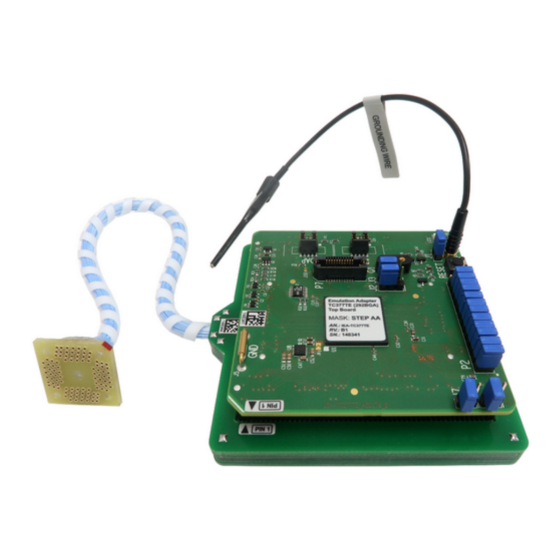
- Page 9 QFP Flex Adaptation – Flex PCB adapter This part provides a flexible connection of the Emulation Adapter to the Solder part as an alternative to the fixed connection. Refer to the chapter Assembly for more information about the assembly procedure. Flex PCB adapter Solder part BGA Adaptation...
-
Page 10: Measurement Board
Measurement board The Measurement board is an optional extension to the Emulation Adapter. Because embedded targets often do not have access to all the MCU pins / connected signals to connect with measurement equipment (oscilloscope, logic analyzer), its use provides easy access to all MCU pins respectively. -
Page 11: Operation
Operation How to connect? How to connect Emulation Adapter (Video Tutorial) How to connect iSYSTEM Hardware (Video Tutorial) Configuration J1: Target reset configuration Jumper J1 connects the Emulation Adapter reset line and the user target board reset line and is populated by default. The Emulation Adapter also features a Reset push button (SW1). - Page 12 Crystal socket Q1 schematics below: J4 & J5: GND connection points In case a good ground connection is required, connection points bridge J4 and pin J5 provide easy access to the Emulation Adapter's GND potential. J6 & J7: VFLEX & VAREF VFLEX - If the target’s VFLEX pin isn’t exposed, bridge the jumper J6 to connect VEXT from the target to power VFLEX.
- Page 13 VAREF - If the target’s VAREF2 pin isn’t exposed, bridge the jumper J7 to connect VAREF1 from the target to power VARE2 Setting the jumper if VAREF2 is present on the device may prevent establishing a debug connection or, in the worst case, can damage the Target board. P2: Power supply configuration EA Power supply is configured via the unshrouded 26-pin 2.54 mm header (P2).
-
Page 14: Connectors
Reset 10-pin Infineon DAP pinout Signal Direction is described from the BlueBox perspective. iSYSTEM BlueBox solution supporting Infineon DAP debug and trace interface connects to the P1 connector. P8: DAPE P8 connector exposes DAPE debug interface and has the following pinout:... -
Page 15: Standalone Operation
BlueBox solution supporting AGBT (Aurora GigaBit Trace) interface connects to the P7 connector. Standalone operation Infineon TC377TE Emulation Adapter is delivered with all components required for a Standalone operation. Power supply Use the enclosed IEA-PS Emulation Adapter Power converter and adapter. - Page 16 The Power converter can supply either 3.3 V or 5 V. The array of jumpers J0–J9 selects 3.3 V or 5 V voltage on the P3 connector, which connects to the Emulation Adapter. Signal Signal P3 connector and J0–J9 jumper correlation table For example, when J2 is in the 3V3 position, it supplies 3.3 V to pin 6 of the P3 connector.
-
Page 17: Mechanical Information
Mechanical information Emulation Adapter Side view of the Emulation adapter complete setup - QFP Fixed Adaptation Top view of the Emulation Adapter Top view of the Conversion board Unit (mm) Ordering code IEA-TC377TE-TOP 32.6 36.4 47.5 IEA-TC377TE-xxxxxx Solder parts Top view of the Solder part Solder part Solder pad view In the case of soldering the Solder part manually, it’s highly recommended to prolong the solder pad E on the outer side (e.g., for 1.5–2 mm) during the PCB design. - Page 18 Recommended PCB footprint dimensions: Unit (mm) Ordering code IANQPACK80SE 11.1 11.1 IANQPACK100SE 13.1 13.1 IANQPACK144SE 17.1 17.1 IA144TQ-SOLDER 19.5 19.5 0.25 1.625 25.05 25.05 IA176TQ-SOLDER 23.5 23.5 0.25 1.625 29.05 29.05 QFP Flex – Wire adapter QFP Flex – Wire adapter Unit (mm) Ordering code IEA-TC377TE-TC332W...
-
Page 19: Extenders
Extenders Side view of the Extender Top view of the Extender Unit (mm) Ordering code IA292LFBGA-EXTENDER 3.25... -
Page 20: Assembly
1. Solder the Solder part [B] on the embedded target PCB [A] to get a BA setup. Use the Surface Mount Technology (SMT) to solder the Solder parts to the user target board instead of the original microcontroller. iSYSTEM provides this soldering service on request too. - Page 21 Slot screw The Slot screw (30mm) can be used to fix the Conversion board (Fixed Adaptation) to the Solder part. This way the setup becomes mechanically more robust. Screw the Conversion board to the Solder part first, before the Emulation Adapter is attached on top and watch out not to break out the Solder part, e.g., if you accidentally hit the Emulation Adapter from the side.
-
Page 22: Qfp Flex
Connecting part [C] on the Solder part. You get a (C)BA setup. Use the Surface Mount Technology (SMT) to solder the Solder parts to the user target board instead of the original microcontroller. iSYSTEM provides this soldering service on request too. -
Page 23: Bga
1. Solder the Solder part [B] on the embedded target PCB [A] to get a BA setup. Use the Surface Mount Technology (SMT) to solder the Solder parts to the user target board instead of the original microcontroller. iSYSTEM provides this soldering service on request too. -
Page 25: Accessories
Accessories To ease the development process, we recommend using the following iSYSTEM hardware tools with the Infineon TC377TE Emulation Adapter. Ordering Code Description IC5700 iC5700 BlueBox On-Chip Analyzer IC5000 iC5000 BlueBox On-Chip Analyzer IC57031 IOM6 Hub (3 x FNet & FBridge) -
Page 26: Schematics
To view the Emulation Adapter schematics, click on the link below. Schematics To view the Emulation Adapter schematics: · Visit isystem.com/user-manuals, find your Emulation Adapter User Manual and go to the Schematics chapter, or · Scan the QR code below. -
Page 27: User Notes
User Notes This page is intentionally left blank. - Page 28 Whilst iSYSTEM reserves the right to make changes to its products and/or the specifications detailed herein, it does not make any representations or commitments to update this document.
Need help?
Do you have a question about the Infineon TC377TE and is the answer not in the manual?
Questions and answers