Table of Contents
Advertisement
Quick Links
Advertisement
Table of Contents

Related Manuals for Craftex CT174


Summary of Contents for Craftex CT174
- Page 1 CT174 6” x 48” BELT & 9” DISC SANDER User Manual...
-
Page 2: Table Of Contents
TABLE OF CONTENTS General Safety Instructions ................3 Specific Safety Instructions................4 CT174 Features....................5 Physical Features ..................6 Unpacking ....................7 Proper Grounding ..................7 Installing the Sanding Disc ................8 Installing the Sanding Belt ................8 Belt Tracking Adjustment................9 Installing the Dust Ports................10 Installing the Work Table ................10 Installing the Back Stop ................11... -
Page 3: General Safety Instructions
GENERAL SAFETY INSTRUCTIONS Extreme caution should be used when operating all power tools. Know your power tool, be familiar with its operation, read through the owner’s manual and practice safe usage procedures at all times. ALWAYS read and understand the router bits, shaper heads, blades, user manual before operating the knives or making other adjustments or... -
Page 4: Specific Safety Instructions
CT174 sander, before operating it. DO NOT force the sander. It will do the If you fail to do so, serious injury could job better and will be safer at the occur. -
Page 5: Ct174 Features
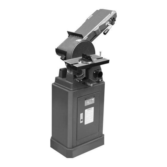
MODEL CT174 – 6” x 48” BELT & 9” DISC SANDER As part of the growing line of Craftex woodworking equipment, we are proud to offer the CT174 a 6” x 48” Belt and 9” Disc Sander. The Craftex name guarantees Craft Excellence. By following the instructions and procedures laid out in this user manual, you will receive years of excellent service and satisfaction. -
Page 6: Physical Features
CT174 – 6” x 48” Belt & 9” Disc Sander PHYSICAL FEATURES 6” x 48” Belt Guard Cover Sanding Belt Lock Knob Backstop Quick Release Tension Lever 9” Sanding Disc Table Stop Bolt 2.5” Dust Port Work Table Table Tilt... -
Page 7: Unpacking
Open the crate and check that the machine is in good condition. WARNING CT174 is a heavy machine, do not over- exert yourself. Use fork truck or other Figure-1 120-Volts Outlet for CT174 mechanical devices for safe moving. -
Page 8: Installing The Sanding Disc
INSTALLING THE sanding disc cover shown in figure-2. SANDING BELT The CT174 comes with a 6” x 48” sanding belt. To install the sanding belt: Make sure the switch is in the OFF position and the cord is disconnected from the power source. -
Page 9: Belt Tracking Adjustment
When the belt is centered and tracking centered on both the rollers. properly on the rollers, stop the sander and re-install the safety guards, backstop and Your CT174 sander is shipped with the belt the dust port removed previously. tracking mechanism properly adjusted. -
Page 10: Installing The Dust Ports
the rod is facing the two set screws. Then INSTALLING THE DUST tighten the two set screws. See figure-9. PORTS Install the dust ports to the back of the sanding belt frame and the sanding disc cover using the pre-installed screws and washers. -
Page 11: Installing The Back Stop
INSTALLING THE BACK ON/OFF SWITCH STOP CT174 is equipped with a rocker-type power switch which starts and stops the When the sanding belt is set for horizontal motor and is located on sanding disc side sanding, the backstop should be used to on the base of the sander. -
Page 12: Test Run
TEST RUN WORK-PIECE INSPECTION Once you have assembled your machine CT174 is designed to sand wood only. Do completely, it is then time for a test run to not use this machine to sand metals, glass make sure that the machine works properly or stone etc. -
Page 13: Adjusting The Work Table Tilt
must be sanded on the roller portion of the sanding belt. WARNING The fine dust particles produced by the Make sure to move the work-piece equally woodworking machines can go inside along the sanding belt and use the miter your lungs and cause serious respiratory gauge for precise work. -
Page 14: Adjusting The Miter Gauge
Re-tighten the lock nuts securing the belt ADJUSTING THE MITER sander in position. GAUGE To position the belt sander horizontally, The miter gauge is used to hold and lower the belt sander completely until it sits support the work-piece at a desired angle on the stop bolt shown in figure-17. -
Page 15: Maintenance
MAINTENANCE V-BELT TENSION & REPLACEMENT During the lifetime of your machine, you will need to practice some regular maintenance The V-belt is pre-installed and tension at to keep your saw in peak performance the factory. It stretches with use and should condition. - Page 16 Figure-21 Motor mounting lock nuts Figure-22 Correct belt tension At this point the V-belt should be loose enough to slip it off the pulleys. If the deflection is not approximately 1/4" when you push with moderate pressure, Replace the V-belt with a new one and loosen the motor mounting nuts and re- install it on the pulleys.
-
Page 17: Troubleshooting
TROUBLESHOOTING... -
Page 20: Warranty
This warranty shall not apply to consumable products such as blades, bits, belts, cutters, chisels, punches etceteras. Craftex shall in no event be liable for injuries, accidental or otherwise, death to persons or damage to property or for incidental contingent, special or consequential damages arising from the use of our products.
Need help?
Do you have a question about the CT174 and is the answer not in the manual?
Questions and answers