
Related Manuals for Stryker Visum 300


Summary of Contents for Stryker Visum 300
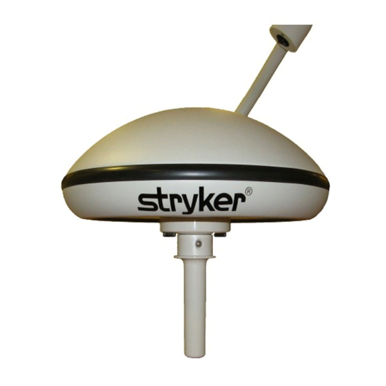
- Page 1 Stryker Visum 300® Ceiling-Mounted Exam Light Assembly, Operations, and Maintenance Manual...
-
Page 3: Table Of Contents
Light Does Not Function ..........................27 8. Technical Specifications ..........................28 Environmental Specifications ........................28 Electrical Specifications ...........................28 Lighting Data ...............................28 Physical Data ................................28 9. Maintenance..............................29 10. Product Disposal ............................30 11. Damage Claims ...............................30 12. Stryker Limited Warranty ..........................30 13. Contact Information ............................31... -
Page 4: Indications For Use
1. Indications for Use The intended use of the Stryker VISUM® Lighting system is to illuminate the patient’s surroundings, as well as the body of the patient to support diagnosis and treatment. It has not been designed as a surgical light, or for use by the patient. -
Page 5: Warnings And Cautions
3. Follow the care and cleaning instructions in this manual. 4. Adjustments, modifications, and/or repairs not described in this manual should be performed only by Stryker personnel. 5. The electrical installation of the operating room must comply with any applicable IEC, CEC, NEC... -
Page 6: Product Symbol Definition
3. Product Symbol Definition The following symbols may be found on the Stryker VISUM® 300 Ceiling-Mounted Exam Light: An exclamation mark within a triangle is intended to alert the user to the presence of important operating and maintenance (service) instructions in the literature accompanying the product. -
Page 7: Visum® 300 Components
4. VISUM® 300 Components Figure 1 - VISUM® 300 Components Sheet Metal Guard Elbow Down Tube Flange Spring Arm Sheet Metal Enclosure Power Switch Ceiling Cover Light Head Down Tube Light Handle Assembly Extension Arm REVISIONS REV. DESCRIPTION DATE CHECK APPROVED Figure 2 - VISUM®... -
Page 8: Installation
5. Installation Warning • The light should be installed down circuit from a circuit breaker, or should be installed with a switch to turn the main power off. • Make sure that the power to the installation site is off during all installation procedures. Refer to the VISUM®... - Page 9 Super Structure Customer Provided 3-8” FALSE CEILING Access Panel Down Tube Flange with Ceiling Ceiling Cover Figure 4 - Down Tube, Super Structure, and False Ceiling Down Tube Height + .25” 110mm 1” 220-800mm 1”-2” Bottom of False Ceiling Figure 5 - Down Tube Assembly Preparation Spring Washer Flat Washer Upper Nut...
- Page 10 Figure 6 - Detail of Installation Without Ceiling Cover Access Panel Transformer Clamping Nut and Washer Junction Box 10. Ceiling Structure Conduit and Fitting 11. Threaded Rod (Customer Supplied) Conduit Fitting Nut 12. False Ceiling (Customer Supplied Transformer Mounting 13. Sheet Metal Guard Screw Transformer Insulating 14.
- Page 11 Figure 7 - Bolt, Nut, and Washer Installation Conduit Fitting False Ceiling (Customer Supplied) Down Tube Flange Lower Flat Washer Sheet Metal Guard Lower Nut Upper Nut Spring Washer Upper Flat Washer 10. Sheet Metal Enclosure (Customer Supplied) 11. Conduit Fitting Nut (Customer Supplied)
-
Page 12: Installing The Extension Arm With The Spring Arm
Installing the Extension Arm with the Spring Arm Perform the following steps to install the extension arm with the spring arm. Refer to Figure 8 as needed. 1. Unscrew the Phillips-head screw. 2. Remove and discard the protective cover installed on the down tube axle (not shown in Figure 8). - Page 13 Caution Do not attempt to push the spring arm beyond its stop(s). Doing so will cause damage to the spring arm. 3. Remove and discard the protective cap on the spring arm. 4. Install the brake cover over the spring arm so that the keeper clip slots in the spring arm and brake cover are aligned.
-
Page 14: Operations
6. Operations Turning the Light On and Off The switch for turning the light on and off is located at the end of the light head, as shown in Figure 10. The “On” setting is indicated on the switch by a “1”; the “Off” setting is indicated by a “0”. Figure 10 - Light On/Off Switch Positioning the Light Head/Suspension Warning... - Page 15 PROPRIETARY AND CONFIDENTIAL TOLERANCING PER: COMMENTS: THE INFORMATION CONTAINED IN THIS SIZE MATERIAL DWG. NO. Visum 300 Install Assembly DRAWING IS THE SOLE PROPERTY OF <INSERT COMPANY NAME HERE>. ANY FINISH REPRODUCTION IN PART OR AS A WHOLE UNLESS OTHERWISE SPECIFIED: NAME...
-
Page 16: Cleaning And Disinfecting The Sterilizable Light Handle Cover
Cleaning and Disinfecting the Sterilizable Light Handle Cover Cautions • The button is not sterilizable. • Power off system before cleaning. Make sure that no cleaning fluid enters the system. • To avoid damage to plastic parts, do not use any scouring, alkaline, acidic, or alcohol-based cleaning agents. -
Page 17: Replacing The Halogen Bulb
Replacing the Halogen Bulb Perform the following steps to replace the halogen bulb. Warning Allow the light to cool before attempting maintenance. Caution Do not touch the halogen bulb directly; instead, grasp the reflector. 1. After the light has been turned off and allowed to cool, remove the optional sterile handle if necessary. - Page 18 6. Remove the bulb from porcelain bulb holder. 7. Insert the new bulb holder and tighten the two screws 8. Insert the replacement bulb into the socket of the porcelain bulb holder. Light Handle Light Head 9. Replace the handle assembly. Guide the banana clips into the Side Side power receptacles, ensuring that the handle assembly is seated...
-
Page 19: Replacing Fuses
Replacing Fuses Warning Turn off the light and disconnect power from the unit before changing the fuses. Perform the following steps to replace fuses. 1. Remove the ceiling cover by unscrewing the three set screws and then sliding the cover down the down tube, as shown in the picture to the right. -
Page 20: Replacing The Transformer
1. Remove the light head and spring arm assembly according to the “Removing the Light Head” and “Removing the Extension Arm with the Spring Arm” procedures in the Stryker VISUM® 300 Ceiling- Mounted Exam Light Installation, Operations, and Maintenance Manual. - Page 21 12. Reinstall the sheet metal enclosure and the ceiling cover. 13. Reinstall the extension arm and light head according to the “Installing the Extension Arm with the Spring Arm” and “Attaching the Light Head” procedures in the Stryker VISUM® 300 Ceiling-Mounted Exam Light Installation, Operations, and Maintenance Manual.
-
Page 22: Replacing The Aesthetic Covers
Primary 230 V Primary 115 V Secondary 14 V Secondary 14 V Figure 14 - Transformer Wiring Diagram Figure 13 - Transformer Wiring Diagram (230V Model) (115V Model) Replacing the Aesthetic Covers Warning Disconnect power from the unit before replacing the aesthetic covers. Perform the following steps to replace the aesthetic covers. - Page 23 3. Slide the covers away from the suspension. 4. If the elbow cup collar needs to be replaced, first remove the light head according to the “Removing the Light Head” Grounding Screw procedure in this manual, then remove the grounding screw and the brake cover from the end of the spring arm so that you can slide the elbow cap collar completely off.
-
Page 24: Removing The Light Head
Removing the Light Head Warning • Make sure that the light is turned off and power is disconnected from the suspension before performing this procedure. • The spring arm is under high spring tension. If the arm is not in its highest position, when this operation is performed, it may jump suddenly, causing injury. -
Page 25: Removing The Down Tube Assembly
6.11 Removing the Down Tube Assembly Warning Disconnect power from the unit before removing the down tube assembly. After you have removed the extension arm with the spring arm, it may also be necessary to remove the down tube assembly for maintenance. Perform the following steps to do so (refer to Figures 4, 5, and 6 as needed). - Page 26 2. Pull the light head down 20° to expose the spring adjustment hole and screw in the elbow. 3. Insert a flathead screwdriver into the spring adjustment hole (indicated in the picture to the right), then let go of the spring arm.
-
Page 27: Troubleshooting
Halogen bulb needs to be replaced Replace the light’s halogen bulb Loose connections Check all terminal connections in the light fixture Note If any of these issues cannot be resolved, please contact Technical Support or your Stryker representative. AC MAIN 115V Circuit... -
Page 28: Technical Specifications
8. Technical Specifications Environmental Specifications Operating Humidity: 30%-75% Storage Humidity 10%–75% Operating Temperature 10–40 °C Storage Temperature 10–40 °C Electrical Specifications Rated Input Voltage 115 V Nominal Frequency 60 Hz Output Current at 14 V (at light) 4.3 A Max Power Delivered by the 115 V Version 50 W Lighting Data Central Illumination... -
Page 29: Maintenance
• Fully seated C-clips Caution Use only Stryker-provided parts. Note: Service schedules, circuit diagrams, spare parts lists, descriptions, adjustment instructions, and other documents can be made available if desired. In case of any faults or damage, or for service, contact Stryker Communications. -
Page 30: Product Disposal
Stryker subsidiary. Stryker warrants that its products shall be free of defects of material and workmanship for a period of two years after date of shipment. Stryker will provide all parts and service required to restore equipment under warranty to good working condition, which may include shipment of replacement parts and phone service consultation to conduct minor repairs. -
Page 31: Contact Information
13. Contact Information Contact Stryker Customer Service with questions or concerns. Stryker Communications 571 Silveron Blvd. Flower, Mound, TX 75028 Toll Free: (866) 841-5663 1-972-410-7100 For international service locations, refer to the Stryker website at the following URL: www.stryker.com. - Page 32 Stryker Corporation or its divisions or other corporate affiliated entities own, use or have applied for the following trademarks or service marks: the Stryker logo. All other trademarks are trademarks of their respective owners or holders. *1004400184J* 2017/01 *1004400184J*...
Need help?
Do you have a question about the Visum 300 and is the answer not in the manual?
Questions and answers