Sign In
Upload
Download
Table of Contents
Contents
Add to my manuals
Delete from my manuals
Share
URL of this page:
HTML Link:
Bookmark this page
Add
Manual will be automatically added to "My Manuals"
Print this page
×
Bookmark added
×
Added to my manuals
Manuals
Brands
Stryker Manuals
Medical Equipment
Visum 600
Installation and service manual
Stryker Visum 600 Installation And Service Manual
Hide thumbs
1
2
3
4
Table Of Contents
5
6
7
8
9
10
11
12
13
14
15
16
17
18
19
20
21
22
23
24
25
26
27
28
29
30
31
32
33
34
35
36
37
38
39
40
41
42
43
44
45
46
47
48
49
50
51
52
53
54
55
56
57
58
59
60
61
62
63
64
65
66
67
68
69
70
71
72
73
74
75
76
77
78
79
80
81
82
83
84
85
86
87
88
89
90
91
92
93
94
95
96
97
98
99
100
101
102
103
104
105
106
107
108
109
110
111
112
113
114
115
116
117
118
119
120
121
122
123
124
125
126
127
128
129
130
131
132
133
134
135
136
137
138
139
140
141
142
143
144
145
146
147
148
149
page
of
149
Go
/
149
Contents
Table of Contents
Troubleshooting
Bookmarks
Table of Contents
Table of Contents
1 Warnings and Cautions
Safeguards and Precautions
Warnings
2 Product Symbol Definition
3 Tool List
Required Tools
Optional Tools
4 Unpacking
Halogen Light
Suspension Box
Accessory Box
Light Head Boxes
LED Light
Suspension Box
Accessory Box
Light Head Boxes 1 and 2
Flat Panel Arms
Booms
5 Preparing the Mounting (Interface) Plate
6 Preparing the Suspensions
Installing the Cable Kit for Lights
Surgical Lights
Standard Horizontal Arm
Extended Horizontal Arm
Alternate Light Installation Instructions
Flat Panel
Booms
Routing Cables
7 Installing the Suspension and Boom Arms
Alternate Light Installation Instructions (Continued)
8 Installing Light Heads
LED and Halogen
Standard Light
Low Ceiling Light
9 Powering the System
Halogen Lights
Electrical and Data Connections
LED Lights
Power Supply Box Wall Mount (Optional)
Power Supply Box Connections
Power
Control
Wall Control Unit Port
Sorn
Sidne
Expansion Port (Optional)
Visum LED New Installation Setup
Required Tools
Installing USB to RS-232 Adapter (for Laptops Without Serial Ports)
Connecting a Laptop to the SIDNE Port on Visum LED System
Visum LED Main Menu
New Installation
10 Monitor Assembly
Light Flat Panel or Single Panel Installation
Adjusting the Yoke
Adjusting the Width
Adjusting the Height
Attaching the Monitor
Balancing the Monitor
Adjusting the Brakes
11 Boom Shelf Attachment and Adjusting Brakes/Stops
Boom Shelf and Accessories Attachment
Flexis Shelf Installation
Flexis Handle to MFR Bracket Installation
Flexis Handle to Service Head Installation
Installing Auxiliary Plates
Installing Other Accessories
Installing GCX Accessory Track on OSC600 down Tube
Drawer Installation
Lights and Flat Panel Arms
Height Adjustment
Tension Adjustment
Adjusting the Friction Brakes
Adjusting the Brake Force of the Extension and Spring Arms
Adjusting down Tube Screws
Adjusting the Cardanic Suspension
Boom Arms
Osc400
Osc600
12 Installing Covers
Lights and Flat Panel Suspension
Booms
Tandem
Cable Covers
Flat Panel/Light/Light Suspension
Light/Flat Panel Suspension - Teacup Installation
MMP200, OSC400, and OSC600
Mounting Motor Ring Covers
Replacing Rear End Spring Arm Covers
Installing a Flexstrip Kit (Dual Flat Panel Arm Only)
13 Accessories
Lights
Halogen In-Light Camera and Weighted Light Handle Assemblies
LED In-Light Camera and Weighted Light Handle Assemblies
Field Upgrade for Strykecam In-Light Camera
Power Supply Box Components
Camera Installation
14 Legacy
Suspension Installation
Installing Spring Arms (if Necessary for Lights Only Suspension)
Standard Width Yoke
Halogen Light Flat Panel Stop Replacement
Variant
Installing GCX Accessory Track on OSC400 Service Head
15 Cleaning and Completion
16 Servicing the Visum 600/450
Electronic Control System
Power Supply Box
Halogen Power Supply Box Troubleshooting Guide
Wall Control
Plug Layout of the Electronic Control System
Plug Allocation
Location of the Plug and Diagnostic Leds on the Terminal
Plug Allocation Operating Console and Diagnostic Leds
Plug Locations of the Power Box
Connections at the Front
Connections at the Back
Connection Structure of Systems
Can Bus Troubleshooting
Light Block Diagram
17 Servicing Booms
System Operation
Troubleshooting
Air Leaks
Miscellaneous Hardware Parts List
Replacing the Trim Strip
Replacing Med Gas
Replacing a Nitrogen Regulator
Replacing Med Gas Plate
Replacing the Brake Bladder
Reassembling the Service Head
Removing and Attaching the Front and Back Plates
Removing and Attaching the MFR
Removing Extrusions
Installing Extrusions
Removing Modules
Installing Modules
Replacing the Motor
Electro-Pneumatic (EP) Module
Removing the Electro-Pneumatic (EP) Module
Installing an Electro-Pneumatic (EP) Module
Generation 1 Service Head
Replacing a Shelf with Brake
Replacing the Brake Button
18 Servicing the LED
19 Replacement Part Numbers
20 Contact Information
Advertisement
Quick Links
1
Replacement Part Numbers
Download this manual
ALL OR'S SHOULD BE CONSIDERED AS
Booms and Lights
FULLY INTEGRATED WITH VIDEO, VOICE
ACTIVATION AND INSTRUMENT CONTROL
Installation and Service Manual
July 2011
1004-400-061 REV YB
www.stryker.com
Table of
Contents
Previous
Page
Next
Page
1
2
3
4
5
Advertisement
Table of Contents
Troubleshooting
Power Supply Box
96
Can Bus Troubleshooting
110
Servicing Booms
114
Need help?
Do you have a question about the Visum 600 and is the answer not in the manual?
Ask a question
Questions and answers
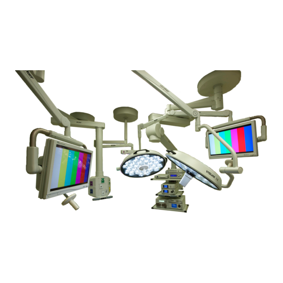
Related Manuals for Stryker Visum 600
Medical Equipment Stryker Visum Operation Manual
Blade led surgical light system (44 pages)
Medical Equipment Stryker Visum 300 Assembly, Operation And Maintenance Instructions
Ceiling-mounted exam light (32 pages)
Medical Equipment Stryker Visum 450 Installation And Service Manual
(149 pages)
Medical Equipment Stryker B3000n Badge Cleaning Manual
(6 pages)
Medical Equipment Stryker Flyte 0408-600-000 Instructions For Use Manual
Surgical helmets (120 pages)
Medical Equipment Stryker Prime Series Operation Manual
Stretcher (1244 pages)
Medical Equipment Stryker CUB FL19F Maintenance Manual
Pediatric crib (284 pages)
Medical Equipment Stryker Power-PRO 2 Operation & Maintenance Manual
Ambulance cot (76 pages)
Medical Equipment Stryker 3000 Maintenance Manual
Modular patient system mps bed (249 pages)
Medical Equipment Stryker 4701 Operation Manual
Birthing bed (31 pages)
Medical Equipment Stryker SDC3 Manual
Hd information management system powershare package (100 pages)
Medical Equipment Stryker LD304 Operation Manual
Birthing bed (28 pages)
Medical Equipment Stryker Prime TC 1450 Operation & Maintenance Manual
Transport chair (98 pages)
Medical Equipment Stryker SV2 Operation Manual
Electric hospital bed (1067 pages)
Medical Equipment Stryker L10 Instructions For United States Users
Led light source with aim technology (52 pages)
Medical Equipment Stryker InTouch FL27 Maintenance Manual
(252 pages)
Summarization of Contents
Warnings and Cautions
Safeguards and Precautions
Information on authorized personnel, safety measures, and equipment handling.
Warnings
Guidelines for qualified installers, electrical safety, and unpacking precautions.
Product Symbol Definition
Tool List
Required Tools
Lists essential tools for installation and service.
Optional Tools
Lists recommended tools for specific tasks.
Unpacking
Halogen Light
Details on unpacking components of the halogen light system.
LED Light
Instructions for unpacking components of the LED light system.
Flat Panel Arms
Information on unpacking the flat panel arm system components.
Booms
Instructions on unpacking boom arm components.
Preparing the Mounting (Interface) Plate
Preparing the Suspensions
Installing the Cable Kit for Lights
Procedures for routing and connecting power and control cables.
Surgical Lights
Installation procedures for surgical light arms.
Flat Panel
Installation steps for the flat panel component.
Booms
Assembly instructions for boom components before installation.
Routing Cables
Guidance on properly routing system cables.
Installing the Suspension and Boom Arms
Alternate Light Installation Instructions (Continued)
Continuation of alternative methods for installing light systems.
Installing Light Heads
LED and Halogen
Procedures for installing LED and halogen light heads onto arms.
Standard Light
Detailed steps for installing standard light heads.
Low Ceiling Light
Detailed steps for installing low ceiling light heads.
Powering the System
Halogen Lights
Procedures for powering and connecting halogen light systems.
LED Lights
Procedures for powering and connecting LED light systems.
Power Supply Box Connections
Details on connecting various ports on the power supply box.
Visum LED New Installation Setup
Setup process for new Visum LED installations via laptop.
Monitor Assembly
Light Flat Panel or Single Panel installation
Steps for installing light flat panel or single panel monitors.
Adjusting the Yoke
Procedures for adjusting the monitor yoke's width and height.
Attaching the Monitor
Steps for securely attaching the monitor to the yoke assembly.
Balancing the Monitor
Process for balancing the monitor and ensuring smooth movement.
Adjusting the Brakes
Instructions for adjusting the brakes to hold the monitor position.
Boom Shelf Attachment and Adjusting Brakes/Stops
Boom Shelf and Accessories Attachment
Procedures for attaching boom shelves and accessories.
Lights and Flat Panel Arms
Adjustments for height, tension, and brakes on lights and flat panel arms.
Adjusting the Cardanic Suspension
How to adjust the Cardanic suspension brakes.
Boom Arms
Specific adjustments for OSC400 and OSC600 boom arms.
Installing Covers
Lights and Flat Panel Suspension
Installing covers for light and flat panel suspension systems.
Booms
Installing covers for various boom components.
Tandem
Installation procedures for tandem boom covers.
Cable Covers
Guidance on installing cable covers for different arm types.
Installing a Flexstrip Kit (Dual Flat Panel Arm Only)
Steps for installing a flexstrip kit on dual flat panel arms.
Accessories
Lights
Accessories related to light heads, including cameras and handles.
Power Supply Box Components
Details on the components within the power supply box.
Camera Installation
Steps for installing the camera into the light head assembly.
Legacy
Suspension Installation
Steps for installing legacy suspension systems.
Installing Spring Arms (if necessary for lights only suspension)
Instructions for installing spring arms for light-only suspensions.
Standard Width Yoke
Installation and adjustment procedures for a standard width yoke.
Halogen Light Flat Panel Stop Replacement
Procedure for replacing flat panel stops on halogen lights.
Variant
Installation of variant end caps on extension arms.
Installing GCX Accessory Track on OSC400 Service Head
Steps for installing GCX accessory track onto the OSC400 service head.
Cleaning and Completion
Servicing the Visum 600/450
Electronic Control System
Overview of the electronic control system's functions and components.
Power Supply Box
Details on the power supply box, its components, and troubleshooting.
Wall Control
Description of the wall control unit's interface and functions.
Plug Layout of the Electronic Control System
Diagram showing plug-in connections on the electronic control system.
Plug Allocation
Details on plug connections and their pin assignments.
Can Bus Troubleshooting
Troubleshooting steps for CAN bus communication issues.
Servicing Booms
System operation
Overview of the EDS Boom System's pneumatic braking system.
Troubleshooting
Common troubleshooting categories for boom systems, including air leaks.
Miscellaneous Hardware Parts List
A list of various hardware parts used in boom assembly.
Replacing the Trim Strip
Steps for replacing the trim strip on the boom arm.
Replacing Med Gas
Procedures for replacing nitrogen regulators and med gas plates.
Replacing the Brake Bladder
Steps for replacing the brake bladder in an OSC400 boom.
Reassembling the Service Head
Procedures for removing, attaching, and installing service head components.
Replacing the Motor
Steps for replacing the motor assembly in the boom system.
Electro-Pneumatic (EP) Module
Procedures for removing and installing the EP module.
Generation 1 Service Head
Procedures for replacing shelves with brakes and brake buttons.
Servicing the LED
Replacement Part Numbers
Contact Information
Table of Contents
Save PDF
Print
Rename the bookmark
Delete bookmark?
Delete from my manuals?
Login
Sign In
OR
Sign in with Facebook
Sign in with Google
Upload manual
Upload from disk
Upload from URL
Need help?
Do you have a question about the Visum 600 and is the answer not in the manual?
Questions and answers