Stryker S3 Operation Manual
Medical surgery bed with stayput frame
Hide thumbs
Also See for S3:
- Operation manual (78 pages) ,
- Quick start manual (28 pages) ,
- Operation manual (72 pages)

Subscribe to Our Youtube Channel
Related Manuals for Stryker S3


Summary of Contents for Stryker S3
- Page 1 S3® MedSurg Bed with StayPut® Frame Battery Backup / Zoom® 3002 Operations Manual 2016/11 B.1 3006-209-001 REV B www.stryker.com...
- Page 2 sample text...
- Page 3 Symbols Operating instructions/Consult instructions for use General warning Caution Catalogue number Serial number For US Patents see www.stryker.com/patents Manufacturer Safe working load Dangerous voltage Alternating current Direct current Unit provides terminal for connection of a potential equalization conductor. The potential equalization conductor provides direct connection between the unit and potential equalization busbar of the electrical installation.
- Page 4 Symbols Caution; electrostatic sensitive iBed Locator is connected iBed Locator is not connected Network is connected Network is not connected This device complies with Part 15 of the FCC rules 3006-209-001 REV B www.stryker.com...
-
Page 5: Table Of Contents
Specifications.............................8 System requirements and recommendations for iBed Wireless (option) ............9 iBed Server requirements for iBed Wireless (option) ................9 Stryker iBed Wireless Client radio specifications................10 Client device data usage....................... 11 Customer network communication requirements for iBed Wireless option ..........12 Product illustration.......................... - Page 6 Cleaning..............................65 Disinfecting............................66 Preventive maintenance ........................... 67 FCC notification ............................69 EMC information ............................. 70 Warranty ............................... 74 Warranty exclusion and damage limitations .................... 74 To obtain parts and service ......................... 74 Return authorization........................... 74 3006-209-001 REV B www.stryker.com...
- Page 7 Table of Contents Damaged product..........................74 International warranty clause ....................... 74 www.stryker.com 3006-209-001 REV B...
-
Page 8: Warning/Caution/Note Definition
Note: Provides special information to make maintenance easier or important instructions clearer. 3006-209-001 REV B www.stryker.com... -
Page 9: Summary Of Safety Precautions
This product is equipped with a hospital-grade plug for protection against electric shock hazard. • Always use a Stryker supplied interface cable. Use of any other cable may cause the bed to function improperly, which may result in patient or user injury. •... - Page 10 Always determine the proper use of the restraint straps and restraint strap locations. Improperly adjusted restraint straps can cause serious injury to a patient. Stryker is not responsible for the type or use of restraint straps on any Stryker products.
-
Page 11: Introduction
If you have any questions, contact Stryker Customer Service or Technical Support at 1-800-327-0770. Product description The 3002 S3® ® MedSurg Bed has fowler, gatch and lift articulation capabilities that aide in the adjustment of surface contour, angle, and height. The product offers various options outlined in the product operations manual, including but not limited to iBed®... -
Page 12: Expected Service Life
Introduction Expected service life The 3002 S3 MedSurg bed has a ten year expected service life under normal use conditions and with appropriate periodic maintenance. The optional motion/nurse call pendant has a two year expected service life under normal use conditions. -
Page 13: System Requirements And Recommendations For Ibed Wireless (Option)
80 lb 36.3 Note: These mattress specifications comply with HBSW and IEC specifications. Stryker reserves the right to change specifications without notice. Specifications listed are approximate and may vary slightly from product to product or by power supply fluctuations. Operation... -
Page 14: Stryker Ibed Wireless Client Radio Specifications
Provide remote access to the iBed Server machines. For example, VPN, Citrix Note: Backups of the system or a Disaster Recovery Plan is the responsibility of the customer. Stryker iBed Wireless Client radio specifications Manufacturer model Silex SX-SDMAN-2830S Chipset AR6233X, Core chip AR6003X CSP (Qualcomm Atheros) 3006-209-001 REV B www.stryker.com... -
Page 15: Client Device Data Usage
2.4 GHz: All Channels Supported 5 GHz: All Channels Supported (Recommend against using DFS and ISM Channels) Other Stryker iBed Wireless Client is able to connect to an existing SSID Client device data usage • The client uses 10-15 KB per connected device every 40 seconds. -
Page 16: Customer Network Communication Requirements For Ibed Wireless Option
Source Protocol / Port number Destination iBed Server TCP/21 Stryker iBed Wireless Client iBed Server TCP/80/443 Third party / Stryker back office iBed Server TCP/1639 Stryker iBed Wireless Client Third party / Stryker iBed Wireless TCP/80/443 iBed Server Client Customer WLAN environment... - Page 17 Stryker Wireless Client device (~6 mW 2.4 GHz or 12 mW 5 GHz). The received signal strength indicator (RSSI) of the Stryker iBed Wireless Client on the AP must be verified. The device should never drop below an RSSI of -75 dBm on the AP.
-
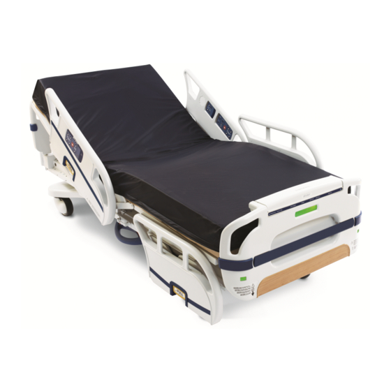
Page 18: Product Illustration
Patient control panel Footboard BackSmart footboard control panel Siderail release handle Headboard BackSmart siderails iBed Awareness LED light bar BackSmart steer pedal Integrated pump rack Support surface Contact information Contact Stryker Customer Service or Technical Support at: 1-800-327-0770. 3006-209-001 REV B www.stryker.com... -
Page 19: Serial Number Location
Portage, MI 49002 To view your operations or maintenance manual online, see https://techweb.stryker.com/. Have the serial number (A) of your Stryker product available when calling Stryker Customer Service or Technical Support. Include the serial number in all written communication. Serial number location... -
Page 20: Setup
Equipping the optional nurse call communication WARNING Always use a Stryker supplied interface cable. Use of any other cable may cause the bed to function improperly, which may result in patient or user injury. If your product is equipped with the optional nurse call communication, follow the setup instructions below before putting the product into service. -
Page 21: Setting Up The Optional Zoom
4. With the battery power switch on and the drive wheel in the neutral position, make sure that the Engage drive wheel LED illuminates on the head end control panel (Zoom motorized drive panel (option) on page 59). www.stryker.com 3006-209-001 REV B... -
Page 22: Setting Up The Optional Ibed Wireless
(Transporting the product with the Zoom motorized drive (option) on page 20) to make sure that each function is working. Contact Stryker Technical Support at (800) 327-0770 with any setup questions. Setting up the optional iBed Wireless WARNING Always associate or map the iBed Locator to the room or location to provide accurate location information. Failure to properly associate or map the iBed Locator to the room or location will yield incorrect remote information. -
Page 23: Applying Or Releasing The Brakes
(Figure 5 on page 20). To release steer lock, push the steer lock pedal to off (Figure 5 on page 20). Note: To move the product in any direction, including laterally, release the steer lock pedal. www.stryker.com 3006-209-001 REV B... -
Page 24: Transporting The Product With The Zoom Motorized Drive (Option)
To transport with the Zoom motorized drive: Unplug the power cord from the wall outlet and secure the cord. Note: The motorized drive wheel will not operate if the power cord is plugged into the wall outlet. 3006-209-001 REV B www.stryker.com... - Page 25 To place the motorized drive wheel in the neutral position, push the drive wheel pedal to neutral (Figure 7 on page 21). Figure 7: Drive / neutral Release the brakes. Note: The motorized drive wheel will not function while the brakes are applied. www.stryker.com 3006-209-001 REV B...
-
Page 26: Charging The Battery (Option)
The Plug bed in to charge LED illuminates while the battery power switch is on and the battery level is low (Battery backup panel (option) on page 58). To charge the battery: Plug the power cord into a wall outlet. 3006-209-001 REV B www.stryker.com... -
Page 27: Activating The Cpr Release
You can find the two CPR release levers at the head end section on both the left and right sides of the Fowler (A) (Figure 9 on page 23). To activate the CPR release: Grasp and squeeze the lever on either side of the Fowler. Guide the Fowler to the flat position. Figure 9: Activating the CPR release www.stryker.com 3006-209-001 REV B... -
Page 28: Raising The Lower Leg Section
Guide the foot prop down into the litter (B) (Figure 10 on page 24). Attaching a fracture frame WARNING Use only retractable traction or fracture frames. Failure to use a retractable frame may result in injury to the patient and/or damage to the equipment. 3006-209-001 REV B www.stryker.com... -
Page 29: Securing A Foley Bag To The Foley Bag Hooks
Always determine the proper use of the restraint straps and restraint strap locations. Improperly adjusted restraint straps can cause serious injury to a patient. Stryker is not responsible for the type or use of restraint straps on any Stryker products. -
Page 30: Raising The Siderails
To raise the siderail to its highest position, grasp the release handle and rotate the siderail toward the head end of the product (Figure 14 on page 27). Note: The siderail does not lock into the intermediate position when you raise the siderail. 3006-209-001 REV B www.stryker.com... -
Page 31: Lowering The Siderails
Make sure that the siderail is in the lowest position before you raise the siderail directly to the full up position. If you do not completely lower the siderail, the siderail will lock into the intermediate position when you raise the siderail. www.stryker.com 3006-209-001 REV B... -
Page 32: Positioning The Optional Two-Stage Permanently Attached Iv Pole
29). To lower the pole, turn the latch (C) clockwise until the telescoping portion (A) lowers into the bottom tube (Figure 17 on page 29). Lift up and pivot the pole down into the storage position. 3006-209-001 REV B www.stryker.com... -
Page 33: Positioning The Optional Removable Iv Pole
To raise the height of the pole, turn the knob (A) counterclockwise and pull up on the telescoping portion (B) of the pole (Figure 18 on page 30). Turn the knob (A) clockwise to tighten the telescoping portion (B) in place (Figure 18 on page 30). www.stryker.com 3006-209-001 REV B... -
Page 34: Illuminating The Room With The Night Light
To activate nurse call, press the Nurse call button (E) (see Operator control panel (outside siderail) on page 34). Communication between the patient and the nurse station is established at the moment when the nursing staff responds to the nurse call signal. 3006-209-001 REV B www.stryker.com... -
Page 35: Replacing The Nurse Call Backup Battery (Option)
If the switch is not positioned as shown below (A) (Figure 21 on page 32) and the bed power cord and pendant cord are unplugged, the life of the backup battery will be significantly reduced. www.stryker.com 3006-209-001 REV B... - Page 36 Separate the Velcro that holds the battery housing (B) to the litter frame and lift the battery housing until it is free from the litter frame (Figure 22 on page 32). Discard the battery. Note: Follow local regulations for disposal or recycling of this part. Reverse steps to reinstall. 3006-209-001 REV B www.stryker.com...
-
Page 37: Connecting Peripheral Equipment To The Built-In 110 Volt Auxiliary Power Outlet (Option)
The 110 volt auxiliary power outlet is a built-in outlet for peripheral equipment. You can find the outlet under the foot end on the patient right side of the product (Product illustration on page 14). Figure 23: Optional auxiliary outlet www.stryker.com 3006-209-001 REV B... -
Page 38: Operator Control Panel (Outside Siderail)
Bed height up Raises the litter Bed height down Lowers the litter Nurse call (optional) Activates nurse call Gatch up Raises the gatch Lowers the gatch Gatch down Fowler up Raises the Fowler Fowler down Lowers the Fowler 3006-209-001 REV B www.stryker.com... -
Page 39: Patient Control Panel (Inside Siderail)
Operation Patient control panel (inside siderail) Figure 24: Patient control panel www.stryker.com 3006-209-001 REV B... - Page 40 Nurse call LED (option) Nurse Call button Nurse call (option) Activates nurse call Nurse call answer LED (option) Illuminates green when a nurse answers a call Fowler up Raises the Fowler Fowler down Lowers the Fowler 3006-209-001 REV B www.stryker.com...
-
Page 41: Optional Smart Tv Control Panel (Inside Siderail)
Optional Smart TV control panel (inside siderail) TV channel up Changes the TV channel up Changes the TV channel down TV channel down Mute Turns the volume on and off. Closed caption Turns closed captions on and off. www.stryker.com 3006-209-001 REV B... -
Page 42: Footboard Control Panel - Bed Controls
Press and hold to flatten the bed and lower it to low height Notes • The CPR button overrides all lockouts. • The Low Height footboard LED indicator illuminates when you lower the product to low height. 3006-209-001 REV B www.stryker.com... -
Page 43: Footboard Control Panel - Lockouts
Lock parameters are saved when the product is unplugged or during a power failure. • Do not lock the control panel functions from the footboard if you must access the control panel functionality when you remove the footboard. www.stryker.com 3006-209-001 REV B... -
Page 44: Footboard Control Panel - Chaperone Bed Exit (Option)
LED indicator illuminates, and the selected zone on the footboard control panel illuminates. If the parameter conditions selected for Chaperone bed exit are changed: • LED light bars on the footboard flash amber • bed exit indicator LED on the footboard LED indicator flashes 3006-209-001 REV B www.stryker.com... -
Page 45: Footboard Control Panel - Chaperone Bed Exit With Zone Control (Option)
Allows minimal movement. Alarms when the patient moves out of the Zone 3 tightly restricted zone. Arm/Disarm Arms or disarms bed exit Changes the zone Zone Note: The Bed Exit footboard LED indicator illuminates when you arm Chaperone Bed Exit (Figure 27 on page 43). www.stryker.com 3006-209-001 REV B... -
Page 46: Arming Or Disarming Chaperone Bed Exit With Zone Control (Option)
Fowler 30°+ is locked. The LED will blink amber if: • iBed Awareness system is on Fowler 30°+ • Fowler 30°+ is being monitored and the Fowler goes below 30 degrees • Fowler 30°+ is turned off 3006-209-001 REV B www.stryker.com... - Page 47 Bed exit is turned off while the iBed Awareness system is turned on Bed exit (optional) • Bed exit alarms while monitored by the iBed Awareness system Bed zero (optional iBed Awareness) Bed zero is successful www.stryker.com 3006-209-001 REV B...
-
Page 48: Footboard Control Panel - Scale
CAUTION Always raise the siderails when the litter is in its full down position. This prevents the scale system from weighing a patient inaccurately. 3006-209-001 REV B www.stryker.com... -
Page 49: Setting The Scale To Zero
Setting the scale to zero The zero function clears all of the stored values from the weight log, change patient weight, and gain or loss. Note: Always set the scale to zero before putting a patient on the product. www.stryker.com 3006-209-001 REV B... - Page 50 (Figure 34 on page 46). Figure 34: Zeroing successful Notes • The Bed Zero LED on the footboard LED indicator illuminates. • The scale icon and 0.0 appears on the footboard display. Figure 35: Scale set to zero 3006-209-001 REV B www.stryker.com...
-
Page 51: Menu Display
Note: If you first receive an Unable to Zero - Try Again notification, the scale attempts to set the scale to zero again for 30 seconds. After three attempts, the scale system locks and an Unable to Zero notification appears. Menu display The S3 footboard control panel has a menu that displays the menus for S3 functions and features. Figure 36: Menu Menu... -
Page 52: Accessing Functions And Features With The Menu Display
Signal strength level None Good Excellent Signal strength, X X < -90 dB or X = 0 -90 dB ≤ X < -71 dB -71 dB ≤ X < -57 dB X ≥ -57 dB 3006-209-001 REV B www.stryker.com... -
Page 53: Viewing The Weight Log
Scroll to Gain/Loss. Press and hold the Enter button (F) (seeFigure 36 on page (Figure 40 on page 49) until Release Button appears (Figure 41 on page 49). Figure 40: Hold to enable Figure 41: Release Button www.stryker.com 3006-209-001 REV B... -
Page 54: Changing Equipment
Figure 36 on page Changing equipment Change equipment allows you to add or remove equipment or devices from the product without affecting the patient weight. To change equipment: Press the Menu button (A). See Figure 36 on page 3006-209-001 REV B www.stryker.com... -
Page 55: Changing The Patient Weight
To cancel the request, press the Exit button (E). See Figure 36 on page Changing the patient weight To change the patient weight: Press the Menu button (A). See Menu display on page Scroll to Change Ptnt Wght. www.stryker.com 3006-209-001 REV B... -
Page 56: Changing The Scale Units
You can change the measuring unit to pounds (lb) or kilograms (kg) on your display. Note: The default scale unit is pounds (lb). To change the displayed scaled units: Press the Menu button (A). See Menu display on page Scroll to Scale Units. 3006-209-001 REV B www.stryker.com... -
Page 57: Changing The Backlight Intensity
Menu display on page 47). Scroll to Backlight. Press Enter (F) (see Menu display on page 47). Select a backlight intensity (Figure 52 on page 53). Figure 52: Backlight Press Enter (F) (see Menu display on page 47). www.stryker.com 3006-209-001 REV B... -
Page 58: Setting The Alarm Tones
Operation Setting the alarm tones S3 has 10 alarm tone settings. Note: The alarm tone you choose is the same tone used for all activated alarm options. To set an alarm tone: Press the Menu button (A). See Menu display on page Scroll to Advanced options. -
Page 59: Setting The Ibed Awareness Nurse Call Alarm
Operation Setting the iBed Awareness nurse call alarm S3 sends a signal through the nurse call system when a parameter condition is compromised. To set up an iBed Awareness alarm through the nurse call system: Press the Menu button (A). See Menu display on page Scroll to Advanced options. -
Page 60: Configuring Ibed Awareness
Do not use accessories that cover the footboard LED light bars. When enabled, iBed Awareness helps to monitor S3 status and parameter conditions. To monitor a parameter, place the product to the desired position. You can monitor the low height position, Chaperone bed exit, and Fowler 30°+. - Page 61 Then return the patient to the product and position them to the monitored zone, arm bed exit, and arm iBed Awareness. Figure 56: Chaperone Bed Exit status alert If Fowler 30°+ becomes unlocked (Figure 57 on page 58), lock Fowler 30°+. www.stryker.com 3006-209-001 REV B...
-
Page 62: Battery Backup Panel (Option)
Figure 58: Fowler 30°+ position status alert Battery backup panel (option) Bed height up Raises the litter Bed height down Lowers the litter Gatch up Raises the gatch Lowers the gatch Gatch down Fowler up Raises the Fowler 3006-209-001 REV B www.stryker.com... -
Page 63: Zoom Motorized Drive Panel (Option)
LED illuminates amber when the battery power Plug bed in to charge LED switch is on and the battery charge level is low LED illuminates amber when the battery power Release brakes LED switch is on and the brakes are applied www.stryker.com 3006-209-001 REV B... -
Page 64: Motion Pendant With Nurse Call (Option)
Operation Motion pendant with nurse call (option) Nurse call Activates nurse call Fowler up Raises the Fowler Fowler down Lowers the Fowler Raises the gatch Gatch up Lowers the gatch Gatch down 3006-209-001 REV B www.stryker.com... -
Page 65: Motion And Communication Pendant (Option)
Raises the Fowler Fowler down Lowers the Fowler Raises the gatch Gatch up Lowers the gatch Gatch down Room light Turns the room light on or off Product overhead light Turns the product overhead light on or off www.stryker.com 3006-209-001 REV B... -
Page 66: Infrared (Ir) Module (Option)
The iBed Locator provides the iBed Locator ID and battery status information to the IR module. See the iBed Locator Instructions For Use manual for installation and operational procedures for the iBed Locator. The IR (infrared) lens (A) provides infrared communications with the iBed IR module (Figure 59 on page 63). 3006-209-001 REV B www.stryker.com... - Page 67 Operation iBed Locator (option) (Continued) Figure 59: iBed Locator www.stryker.com 3006-209-001 REV B...
-
Page 68: Accessories
Accessories These accessories may be available for use with your product. Confirm availability for your configuration or region. Call Stryker Customer Service: 1-800-327-0770. Name Number Adapter frame assembly 3006-333-000 Bed extender assembly 3006-346-020S Bed extender assembly with mattress 3006-700-047 Bed extender mattress... -
Page 69: Cleaning
Clean all exposed surfaces. Follow the cleaning solution manufacturer’s instructions for appropriate contact time and rinsing requirements. Dry the product thoroughly before returning the product to service. Avoid over saturation. Do not allow the product to remain wet. www.stryker.com 3006-209-001 REV B... -
Page 70: Disinfecting
Dry the product thoroughly before returning the product to service. Avoid over saturation. Do not allow the product to remain wet. Follow the manufacturer’s dilution recommendations for appropriate contact time and rinsing requirements. Follow the chemical manufacturer’s guidelines for proper disinfecting. 3006-209-001 REV B www.stryker.com... -
Page 71: Preventive Maintenance
Remove the product from service before you perform the preventive maintenance inspection. Make sure that all items listed during annual preventive maintenance for all Stryker Medical products. You may need to perform preventive maintenance checks more often based on your level of product usage. Service only by qualified personnel. - Page 72 Preventive maintenance Product serial number: Completed by: Date: 3006-209-001 REV B www.stryker.com...
-
Page 73: Fcc Notification
If this device is to be operated in the 5.15~5.25GHz frequency range, it is restricted to indoor environments only. Antenna: Proprietary Antenna gain information: Embedded Antenna: 2.5dBi (2.4 GHz), 3.5dBi (5 GHz) Frequency Tolerance +/-20ppm www.stryker.com 3006-209-001 REV B... -
Page 74: Emc Information
Guidance and manufacturer’s declaration - electromagnetic emissions The 3002 S3 MedSurg bed is intended for use in the electromagnetic environment specified below. The customer or the user of the 3002 S3 MedSurg bed should assure that it is used in such an environment. - Page 75 Guidance and manufacturer’s declaration - electromagnetic immunity The 3002 S3 MedSurg bed is suitable for use in the electromagnetic environment specified below. The customer or the user of the 3002 S3 MedSurg bed should assure that it is used in such an environment.
- Page 76 EMC information (Continued) Portable and mobile RF communications equipment should be used no closer to any part of the 3002 S3 MedSurg bed, including cables, than the recommended separation distance calculated from the equation appropriate for the frequency of the transmitter.
- Page 77 To assess the electromagnetic environment due to fixed RF transmitters, an electromagnetic site survey should be considered. If the measured field strength in the location in which the 3002 S3 MedSurg bed is used exceeds the applicable RF compliance level above, the 3002 S3 MedSurg bed should be observed to verify normal operation.
-
Page 78: Warranty
The above noted warranty periods apply only to the original purchaser of the 3002 S3 MedSurg bed and begin on the date of delivery to such original purchaser. - Page 79 Stryker Medical 3800 E. Centre Avenue Portage, MI 49002 2016/11 3006-209-001 REV B www.stryker.com...
Need help?
Do you have a question about the S3 and is the answer not in the manual?
Questions and answers