Table of Contents
Advertisement
Quick Links
Advertisement
Table of Contents

Related Manuals for Laguna Tools MPSP12-4-0135


Summary of Contents for Laguna Tools MPSP12-4-0135
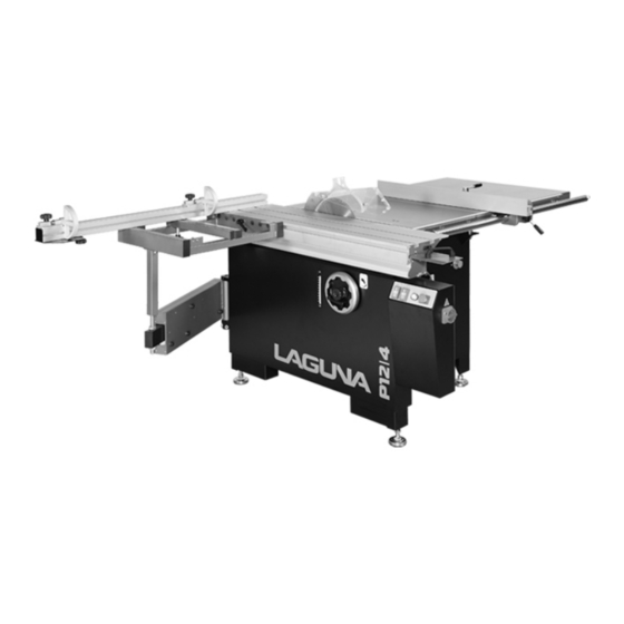
- Page 1 P12|4 Pro Panelsaw Manual LAGUNA TOOLS 2072 Alton Parkway Irvine, California 92606 Model Number: MPSP12-4-0135 Ph: 800.234.1976 www.lagunatools.com © 2018, Laguna Tools, Inc. LAGUNA® and the LAGUNA Logo® are the registered trademarks of Laguna Tools, Inc. All rights reserved.
-
Page 2: Table Of Contents
Table of Contents I. GENERAL INFORMATION 1-1. General information & safety rules …………………………………………………... p4 II. SPECIFICATIONS Features…………………………………………………………………………………….…p9 Specifications…………………………………………………………………..…………….p10 III. INSTALLATION Unpacking……………………………………………………………….…………….……...p11 Check the machine items..…………………………………………….…………….. p11 1. Installation of control panel……………………..…………………………..….……. p12 2. Installation of the crosscut table and fence …………………………..….…..……p12 3. - Page 3 PARTS LIST…………………………………………………………………………….. ASSEM01- Machine body & table …………………………………………………. ASSEM02- Control panel ……………………………………………………... ASSEM03- Power unit ……………………………………………………………… ASSEM04- Saw blade angel device ………………………………………………… ASSEM05- Saw blade rise & fall device ……………………………………………. ASSEM06- Scoring device …………………………………………………………… ASSEM07- Outrigger arm ……………………………………………………………. ASSEM08- Crosscut table ……………………………………………………………. ASSEM09- Crosscut fence ……………………………………………………………...
-
Page 4: General Information & Safety Rules
1. GENERAL INFORMATION & SAFETY RULES OAV Equipment & Tools, Inc. specializes in supplying a full series of panel saws: from 1600, 2300, 2500, 3200 and 3800mm. The design of this machine is unique, and includes an enlarged outrigger and carriage, and a direct dust collection outlet. We sincerely hope that you enjoy operating this machine. - Page 5 Anyone who operates the machine must first be properly trained. It is very important that anyone who operates the machine first reads and understands all of the safety measures outlined in this manual. They must also obey and execute the regulations stated in this manual, and learn the machine's applications and limitations, as well as the specific hazards particular to the machine.
- Page 6 11) No smoking!! Please do not smoke while operating the machine. 12) Have your machine repaired by a qualified person. Repairs should only be carried out by specially trained, qualified people, using original spare parts; failure to do this may result in injury or death. 13) Check any damaged parts.
- Page 7 21) What to do in an emergency: This machine is equipped with two emergency buttons. One is a self-latching push button on the control panel. The other emergency button is positioned on the front side of the machine, near in-feed work area. The emergency button is red with a yellow background. After the emergency stop, unlock the emergency stop button, and follow normal start up procedure and perform the suitable operation to eliminate the hazard.
- Page 8 body parts could get close to the area of the saw blade. Push blocks should be between 300mm and 400mm long, 80mm to 100mm wide and 15mm to 20mm tall. Push blocks should be utilized when cutting small work pieces and in circumstances where it is necessary to push the work piece against the fence.
-
Page 9: Main Features
D30B2 Main Features 1. Cast Iron rip Fence: Micro adjustment for smooth and precise cutting 2. Standard Guard (one piece): Fully adjustable blade maintains, protection around the saw blades. 3. Crosscut table: to support large panel size during crosscutting operation. 4. -
Page 10: Specifications
SPECIFICATIONS: ITEM P12 4 Sliding table dimension 1300x316 Cast iron table 548X896mm Extension table (rear) 952X896mm Table size 1500x896 mm ∮40 Round rail Main saw blade (Max.) 305mm Main saw bore 30mm Max. cutting height with blade at 90∘ 90mm Max. -
Page 11: Unpacking
UNPACKING SETUP SAFETY – Please keep this manual near the machine for your reference. Please follow the instructions set forth by this manual precisely. – Provide sufficient space around the work area, and keep the area around the machine clean and free of scraps, debris, oil, and grease. - Page 12 Installation ** Use forklift to move the machine or minimum 4 people to move together. (1) Control panel Install control panel with 4 Hex nuts, Lock washer, washer to mount it to the machine right hand side. 1. Main Switch P ower on and power off the panel saw.
- Page 13 (3) Crosscut fence 1. Slide the center stud(M8x1.25), T-bolt (M8x12.5px60) , T-nut (M8x1.25) into crosscut fence T-slot. (Fig. 3C) 2. Insert the crosscut fence to the crosscut table, align the center stud, T-bolt, T-nut to the position. (Fig.3A) 3. Hold the crosscut fence again the 90 degree stop bolt, tighten with the knob to lock the crosscut position. (Fig. 3B) 90 degree stop can do the micro adjustment to be 90 degree (square) with the blade.
- Page 14 (4) Remove the shipping brace on the slipping table, attached the sliding table handle. 1. Remove the red shipping brace from the sliding table (Fig.4A), install the sliding table end cover (Fig. 4C) to the sliding table use button head screw with washer (M6x16). (Fig.4B) 2.
- Page 15 (5) Fitting the extension table The sliding table was installed on the machine and calibrated to the cast iron table in manufacture. 1. Before the tables are leveled, do not tighten the bolts in follow steps. 2. Attach the large extension table with three cap screws, lock washers and flat washers (Fig. 5A) 3.
-
Page 16: Moving And Fixing The Base Unit
5. Slide the rip fence body onto the rail, then place the adjustable ring on the sliding table end of the rail and secure the ring with the set screw (Fig. 6D) 6 . Thread the lock handles (Fig. 6E) into the rip fence body and loosely install the fine adjustment knob. 7. -
Page 17: Operation And Maintenance
Operation and maintenance (9) Riving knife and saw blade 1. Riving knife M aintains kerfs opening during cutting : operations. The Purpose is crucial to preventing kickback caused by the deaf closing behind the blade. 2. Main saw blade T he maximum is 305 mm. :... - Page 18 (11) Scoring Blade Aligning Scoring Blade Set The scoring blade must be aligned with the main blade to ensure satisfactory cutting results. 1. Move the blade tilt to 0° (blade 90° to table) and raise the main blade all the way up. Fig.
- Page 19 (13) Changing Scoring Blade 1. Discount the saw from the power source. 2. Move the blade tilt to 0° (blade 90° to table), and raise the scoring blade all the way up. 3. Move the sliding table all the way forward to expose the internal blade guard that covers the blade and riving knife.
-
Page 20: Rip Cutting With The Sliding Table
(16)Rip Cutting With The Sliding Table : : : : 1. Install the crosscut fence in the center stud hole. Note P ut the crosscut fence into the center stud hole : and adjust it against to the 90° stop. (Fig. 16A) Check to make sure the fence is at 90°... -
Page 21: Crosscutting
optional (17) Crosscutting This saw can crosscut full size panels with the fence in forward mounted the forward or rear position, although it is easier to load full crosscut size panels with the crosscut fence mounted in the forward position. (Fig. 17A) Fig. - Page 22 (18) Lubrication Lubrication the areas indicated below every 6-12 months, depending on frequency of use. 1. Blade angling trunnion. 2. Sliding table ways. 3. Scoring blade worm gear 4. Blade height linkage. 5. Blade height bearing 6. Blade tilt worm gear 7.
-
Page 23: Sliding Table Parallel Adjustment
(9) Blade Tilt 1. Disconnect the saw from the power source. 2. Move the blade tilt to 90° according to the gauge, and raise the main blade. 3. Place a machinist's square between the teeth on the blade and on the table surface and inspect for gaps between the blade and the square. -
Page 24: Squaring Crosscut Fence To Blade
(21) Squaring Crosscut Fence to Blade 1. Make sure the blade is parallel with the sliding table. 2. Prepare the scrap test piece by cutting it to 32" x 32" and number all four sides of the test piece. 3. Using the crosscut fence, cut 1/2" off of each side of the test piece. -
Page 25: Tool Box
Tool Box... - Page 28 MPSP12-4-0135 ASSEM 1.1.1...
- Page 29 MPSP12-4-0135 ASSEM 1.1.1 PART NAME SIZE Q`TY ITEM PART NO NOTE PS062500 Spring Pin ψ6x25 Hex Head Bolt M10x40 SH100800 Hex Nut NH101700 Machine frame 206345 Plate for 1300 sliding table 207251-37 Plate for 2200 sliding table 207251-37A Cap Screw...
- Page 30 MPSP12-4-0135 ASSEM 1.1.1 PART NAME SIZE Q`TY ITEM PART NO NOTE 201105 Power Box Power Box 201105A Terminal PB2504 4P 994805 Pan Head Screw M5x8 SP059200 Button Head Screw M5x12 SJ059300 Strain Relief PG20 709421 Plate 206342 Plate 206345-32 Pan Head Screw(+)/W...
- Page 31 MPSP12-4-0135 ASSEM 1.3.4...
- Page 32 MPSP12-4-0135 ASSEM 1.3.4 PART NAME SIZE Q`TY ITEM PART NO NOTE SS100400 Set Screw M10x20 Hex Nut NH101700 Cap Screw M10x25 SR100500 Table 206332 Ext. Plate 207078 Washer M10xψ20 WF102030 Lock Washer WS100000 Button Head Screw M6x12 SJ069300 Table Insert...
- Page 33 MPSP12-4-0135 ASSEM 2.5...
- Page 34 MPSP12-4-0135 ASSEM 2.5 PART NAME SIZE Q`TY ITEM PART NO NOTE 994810 Button Switch HY57(1A1B) Label 207265 Pilot Lamp YK.24V φ22 (W) 996002 Emergency Stop Button 994808 Plate 206376 Hex Nut NF061000 Washer M6xψ13 WF061310 Electric.Panel 400V 3~ 200867 Plate...
- Page 35 MPSP12-4-0135 ASSEM 3.1 PART NAME SIZE Q`TY ITEM PART NO NOTE Cap Screw M6x12 SR069300 Lock Washer WS060000 Cap Screw M5x16 SR059400 Fix Plate 206337 Washer M5x10 WF051010 Lock Nut NL050800 SR059300 Cap Screw M5x12 Lock Washer WS050000 Hex Head Bolt(+)/W...
- Page 36 MPSP12-4-0135 ASSEM 3.1 PART NAME SIZE Q`TY ITEM PART NO NOTE 203249 Magnetic Iron(assembly) Magnetic Iron 203249-1 Screw 203249-3 Sunkhead Socket Screw M6x20 SM060400 Dust Port 206118 Cover 206324 Hinge 207940 Washer M5x10 WF051010 Lock Washer WS050000 Cap Screw M5x8...
- Page 37 MPSP12-4-0135 ASSEM 3.3 PART NAME SIZE Q`TY ITEM PART NO NOTE Belt 3VX-265 208044 50Hz Belt 3VX-250 206399 60Hz Setscrew M8×10 SS080200 Belt Pulley 50Hz 208043 208042 Belt Pulley 60Hz Shaft 201333 Main Motor Plate 206396 WF132225 Washer M13×ψ22 Lock Washer...
- Page 38 MPSP12-4-0135 ASSEM 3.4.1 PART NAME SIZE Q`TY ITEM PART NO NOTE Gip Plate 206304 Button Head Screw M10×25 SJ100500 Spring Washer WS100000 KD050520 5x5x20 M16x2.0 201822 Arbor Flange 206350 optional ψ25.4 Arbor Flange 206380 ψ30 Lock Washer WS080000 Washer M8×ψ30...
- Page 39 MPSP12-4-0135 ASSEM 3.4.1 PART NAME SIZE Q`TY ITEM PART NO NOTE 103 SS050200 Setscrew M5×10 Pulley 104 208041 Rotate Plate 105 206302 Wave Washer 106 WW476004 ψ47×ψ60 Main Arbor 206357 ψ30 Main Arbor 206310 optional ψ25.4 Washer M8×ψ30 108 WF083030...
- Page 40 MPSP12-4-0135 ASSEM 4.1 ITEM PART NO PART NAME SIZE Q`TY NOTE Lock Knob 100203 Washer 204263 ψ10×ψ20 M10×ψ27 (for Washer plastic hand WF102730 Standard wheel) M10×ψ40 (for Washer cast iron hand WF104030 Optional wheel) hand wheel 8"(plastic) 206434A Standard hand wheel 8"(cast iron)
- Page 41 MPSP12-4-0135 ASSEM 4.1 PART NAME SIZE Q`TY ITEM PART NO NOTE AB207462 Hand Wheel Shaft Assembly Hand Wheel Shaft 101 207462 Bearing 6902ZZ 102 BB690202 Locate Ring 103 207252 Ext. Retaining Ring 104 RR280010 Thrust Bearing NTB1528+AS 105 994204 Free Joint 106 207461 ψ14...
- Page 42 MPSP12-4-0135 ASSEM 5.1 PART NAME SIZE Q`TY ITEM PART NO NOTE Lock Knob 100203 Washer 204263 ψ10×ψ20 Washer M10×ψ30 WF103030 204289B Hand Wheel Plastic standard Hand Wheel Cast iron 204176A optional Bushing 200855 Sleeve 206385 Screw 206327 Setscrew M6×6 SS069100...
- Page 43 MPSP12-4-0135 ASSEM 5.1 PART NAME SIZE Q`TY ITEM PART NO NOTE SJ060200 Cap Screw M6×10 Setscrew M10×35 SS100700 Hex Nut NH101700 Setscrew M8x10 SS080200 Bearing Self Lubricating 017177 Handle M10 7" 206460 WF101608 Washer M10×ψ16×t0.8...
- Page 44 MPSP12-4-0135 ASSEM 6.2 PART NAME SIZE Q`TY ITEM PART NO NOTE Pulley ASM AB206315-1 Hex Head Bolt M12×20 101 SH120440 Flange 102 206320 103 206321 Shaft Ball Bearing 6202LLB (black) 104 BB620204 Int. Retaining Ring 105 RS150000 Wave Washer WW263403 ψ26xψ34 t=0.3 ( 6202 )
- Page 45 MPSP12-4-0135 ASSEM 6.2 PART NAME SIZE Q`TY ITEM PART NO NOTE 121 206386 Set Screw M6x25 Hex Nut 122 NH061000 Hex Nut 123 203239 Spring Pin 124 PS031200 ψ3x12 Screw 125 206317 Ball Bearing 6003LLB (black) 126 BB600304 Cap Screw...
- Page 46 MPSP12-4-0135 ASSEM 6.4 PART NAME SIZE Q`TY ITEM PART NO NOTE Cap Screw M12x100 SR122000 Lock Washer WS120000 Pully 206314 50Hz 206336 Pully 60Hz Belt 140J7 LJ014070 60Hz Belt 150J7 LJ015070 50Hz Shaft 206313 Button Head Screw M8x20 SJ080400 Lock Washer...
- Page 47 MPSP12-4-0135 ASSEM 7...
- Page 48 MPSP12-4-0135 ASSEM 7 PART NAME SIZE ITEM PART NO Q`TY NOTE AB204241 SLIDING TUBE ASM. Cover 204239 Pan Head Screw M4x10L SP040200 Cover 204240 ROLL ASM. AB203348 AB203356 Setscrew 204135 Bearing 6202ZZ BB620202 Swing Arm 204038 Brush 135051 WF061310 Washer M6×13...
- Page 49 MPSP12-4-0135 ASSEM 8...
- Page 50 MPSP12-4-0135 ASSEM 8 PART NAME SIZE ITEM PART NO Q`TY NOTE AB201951 EXTENSION FRAME T-Nut M12xP1.75 201855 Washer M12xψ30xt3 WF123030 Adjust Handle M12xP1.75x55L 200815 Washer M8xψ30xt3mm WF083030 optional Knob Screw M8x50L 200954 optional T-Nut M8xP1.25 201103 optional Washer WF061620 Lock Washer...
- Page 51 MPSP12-4-0135 ASSEM 9...
- Page 52 MPSP12-4-0135 ASSEM 9 PART NAME SIZE ITEM PART NO Q`TY NOTE AB204268 Ext. Fence Asm. Flip Stop AB200823-1 Knob Screw M8x1.25px25L 201886 T-Nut M8x1.25p 201103 Block 201465 Lock Washer WS080000 Cap Screw M8X35 SR080700 T-Bolt M8×1.25p×60L 200953 Washer M8X30 WF083030 Knob Screw M8×55...
- Page 53 MPSP12-4-0135 ASSEM 10.1 PART NAME SIZE Q`TY ITEM PART NO NOTE Rip Fence Housing Assembly AB206422 Counter Sunk Screw M6x16 101 SI069400 Fixed Plate 102 206433 Shafts 103 203193 Lock Nut 104 NL081000 105 200875 Plate Hex Head Bolt M6x16...
- Page 54 MPSP12-4-0135 ASSEM 10.1 PART NAME SIZE Q`TY ITEM PART NO NOTE 115 WS080000 Lock Washer Ball Bearing 6202ZZ 116 BB620202 Hex Nut 117 NA081300 Ring 118 203356 Ring 119 206435 Washer M8xψ30 120 WF083030 Hex Head Bolt M8*35 121 SH080700...
- Page 55 MPSP12-4-0135 ASSEM 11.2...
- Page 56 MPSP12-4-0135 ASSEM 11.2 PART NAME SIZE Q`TY ITEM PART NO NOTE 2316130B Sliding Table Set 1300×316 Cap Screw M12×35 201666 Washer M12xψ24 WF122430 Lock Washer WS120000 Hex Nut M12×P1.75 NH121900 Lock Washer WS060000 Washer M6xψ13 WF061310 Hex Nut M16× P1.5...
- Page 57 MPSP12-4-0135 ASSEM 12.3 PART NAME SIZE Q`TY ITEM PART NO NOTE AB205075 Hood Assembly Hood 101 205075 Screw M3×16 102 ST029404 Screw M3×12 103 ST029304 Hood 104 205076 Screw M5×10 105 203110 Shaft 106 205124 Lock Nut 107 NL101700 Cap Screw M10×25...
- Page 58 Laguna Tools is not responsible for errors or omissions. Specifications subject to change. Machines may be shown with optional accessories. © 2018, Laguna Tools, Inc. LAGUNA® and the LAGUNA Logo® are the registered trademarks of Laguna Tools, Inc. All rights reserved.
Need help?
Do you have a question about the MPSP12-4-0135 and is the answer not in the manual?
Questions and answers