
Related Manuals for Laguna Tools MBAND18BX2203


Summary of Contents for Laguna Tools MBAND18BX2203
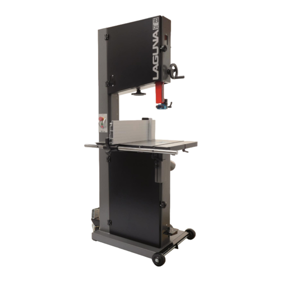
- Page 1 BANDSAW OWNER'S MANUAL Part No. MBAND18BX2203 LT18BX Bandsaw 220V 3HP 16" Resaw © 2022, Laguna Tools, Inc. LAGUNA® and the LAGUNA Logo® Revision 3, 2/10/2022 are the registered trademarks of Laguna Tools, Inc. All rights reserved.
- Page 2 Laguna 18bx Bandsaw Model mband18bx2203 Motor 3 HP, 230V Max: 145-1/2” Blade Length Min: 143-3/4” Serial No. Table of contents. Page number Safety Rules Warranty Specification sheet Noise emission Receiving your machine Introduction to Bandsaws What you will receive with your Bandsaw...
- Page 3 Safety Rules Laguna Tools MBAND18BX2203 Bandsaw User Manual...
- Page 5 Table A Ampere Rating Volts Total length of cord in feet More Than Not More Than Minimum gage for cord Not Recommended GROUNDING INSTRUCTIONS 1. All grounded, cord-connected tools: In the event of a malfunction or breakdown, grounding provides a path of least resistance for electric current to reduce the risk of electric shock.
- Page 6 reconnection; and after reconnection, the tool should comply with all local codes and ordinances. Locking the bandsaw. It is strongly recommended that the bandsaw is never be left unattended in the unlocked condition.
- Page 7 To lock the machine it is recommended that a cover (not supplied) is made to lock the control panel. We have supplied two concepts for locking the panel (see below). The cover can be made from wood or plastic. First, push down the emergency stop. Then lock the cover together by putting padlocks [not included] on the two handles on the control panel.
- Page 8 Machines sold through dealers must be registered with Laguna Tools within 30 days of purchase to be covered by this warranty. Laguna Tools guarantees all new machines and accessories sold to be free of manufacturers’...
- Page 9 Only new machines sold to the original owner are covered by this warranty. For warranty repair information, call 1-800-332-4094. Specification. MBAND18BX2203 Motor voltage/hp 230V / 3 HP Breaker 15 amp Throat 18 7/32" (463mm) Table cast iron 20" x 26" (508mm x 660mm)
- Page 10 Industrial work-light Optional Fence Face Dimensions 7 1/4" x 2 2 3/4"...
- Page 11 Noise Emission. Notes concerning noise emission Potential hearing loss depends on both noise level and exposure time, so the need for supplementary precautions cannot be precisely determined. In addition to noise level and exposure time, other factors affecting potential hearing loss include characteristics of the working environment.
- Page 12 Introduction to Bandsaws. This bandsaw is designed to give you years of safe service. Read this owner’s manual in its entirety before assembly or use. The bandsaw is generally defined as a saw blade in the form of an endless steel band that rotates around two or more wheels.
- Page 13 bandsaw blade is thin, it can cut thick stock with a minimum of horsepower. For this reason, the bandsaw is often used when valuable pieces of wood are made into a thin piece of veneer. What you will receive with your Bandsaw. Fence...
- Page 14 Fence parts Fence guide bar Fence stop...
- Page 15 Table ratchet handles & washers Rubber feet and fixings Table Fence guide bar attachment parts T bar Parts of the Bandsaw. Note: The mobility kit and light are optional. 16 6 12 13...
- Page 16 17 14 The bandsaw does not have many parts. The major parts are discussed in this manual. If you are not familiar with the bandsaw, take the time to read this section and become familiar with the machine.
- Page 17 1. Tension indicator / window. 4. Frame. Tension indicators are designed to indicate the compression of Emergency stop button a spring. As a rule, the greater the spring compression, the greater the tension on the blade. The tension scale does not register until the blade is relatively taut and is located on the inside of the body of the bandsaw.
- Page 18 or fitting a blade. Blade guide adjustment hand wheel. The upper blade guides are attached to the blade guide shaft. The shaft is vertically adjustable with a hand wheel. The guides should be adjusted so the guides are just above the wood being cut.
- Page 19 13. Blade-tracking knob. The blade-tracking knob is located at the back of the bandsaw and is used to adjust the blade tracking. The knob must be locked once the adjustment is completed. Optional mobility kit. Swivel wheel assembly The optional mobility kit is fitted to the base of the bandsaw and consists of two fixed wheels at the front of the bandsaw and a swivel wheel at the back of the band saw.
- Page 20 There is a plate at the back of the machine listing all the manufacturing data, including the serial Laguna 18bx Bandsaw number, model, and blade length. Model mband18bx2203 23. Magnetic Blade Tension Gauge Motor 3 HP, 230V Indicates blade type (Width) when installing and Max: 145-1/2”...
- Page 21 Before you remove your bandsaw from the packaging, select the area where you will use your machine. There are no hard-and-fast rules for its location, but below are a few guidelines. 1. There should be an area at the front and back of the machine suitable for the length of wood that you will be cutting.
- Page 22 Assembling the rubber feet. Method 1. Fit the rubber feet to the bandsaw prior to removing it from the packaging. Method 2. 1. Support the bandsaw on wooden blocks. 2. Assemble the rubber feet with the fixings provide both at front and back of the bandsaw.
- Page 23 Bandsaw supported on wooden block 1. Support the bandsaw on wooden blocks. 2. Fit the swivel assembly to the back of the bandsaw with the provided bolts. 3. Fit the front wheels to the front of the bandsaw with the bolts provided and remove the two rubber feet that are close to the front wheels..
- Page 24 Tilt blanking disc Table tilt hole Tilt Stop Bolt Tilt blanking disc The table has a reference stop bolt that is used to quickly align the table after tilting. The stop bolt hits the tilt-blanking disc when it is positioned over the table tilt hole. When the tilt blanking disc is moved away from the hole, it allows the tilt stop bolt to pass through the table tilt hole, and the table can be moved to the maximum amount of tilt (-6 degrees).
- Page 25 Table mounted to the bandsaw Trunnion clamp stud Ratchet handle With the table fitted to the trunnions, assemble the two ratchet handles and flat washers. How to adjust the table for square to the blade. This will be detailed later in the manual. Fitting the table rule.
- Page 26 Note. The distance between the fixing holes and the end of the bar is not symmetrical, and the end that has the longest distance must be at the back of the bandsaw (closest to the column). 2. Slide the fence support onto the fence bar and fit the fence support clamp screw. 3.
- Page 27 Fence clamped in low position Fence in low position Allen key Fence in high position Support Allen screw The fence support and the fence are held off the table with a nylon-support Allen screw. This screw ensures that the fence and the fence support do not damage the table. The screw is adjustable to compensate for wear.
- Page 28 Fitting the Fence Stop The fence stopper can be used to control the length of cut for non through cuts . To set the stop in place, the scale should be attached into the T-slot on top of the fence when it is on the vertical position.
- Page 29 Fitting the optional light. Fixing screws and cable clips Light fitted in position Suggested cable route Light plugged into socket...
- Page 30 The light is fitted to the top of the bandsaw as shown. The light is supplied with a three-pin plug 220V. The cable must be held in position with the clips provided and positioned so that the cable is safe and will not in any way come close to the blade or cabinet door. Above is the suggested cable route.
- Page 31 10. With the machine running (no blade fitted), operate the red stop switch by pressing toward the machine. The motor should have the power turned off and slow down. 11. If the switches fail to operate correctly, do not use the machine until the fault has been corrected.
- Page 32 Fitting a blade to the bandsaw. A lot of people do not like to change the blades and go to great lengths to avoid doing it. To use the bandsaw to its greatest advantage, you will have to use the appropriate blade and track it quickly.
- Page 33 6. Inspect the teeth and the general condition of the blade. If the teeth are pointing in the wrong direction when you hold the blade up to the machine, you will have to turn it inside out. To do this, hold the blade with both hands and rotate. 7.
- Page 34 Tracking knob Blade guard door Blade in column slot Once the blade is tracking in the correct position, fully tension the blade and re-track. Lock the tracking adjustment handle. Note. Tensioning the blade is covered later in the manual. 2. Refit the plastic blanking block. Note: The blade must be fully tensioned for final tracking.
- Page 35 their blades, or range of blades, and will not necessarily give you accurate readings in lbs./square inch on another manufacturer’s blades because their blades stretch at a different rate. There is nothing quite as quick or as accurate as experience. Your machine is fitted with a blade tension indicator, which measures the deflection of the tension spring on the upper flywheel.
- Page 36 detract from the performance of the machine and in extreme cases cause vibration. Removing the tension will greatly enhance the life of the machine, bearings, and tires. Label the machine “detensioned.” On the label, mark the number of turns that you detensioned;...
- Page 37 As with the roller guide systems, the Laguna guide system will damage your blade if it is not adjusted correctly. The guide blocks must not meet the teeth of the blade. It is advisable to run the blade by hand with the guide blocks completely clear of the blade, and only when you are completely sure that the blade is running consistently in the correct position, you may then adjust the surround guide blocks as detailed in this manual.
- Page 38 touches the back of the blade and lock in Side guide clamp screw position. Loosen the guide clamp screw that allows the side guides to move forward and back. Adjust so that the ceramic blocks are just behind the gullet of the teeth and are parallel to the blade.
- Page 39 forward and back. Rotate the blade by hand and ensure that it is tracking consistently in the correct position. Loosen the side guides and move out from the blade. Loosen the two clamp screws that allow the guide assembly to move forward and back.
- Page 40 Although the bandsaw is usually associated with cutting curves, a variety of straight cuts are easily made with the saw. In fact, it is often used to rip wood because it is much safer than a radial arm saw and has a smaller saw cut, so it wastes less wood. This becomes very important when using expensive wood where waste must be kept to a minimum.
- Page 41 1. Set the fence parallel with the blade by loosening the clamp screws that hold it to the cast bracket. It is not important that it is exact because you will be readjusting later in the procedure. 2. Using a piece of scrap wood, make a cut while holding the wood against the fence. Stop the cut in the middle of the wood.
- Page 42 Table rule Adjustment slot Fence position. Fence in low position Fence in high position The aluminum fence can be used in two height positions (high and low). The low position is handy for cutting thin wood and is used where the fence in the high position would make it awkward to complete cuts.
- Page 43 Resawing is the process of cutting a board in half along its height. The bandsaw is perhaps the most creative tool in the shop because of its ability to cut thick or thin, straight, or curved. The ability to cut thick stock such as re-sawing, making veneers, book matching or cutting flitches from small logs has great appeal to the woodworker.
- Page 44 Thickness. The thicker the blade, the stiffer the blade and the straighter the cut. The thicker the band, the greater the tendency for the blade to break. Pitch. The size of the teeth. This is usually quoted in teeth per inch (TPI). The larger the tooth, the faster the cut because the tooth has a large gullet and has a greater capacity to transport large amounts of sawdust through the job.
- Page 45 Width. The dimension from the back of the blade to the front of the teeth. The wider the blade, the stiffer the blade and the straighter the cut. This is usually called beam strength. But wide blades cannot cut small radiuses. The narrower the blade, the more flexible the blade and the greater the tendency the blade must wander.
- Page 46 that listed below, which is a good general selection and will allow you to tackle most jobs. As you gain experience, you will settle on the blades that suit you. 1/4" 6 TPI. This is a small, aggressive blade that is suitable for tight curves and fast cutting where a good surface finish of the cut is not important.
- Page 47 3. Incorrect tension, particularly if the blade is over tensioned; the tension spring no longer fulfils its function. 4. After use it is recommended that you slacken the tension, especially overnight. (Be sure to place a clearly visible note on the machine that you have done this. 5.
- Page 48 3/16" blade will cut a circle with a 5/16" radius or a 5/8" diameter. To test if a 3/16" blade would work for a particular curve, place a dime (roughly 5/8") over the pattern. The 3/16" blade can cut a curve bigger than the dime, but not smaller. You can use everyday items such as coins or a pencil to determine which blade to use.
- Page 49 Step 1 Step 2 Step 3 Done Note: To show the hand/thumb position of the man in the photographs, he is not wearing gloves, but gloves MUST BE WORN as the blade could cause injury. Method Two. There is another variation of this that works well with small blades but simply is not possible for larger bandsaw blades, unless you are very big and strong.
- Page 50 Step 1 Step 2 Step 3 Step 4 Done Method Three. The steering wheel method. Start with the blade in front of you, as if you are holding a steering wheel with your hands at the 9 o'clock and 3 o'clock positions. Simultaneously twist your left hand up and your right hand down.
- Page 51 Step 1 Step 2 Done Step 3 Step 4 Maintenance.
- Page 52 All tools and machines require regular maintenance, and the bandsaw is no exception. This section details the general maintenance and care of your bandsaw. In general, we recommend that you only use a Teflon-based lubricant on the bandsaw. While regular oil attracts dust and dirt, Teflon tends to dry and has fewer tendencies to accumulate dirt and sawdust on your machine.
- Page 53 Drive belt adjusting bolt Motor drive pulley Drive belt Flywheel shaft nut To replace the belts you will have to remove the lower flywheel. 1. Loosen the motor clamp bolts and move the motor so that the tension is completely removed from the drive belt.
- Page 54 Rust. The bandsaw is made from steel and cast iron. All non-painted surfaces will rust if not protected. It is recommended that the table be protected by coating with wax if the machine is not in constant use. All moving non-painted surfaces (guides, rack, and pinion, etc.) should be lubricated/protected with a Teflon-based lubricant.
- Page 55 Adjusting the table square to the bandsaw blade. Note. The machine is set in the factory and no adjustment should be required but during transportation movement may occur. To access the adjustment screws, you will have to tilt the table up to 45 degrees and lock in position. The adjustment is made with the jacking screws 1 &...
- Page 56 Tilt stop bolt bolt to pass through the table tilt hole, and the table can be moved to the maximum amount of tilt (-7 degrees). To adjust the table square to the blade. 1. Check that the stop bolt is in contact with the tilt-blanking disc. 2.
- Page 57 3. Re check the fence for square and re-adjust if required. Troubleshooting. Bandsaw will not start. 1. Check that the start switch is fully pulled out. 2. Check that the yellow safety plug is fully engaged. 3. Check that the electrical power cord is plugged into the power outlet. 4.
- Page 58 3. Bent rack. Replace the rack. Blade slows down during a cut. 1. Loose drive belt. Re-tension the belt. 2. Dull blade. Replace the blade or have it re-sharpened. 3. Feeding the wood too fast. Slow down the feed rate. 4.
- Page 60 LT18BX (MBAND18BX2203)220V wiring diagram.
- Page 61 Part No Item Description Specification Upper Wheel Assembly PBAND18BX2203-1 Hex Nut 5/8-18UNF-LH PBAND18BX2203-2 Ball Bearing 6204LLU PBAND18BX2203-4 PU Tire PBAND18BX2203-5 Upper Wheel PBAND18BX2203-6 Upper Wheel Shaft PBAND18BX2203-7 Upper Wheel Shaft Bracket 3/8”-16x5/8" PBAND1412-175-9 Socket Head Cap Screw PBAND18BX2203-10 Sliding Bracket PBAND18BX2203-11 Hex Cap Screw M8x80...
- Page 62 PBAND1412-175-170 Switch Plate PBAND18BX2203-13 Bushing PBAND18BX2203-14 Nylon Inserted Lock Nut PBAND18BX2203-15 Pointer PBAND18BX2203-16 Special Bolt PBAND18BX2203-17 Spring PBAND18BX2203-18 Bracket PBAND1412-175-19 Ø4x20 PBAND18BX2203-20 Adjusting Screw PBAND18BX2203-21 Blade Tension Arm Assembly PBAND18BX2203-22 Support Block PBAND1412-175-23 Plate PBAND1412-175-24 Handle PBAND1412-175-25 Door Hinge Set PBAND1412-175-25-1 Door Hinge, Left PBAND1412-175-25-2...
- Page 63 MBAND14BX110-175-36 ON/ OFF Switch PBAND1412-175-37 Screw M5x0.8x16 MBAND14BX220-250-38 Outlet PBAND1412-175-39 Washer, Lock-Int. Tooth MBAND14BX220-250-40 Contactor PBAND1412-175-41 Hex Cap Screw 1/4"-20x5/8" PBAND1412-175-42 Lock Washer 1/4" PBAND1412-175-43 Set Screw 1/4"-20x3/8" PBAND18BX2203-44 Handwheel PBAND1412-175-45 Screw 1/4"-20x3/4" PBAND1412-175-46 Lock Knob PBAND18BX2203-47 Saw Body PBAND1412-175-48 Lock Knob PBAND1412-175-49 Adjusting Knob...
- Page 64 MBAND14BX110-175-67 Washer, Lock-Int. Tooth MBAND14BX110-175-68 Screw M4x0.7x8 Part No Item Description Specification Lower Wheel and Motor Assembly PBAND18BX2203-1 Hex Nut 5/8-18UNF-LH PBAND18BX2203-2 Ball Bearing 6204LLU PBAND18BX2203-2-3 Plate PBAND18BX2203-4 PU Tire...
- Page 65 PBAND18BX2203-2-5 Lower Wheel PBAND18BX2203-2-6 Poly-V Belt PBAND18BX2203-2-7 Motor Pulley PBAND1412-175-2-8 Set Screw 5/16"-18x3/8" PBAND1412-175-2-9 6x6x40 MBAND14BX110-175-2-10 Flat Washer 1/4" PBAND1412-175-2-11 Flat Washer 5/16" PBAND18BX2203-2-12 Spindle Pulley MBAND14BX110-175-2-13 Plate MBAND14BX110-175-2-14 Phillips Flat Head Screw 5/16"-18x1-1/2" PBAND18BX2203-2-15 Lower Spindle PBAND1412-175-2-16 Hex Cap Screw M5x0.8x30 PBAND1412-175-2-17 Flat Washer...
- Page 66 1/4”-20 PBAND1412-175-2-30 Hex Nut PBAND1412-175-2-31 Door Stud 1/4” PBAND1412-175-2-32 Flat Washer 1/4”-20 PBAND1412-175-2-33 Nylon Inserted Lock Nut PBAND1412-175-2-34 Lock Knob PBAND1412-175-2-35 Screw 1/4"-20x3/4" PBAND1412-175-2-36 Plate PBAND1412-175-2-37 Screw #10-24×3/8" PBAND1412-175-2-38 Strain Relief 6N-4 MBAND14BX110-175-2-39 Motor Cord MBAND14BX220-250-2-40 Power Cord PBAND1412-175-2-276 Bushing PBAND1412-175-2-42 Flat Washer 3/8"...
- Page 67 MBAND14BX110-175-2-54 Hex Cap Screw M6x1.0x35 MBAND14BX110-175-2-55 Hex Nut 3/8"-16 PBAND18BX2203-2-56 Foot Brake MBAND14BX110-175-2-57 Hex Cap Screw 5/16-18UNCx1/2 MBAND14BX110-175-2-58 Hex Cap Screw 3/8-16UNCx1-1/4" MBAND14BX110-175-2-59 Spring MBAND14BX110-175-2-60 Limited Switch MBAND14BX110-175-2-61 Screw M3×20mm MBAND14BX110-175-2-62 Screw 1/4"-20x3/8" MBAND14BX110-175-2-63 Brake Assembly MBAND14BX110-175-2- Brake Pad (not shown), 2 pieces MBAND14BX110-175-2-64 Disc MBAND14BX110-175-2-65 Inner Cable MBAND14BX110-175-2-66 Housing...
- Page 69 Part No Item Description Specification Table and Fence Assembly PBAND18BX2203-3-1 Aluminum Fence PBAND1412-175-3-2 Plastic Adjusting Screw PBAND1412-175-3-3 Fence Body PBAND1412-175-3-4 Lock Knob PBAND1412-175-3-5 Socket Head Cap Screw 5/16"-18x3/4" PBAND1412-175-3-6 Lock Washer 5/16" PBAND1412-175-3-7 Fence Head PBAND18BX2203-3-8 Lock Knob PBAND1412-175-3-9 Lock Bar PBAND1412-175-3-10 Set Screw M4x0.7x4...
- Page 70 PBAND1412-175-3-27 Pointer PBAND1412-175-3-28 Screw M5x0.8x8 PBAND1412-175-3-29 Bracket PBAND1412-175-3-30 Flat Washer 3/8" PBAND1412-175-3-31 Lock Handle PBAND1412-175-3-32 Hex Cap Screw 5/16"-18x1-1/4" PBAND1412-175-3-33 Set Screw 5/16"-18x5/8" PBAND1412-175-3-34 Hex Cap Screw 5/16"-18x1-3/4" PBAND1412-175-3-35 Hex Cap Screw 3/8"-16×2" PBAND1412-175-3-36 Hex Nut 3/8"-16 PBAND1412-175-3-37 Phillips Flat Head Screw M4x0.7x8 PBAND1412-175-3-38 Hex Nut...
- Page 72 Part No Item Description Specification Upper and Lower Blade Guides Assembly PBAND1412-175-4-1 Lock Knob PBAND1412-175-4-2 Set Screw 5/16"-18x3/8" PBAND1412-175-4-3 Set Screw 1/4"-20x3/8" PBAND1412-175-4-4 Hand wheel PBAND1412-175-4-5 Handle PBAND18BX2203-4-6 Pointer PBAND1412-175-4-7 Screw 1/4"-20x3/8" PBAND18BX2203-4-8 Upper Blade Guard PBAND18BX2203-4-9 Height Scale PBAND18BX2203-4-10 Magnet PBAND1412-175-4-11 Guide Bar Bracket...
- Page 73 PBAND1412-175-4-27 Adjusting Block PBAND1412-175-4-28 Fixed Block PBAND1412-175-4-29 Lock Knob PBAND1412-175-4-30 Ceramic Guide PBAND1412-175-4-31 Support Shaft PBAND1412-175-4-32 Guide Bracket PBAND1412-175-4-33 Lock Handle PBAND1412-175-4-34 Support Shaft PBAND1412-175-4-35 Lock Knob PBAND1412-175-4-36 Socket Head Button Screw 1/4"-20x1/2" PBAND1412-175-4-37 Base PBAND1412-175-4-38 Special Bolt PBAND1412-175-4-39 Flat Washer 5/16"...
- Page 75 Supplier Part Number Laguna Part Number Item Description Specification 230V Industrial Work Light: Optional PBAND14BX220-250-7-1 14BX220-250-701 Work Light 230V PBAND1412-175-7-2 1412-702 Screw M4x0.7x20 PBAND1412-175-7-3 1412-703 Flat Washer PBAND1412-175-7-4 1412-704 Hex Nut M4x0.7 PBAND1412-175-7-5 1412-705 Cable Clamp...
Need help?
Do you have a question about the MBAND18BX2203 and is the answer not in the manual?
Questions and answers