
Related Manuals for Laguna Tools HW110LS-30


Summary of Contents for Laguna Tools HW110LS-30
- Page 1 latinum Series Dovetail Action Tablesaw Owner’s Manual Platinum Series Tablesaw MTS0300-0180 lagunatools.com | lagunacleanair.com | supermaxtools.com...
-
Page 2: Warranty Information
1. Foreword 2. Warranty Information This manual contains basic information for qualified Limited Warranty operating staff and describes the surroundings and One year using ways of the machine for those it is intended. Proof of Purchase It contains also all necessary information for a Please keep your dated proof of purchase for correct and safe operating. -
Page 3: Machine Description
3. Machine Description 3.1 Technical parameters Item HW110LS-30 HW110LS-50 weight 550Ibs 590Ibs Product length/width/height 62"×41"×40" 82"×41"×40" Dimensions foot print(length/width) 20"×20" Electrical: switch magnetic with thermal overload protection type TEFC capacitor start induction 3HP-230V-1PH 12.8A horsepower/voltage/phase/amps 4HP-230V-1PH Motor 5.5HP-230V(400V)-3PH 13.9A/8.0A 3450 RPM/60HZ... -
Page 4: Feature Identification
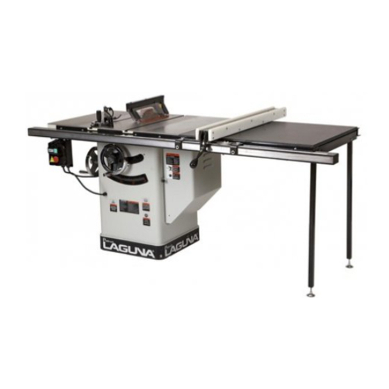
3.2 Feature Identification 3.3 Intended Use ( Fig.1) Table saw and the workpiece guide equipment supplied with it are intended to be used exclusively for the following purposes: ● Laminated and unlaminated board materials (e.g. chipboard, coreboard, MDF board, ...) ●... - Page 5 ● The intended use of the machine involves damage that is caused by using non-original spare connection to a suitably dimensioned extraction parts. system . ● Intended use also involves compliance with our The machine is prohibited to be used in a specified operating, maintenance...
- Page 6 Harmonics 3.5.3 Testing results The sum of 2nd-5th distorted harmonic must not NO LOAD LOAD exceed 10% of RMS of voltage. An additional 2% 101.3 104.1 of RMS of line voltage is allowed to for the sum of Position A 84.7 88.5 6th-30th harmonic.
-
Page 7: Safety Regulations
starter keys; 4. Safety Regulations 9. USE PROPER SPEED. 4.1 General Safety Instructions A machine will do a better and safer job when 1. KNOW YOUR MACHINE. operated at the proper speed; Read and understand the owners manual and 10. USE RIGHT MACHINE. labels affixed to the machine. - Page 8 Serious injury could occur if the machine tips 3. ALWAYS USE A PUSHSTICK OR PUSH over .Do not store materials such that it is BLOCKS. necessary to stand on the machine to reach them; Push blocks or push sticks shall be used when cutting small workpieces and in circumstances 18.
-
Page 9: Residual Risks
12. AVOID KICKBACKS. 4.3 Residual risks Avoid kickbacks (work thrown back towards you) Take precautions to reduce the hazard of by keeping the blade sharp, by keeping the rip inhalation of harmful dusts (e.g. wearing a dust fence parallel to the saw blade, by keeping the mask);... - Page 10 5. Installation of the machine 5.1 Transportation of machines If the workpieces is less then 120mm,you must 5.1.1 Transportation and store use the push stick to prevent your hands from The measures of anti-rust and shockproof should getting too close to the saw blade. Push block must be used to cut narrow be taken during packing.
-
Page 11: Installation
5.1.2 Transportation before unpacking 5.4 installation As standard, the machine is packed in a robust Before beginning assembly, take note of the wooden box. Fig.4 shows the tool can be used to following precautions and suggestions transport the packing box. ----- The machine is bolted to the pallet. - Page 12 assembled and you read and understand the 5.4.3 handwheel handle install: entire User Manual. Install the handle into the Blade Tilt & Height hand wheel as Fig.7. 5.4.1Remove the shipping brace: pull the switch out of the saw cabinet and remove the shipping brace as Fig.5 ;...
- Page 13 Fig.10-1 Fence assembled Fig.8: Extension wings install 5.4.5 install the rail & fence A. install the rear rail , front rail, tube,(extension table ) as breakdown, Before tightening the fasteners,check to make sure the top edge of rear rail is flush with the lowest edge of both T-bolts,so the miter gauge will slide smoothly when installed Fig.10-2: fence installed on rails later.
-
Page 14: Install The Switch
place the front rail tape scale on the fence tube, make sure it is parallel with the tube, and the“0” end is directly under the red line on the pointer window as shown; lightly mark the “0” location on the tube with a pencil, then remove the fence; peel the tape and carefully align the “0”... -
Page 15: Install The Blade
B. slide the blade guard spreader all the way down 5.4.7 Install the blade into the block, then rotate the knurled knob so it A. Remove blade guard assembly & table insert. disengages the bracket and the locking pin B. raise the arbor all the way up and set the blade engages the hole in the center of the spreader. - Page 16 with an ultimate tensile strength of 580 N mm-2 or 5.4.9 Connecting extraction of a comparable material, have flat sides (within 0,1 system mm per 100 mm) and shall have a thickness less than the width of cut (kerf) and at least 0,2mm greater than the saw blade plate.
-
Page 17: Electrical Installation
conveniently. 5.4.10 Electrical installation 2. The machine should be installed in a workshop with good illumination ventilation. 1. Wiring should only be done by professional 3. Over-voltage protection device should be electricians. Always make sure the machine is provided by end user on spot. properly earthed. - Page 18 Wiring: Change Connections From Finish electrical connection according to the 220V/3PH to 380V/3PH. electrical drawings. This model can be rewired from 220V/3PH to The wirings on the spot should refer to the 380V/3PH operation, this procedure takes requirements of Clause 13 (Wring practices) of EN moderate electrical skill and the rewiring job must 60204-1:2006.
- Page 19 parallel. If they are not parallel, unlock the rip fence 6. Adjustment and turn it upside down. Adjust the set screws (H) as Fig.23 in or out, verify your adjustment, repeat if necessary. Before operation, the machine should be 2.The lock lever pressure can be adjusted by carefully adjusted for best performance.
-
Page 20: Positive Stops
6.3 Aligning Table T-slot Parallel With 6.4 Adjusting 45 and 90 Degree Blade Positive Stops 1,The table T-slot must be aligned parallel with the The tilt mechanism has adjustable stops for vertical blade. Using a combination square (A) as Fig.24, and 45 degrees. -
Page 21: Electrical Operation
then adjust the 4 set screws in or out until the 7. Operations alignement is perfectly parallel. 7.1 Electrical Operation (Fig.29) 4. Reinstall the table insert. ON Button: Starts the motor (see Fig. 29 Safety Pin & Chain: When installed (see Fig.29 disables the ON Button to prevent accidental startup. - Page 22 safety. As with all power tools there is a certain to move the work slightly away from the saw blade. amount of hazard involved with the operation and Never pick up any short length of free work from use of the tool. Using the tool with the respect and the table while the saw is running.
-
Page 23: Maintenance
saw blade as shown in Fig. The work can then be 8. Maintenance fed through the saw blade with one or two hands. This table saw requires very little maintenance When this is done the work will either stay on the other than minor lubrication and cleaning. - Page 24 CHANGING BELTS WARNING: MAKE SURE THE POWER CORD IS DISCONNECTED FROM THE POWER SOURCE! 1. Lower the blade completely, then open the motor access cover. 2. Loosen the hex nuts A that secure the motor (see Fig.32 ) and raise the motor fully to remove tension on the V-belts.
- Page 25 9. Trouble Shouting Guide PROBLEM SOLUTION SAW WILL NOT START 1. Saw not plugged in. 1. Plug in saw. 2. Fuse blown or circuit breaker tripped. 2. Replace fuse or reset circuit breaker. 3. Cord damaged. 3. Have cord replaced by a certified electrician. OVERLOAD KICKS OUT FREQUENTLY 1.
- Page 26 10. Parts List Table Saw Body Breakdown...
-
Page 27: Body Assembly Parts List
Body Assembly Parts List REF# DESCRIPTION REF# DESCRIPTION cabinet lock washer 8 rivet nut M5x12 pan HD screw M8*30 hook wheel rivet nut M6x13.5 handle tape 2.1m lock knob cover set screw M5X12 flat washer 5 key 5x40 lock washer 5 hex bolt M8x40 pan HD screw M5*12 nut 8... -
Page 28: Trunnion Assembly Breakdown
Trunnion Assembly Breakdown... -
Page 29: Trunnion Assembly Parts List
Trunnion Assembly Parts List REF# DESCRIPTION REF# DESCRIPTION lock washer 6 spring flange flat washer 6 motor point bracket 263-1 hex bolt M8x20 cap screw M8*25 263-2 lock washer 8 lock washer 8 263-3 flat washer 8 worm wheel 263-4 motor pulley set collar 263-5... - Page 30 cap screw M5*12 nut 10 flat washer 5 front bracket tighten collar block set collar left bracket bearing 6204 back bracket arbor support tube right bracket raising block adjust screw cap screw M8*35 square HD bolt wave lock washer cap screw M8*25 bearing 6005 big washer...
-
Page 31: Blade Guard Breakdown
Blade Guard Breakdown Blade Guard Parts List REF# DESCRIPTION REF# DESCRIPTION roll pin 4×18 hex bolt M4-.7×8 torsion spring guard support lock nut M6-1 phlp HD screw M6-1×30 supporting arm spacer phlp HD screw M6-1×25 spacer flat washer 6mm phlp HD screw M5-.8×20 top guard flat washer 5mm phlp HD screw M4-.7×6... -
Page 32: Miter Gauge Breakdown
Miter Gauge Breakdown Miter Gauge Parts List REF# DESCRIPTION REF# DESCRIPTION miter bar miter knob miter ring fender washer 10mm flat head screw m5-8*8 meter gauge fence miter body pivot pin square nut miter guage body flat washer 6 miter stop pin knob lock washer 6 miter stop pin block lock level... -
Page 33: Fence Breakdown
Fence Breakdown Fence Parts List REF# DERIPTION REF# DERIPTION cover set screw fence face hex bolt M6-1x40 cap screw M6-1x16 lock nut M6-1 glide pad hex bolt M10-1.5x45 lock nut M10-1.25 fence scale window cam foot set screw M12-1.75x15 magnet pan HD screw M5-0.8x10 lock washer 5 fence lock knob... - Page 34 30″Rail & Extension Table Breakdown 30″Rail & Extension Table Parts List REF# DERIPTION REF# DERIPTION guide tube insert hex bolt 5/16-18x1-1/2 guide tube lock washer 8 scale flat washer 8 front rail rear rail cap screw M6-1x16 hex bolt M8-1.25x40 lock washer 6 nut M8-1.25 flat washer 6...
- Page 35 50″Rail & Extension Table Breakdown 50″Rail & Extension Table Parts List REF# DERIPTION REF# DERIPTION tube cover hex bolt M8x40 cap screw M6*16 nut 8 lock washer 6 rear rail flat washer 6 tube hex bolt 5/16-18x1-1/2 scale lock washer 8 front rail flat washer 8 extension table...
-
Page 36: Switch Breakdown
Switch Breakdown Switch Parts List REF# DERIPTION REF# DERIPTION 701A switch Phillips screw M6x12 701B cable phlp HD screw M5-.8×16 701C cable lock washer 5 Switch bracket flat washer 5 chain hex bolt M6x12 Perforated pin lock washer 6 flat washer 6... - Page 37 Laguna Tools is not responsible for errors or omissions. Specifications subject to change. Machines may be shown with optional accessories. © 2018, Laguna Tools, Inc. LAGUNA® and the LAGUNA Logo® are the registered trademarks of Laguna Tools, Inc. All rights reserved.
Need help?
Do you have a question about the HW110LS-30 and is the answer not in the manual?
Questions and answers