Table of Contents
Advertisement
1 • INSTALLATION
• Dimensions and cut-out; panel mounting
48
108 96
113
10
96
108 96
92
113
10
To fix the unit, insert the brackets provided into the seats on either side of the case. To mount
two or more units side by side, respect the cut-out dimensions shown in the drawing. To obtain
IP65 faceplate protection level, remove the device from the box, apply the gasket (supplied) with
adhesive to the front edge of the box, and then reinsert the device.
CE MARKING: The instrument conforms to the European Directives 2004/108/CE and
2006/95/CE with reference to the generic standards: EN 61000-6-2 (immunity in industrial
environment) EN 61000-6-3 (emission in residential environment) EN 61010-1 (safety).
Limitations: model 1800P conforms to Standard EN61000-6-4 for emissions radiated in
industrial environment.
MAINTENANCE: Repairs must be done only by trained and specialized personnel.
Cut power to the device before accessing internal parts.
Do not clean the case with hydrocarbon-based solvents (Petrol, Trichlorethylene, etc.).
Use of these solvents can reduce the mechanical reliability of the device. Use a cloth
dampened in ethyl alcohol or water to clean the external plastic case.
SERVICE: GEFRAN has a service department. The warranty excludes defects caused by
any use not conforming to these instructions.
80090G_MHW_1600-1800P_04-2013_ENG
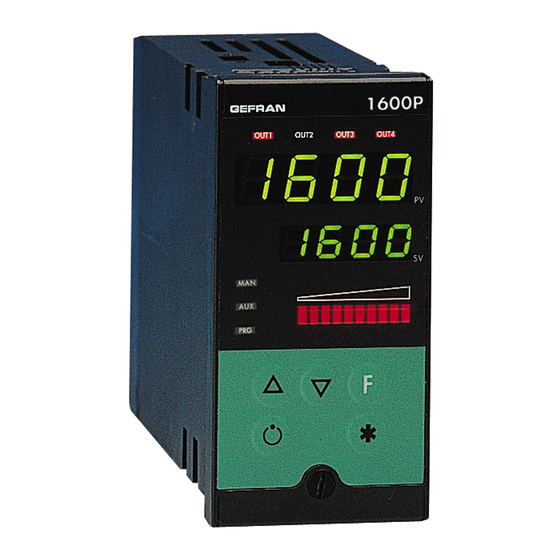
1600P / 1800P
CONTROLLER / PROGRAMMER
70
115
92
44,5
115
115
92
For correct and safe
installation, follow the
instructions and observe
the warnings contained in
this manual.
Panel mounting:
INSTALLATION AND
OPERATION MANUAL
SOFTWARE VERSION 3.2x
code 80090G / Edit 14 - 04-2013
2 • TECHNICAL SPECIFICATIONS
Display
Keys
Accuracy
Main input
Thermocouples
Cold junction error
RTD type (scale configurable within indicated
range, with or without decimal point)
PTC type (on request)
Max line resistance for RTD
Safety
°C / °F selection
Linear scale ranges
Controls
pb / dt / di
Action
Control outputs
Cycle time
Main output type
Softstart
Maximum power limit heat / cool
Fault power setting
Automatic blanking
Configurable alarms
Alarm masking
Type of relay contact
!
Logic output for static relays
Remote setpoint or
ammeter input (options)
CT scale range
Transmitter power supply (optional)
Analogue retransmission signal (opt)
Logic inputs (optional)
Serial interface (optional)
Baud rate
Protocol
Power supply (switching type)
Faceplate protection
Working / Storage temperature range
Relative humidity
Environmental conditions of use
Installation
Weight
EMC conformity has been tested with the following connections
FUNCTION
Power supply cable
Relay output cable
Digital communication wires
C.T. connection cable
TC input
Pt100 input
2 x 4 digits, green, height 10 and 7mm (1600P), 20 and 30 mm (1800P)
5 mechanical keys (
, Man/Auto, INC, DEC, F)
≠
0.2% full scale at 25°C room temperature
TC, RTD (Pt100 - JPT100), PTC,
50mV Ri ≥ 1MΩ; 10V Ri ≥ 10KΩ; 20mA, Ri = 50Ω
IEC 584-1
(J, K, R, S, T, B, E, N, Ni-Ni18Mo, L NiCr-CuNi)
0,1° / °C
DIN 43760 (Pt100, JPT100)
990Ω, 25°C
20Ω
detection of short-circuit or opening of probes,
LBA alarm, HB alarm
configurable from faceplate
-1999 to 9999 with configurable decimal point position
PID, Self-tuning, on-off
0.0 ... 999.9% / 0.00 ... 99.99min / 0.00 ... 99.99min
Heat / Cool
on / off, pwm
0.1 ... 200 sec
Relay, Logic, Continuous (optional)
0.0 ... 500.0 min
0.0 ... 100.0 %
-100.0 ... 100.0 %
Optional exclusion, displays PV value
3 configurable alarms type: max, min, symmetrical,
absolute or relative, LBA, HB
- exclusion during warm up
- latching reset from faceplate or external contact
NO (NC), 5A, 250V, cosϕ = 1
11Vdc, Rout = 220Ω (6V/20mA)
0 ... 10V, 2 ... 10V, Ri ≥ 1MΩ
0 ... 20mA, 4 ... 20mA, Ri = 5Ω
Potentiometer > 500Ω,
TA 50mAac, 50/60Hz, Ri = 1,5Ω,
isolation 1500V
configurable 0, ... , 100.0A
filtered 10 / 24Vdc, max 30mA
short-circuit protection, isolation 1500V
10V / 20mA, isolation 1500V
24V NPN, 4.5mA; 24V PNP, 3.6mA isolation 1500V
CL; RS422/485; RS232; isolation 1500V
1200 ... 19200
GEFRAN / MODBUS
(std) 100 ... 240Vac/dc ±10%; 50/60Hz, 12VA max
(opz.) 20...27Vac/dc ±10%; 50/60Hz, 12VA max
IP65
0...50°C / -20...70°C
20 ... 85% non-condensing
for internal use only, altitude up to 2000m
Panel, plug-in from front
400g (1600P); 600g (1800P) complete version
CABLE TYPE
LENGTH
1 mm
1 m
2
1 mm
3,5 m
2
0,35 mm
3,5 m
2
1,5 mm
3,5 m
2
0,8 mm
compensated
5 m
2
1 mm
3 m
2
1
Advertisement
Table of Contents

Subscribe to Our Youtube Channel
Related Manuals for gefran 1600P


Summary of Contents for gefran 1600P
- Page 1 80090G / Edit 14 - 04-2013 2 • TECHNICAL SPECIFICATIONS 1 • INSTALLATION Display 2 x 4 digits, green, height 10 and 7mm (1600P), 20 and 30 mm (1800P) • Dimensions and cut-out; panel mounting Keys 5 mechanical keys ( , Man/Auto, INC, DEC, F) ≠...
- Page 2 3 • DESCRIPTION OF FACEPLATE Indication of output states OUT 1 (Main); OUT 2 (AL 1); Function indicator OUT 3 (AL 2); OUT 4 (HB) Indicates modes of operation MAN = OFF (Automatic control) PV Display: Indication of process variable MAN = ON (Manual control) Error Indication: LO, HI, Sbr, Err AUX = ON (program in reset)
-
Page 3: Programming And Configuration
Unit layout SERIAL / W BOARD SERIAL / W BOARD CPU BOARD BOARD POWER POWER BOARD BOARD DISPLAY DISPLAY BOARD BOARD 5 • PROGRAMMING and CONFIGURATION INFO LEVEL 1 MENU Information display Press for dAtA Custom menu approx. Process variable (PV display) 2 sec P.V. - Page 4 • InFo Display Eu.r Event 1 Event 2 Event 3 Event 4 Eu.S Software “S” step ramp Information eu. r INFO prot protection events display code Serial Self diagnostic (ode er. n r communication error code code eu. s “S” step hold events No Error Software...
- Page 5 Proportional band for c Pb cooling or hysteresis for 0 ... 999.9% f.s. Proportional band for 0.0 ... 999.9% ON/OFF control c pb cooling or hysteresis on full scale ON-OFF action Integral time c It 0.00 ... 99.99 min for cooling Integral time c it 0.00 ...
- Page 6 485 / 232 2400 485 / 232 4800 485 / 232 SEr.P Serial protocol 9600 485 / 232 Serial interface ser. p CENCAL GEFRAN 19200 485 / 232 protocol MODBUS RTU CENCAL, MODBUS _PAr Parity Parity selection No parity (MODBUS only) Even •...
- Page 7 • Out Digital filter filt Output settings 0.0 ... 20.0 sec on main input Select AL.1.r, AL.2.r, AL.3.r al. i . r reference fild AL.x.r Variable to compare Alarm setpoint Digital filter on display 0 ... 9.9 signal for PV (Process variable) process variable: scale points alarm 1...
- Page 8 • Hrd Cycle time for OUT1 relay or 1..200 sec (t. 1 logic output = HEAT or COOL (0.1...20.0 sec) Hardware configuration Cycle time for OUT2 relay or (t. 2 SP.Pt Type of programmer 1..200 sec logic output = HEAT or COOL Programmer disabled (with programmer disabled, Programmer...
- Page 9 from enabled digital input Start/Stop from AL1 ON Function of “MAN” LEDs: M/A, L/R, ATUN, IN1, IN2 repetition, s. s . t . Programmer led. 1 from AL2 ON event programmer, serial port enabled, errors present (0...63) from AL3 ON LEd.1 (MAN), LEd.2 (AUX), LEd.3 (PRG) from serial line (address 0049H, bit 0) Reset...
-
Page 10: Using The Programmer
6 • PROGRAMMER The unit combines the functions of a single loop controller and programmer. The programmer function lets you run a program as a series of steps, each of which has two segments: √ a ramp √ a hold. Every step has its associated data: •... - Page 11 In this mode, the maximum duration of a step is 30 seconds In fast simulation mode, hold back band (Hbb) is inhibited, and control output takes on FAc.P value. All other functions enabled (type of restart, start/stop, reset, manual/automatic, end of cycle or continuous cycle, event outputs, clearance from digital inputs, slave channel setpoint, etc.) are active.
- Page 12 9 • ALARMS Normal absolute alarm Symmetrical absolute alarm AL1 + [ Hyst1 ] AL2 + Hyst2 AL1 + Hyst1 AL1 - [ Hyst1 ] time time alarm 1 Lo alarm Hi alarm alarm 2 For AL1 = reverse absolute alarm (low) with positive Hyst1, AL1 t = 1 For AL1 = symmetrical Lo absolute alarm with Hyst1, AL1 t = 5 (*) = OFF if disabled on power-up For AL1 = symmetrical Hi absolute alarm with Hyst1, AL1 t = 4...
-
Page 13: Control Actions
If the Integral Time value is too long (Weak integral action), deviation between the controlled variable and the setpoint may persist. Contact GEFRAN for more information on control actions. 12 • MANUAL TUNING A) Enter the setpoint at its working value. -
Page 14: Self-Tuning
14 • SELF-TUNING The function works for single output systems (heating or cooling). The self-tuning action calculates optimum control parameter values during process startup. The variable (for example, temperature) must be that assumed at zero power (room temperature). The controller supplies maximum power until an intermediate value between starting value and setpoint is reached, after which it zeros power. PID parameters are calculated by measuring overshoot and the time needed to reach peak. -
Page 15: Order Code
1.0 % OUT = 50mAac • Interface for GEFRAN instrument configuration Kit for PC via the USB port (Windows environment) for GEFRAN instruments configuration: KIT PC USB / RS485 o TTL Lets you read or write all of the parameters •... -
Page 16: Power Supply
VDE standards (class x2) and support at least 220 VAC. Resistors must be at least 2W); fit a 1N4007 diode in parallel with the coil of inductive loads that operate in DC. GEFRAN spa will not be held liable for any injury to persons and/or damage to property deriving from tampering, from any incorrect or erroneous use, or from any use not conforming to the device specifications.
Need help?
Do you have a question about the 1600P and is the answer not in the manual?
Questions and answers