
Related Manuals for Elba 345-004


Summary of Contents for Elba 345-004
- Page 1 TOUCH CONTROL INDUCTION COOKING HOBS Instructions for the use - Installation advices KEEP IN A SAFE PLACE Before operating this cooking hob, please read these instructions carefully Cod. 1104107-ß2...
-
Page 2: Declaration Of Ce Conformity
Dear Customer, Thank you for having purchased and given your preferen- ce to our product. The safety precautions and recommendations reported below are for your own safety and that of others. They will also provide a means by which to make full use of the fea- tures offered by your appliance. -
Page 3: Before Using For The First Time
BEFORE USING FOR THE FIRST TIME • Read the instructions carefully before installing and using the appliance. • After unpacking the appliance, make sure it is not damaged. In case of doubt, do not use the appliance and contact your supplier or a qualified engineer. •... - Page 4 • Do not place or leave empty pans on the glass ceramic hob. • Metallic objects such as knives, forks, spoons and lids should not be placed on the hob surface since they can get hot. • Do not use metallic kitchen utensils (e.g. ladles). It is preferable to use plastic or wood kitchen utensils.
-
Page 5: Features And Technical Data
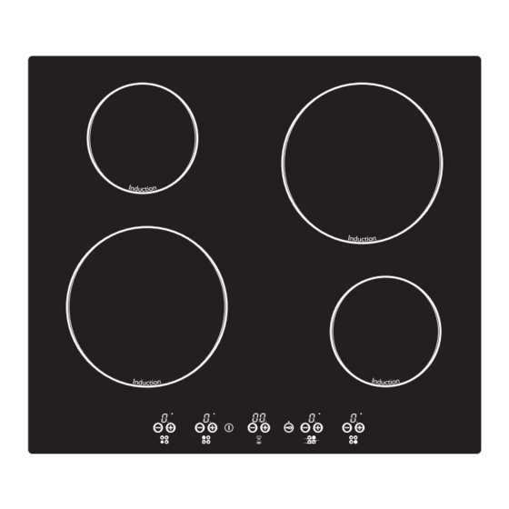
FEATURES AND TECHNICAL DATA Electrical insulation Class I COOKING ZONES Induction cooking zone Ø 145 mm - 1200 W (1600 W with Booster function) Induction cooking zone Ø 210 mm - 1500 W (2000 W with Booster function) TOUCH-CONTROL DESCRIPTION Front left zone keys (increasing and decreasing power) Rear left zone keys (increasing and decreasing power) Rear right zone keys (increasing and decreasing power) -
Page 6: Use Of Induction Hob
USE OF INDUCTION HOB Notes: • Each selection (by pressing one of the keys) is indicated by an acoustic signal (beep). • User interface initial calibration: this feature is for the keyboard calibration, to adapt the sensibility of the keys to the final mechanical, environmental and user conditions. -
Page 7: Thermal Protection
THERMAL PROTECTION The induction cooktop is fitted with safety devices to protect the electronic system and each cooking zone from overheating. OVERHEATING OF COOKING ZONE • Cooking zone OFF: the cooking zone display shows “ ” and “ ” alternating or just “... - Page 8 The ceramic cooktop is fitted with induction cooking zones. These zones, shown by painted disks on the ceramic surface, are controlled by a touch control system. INDUCTION COOKING SYSTEM When your induction hob is switched on and a cooking zone has been selected, the elec- tronic circuits produce induced currents that instantaneously heat the bottom of the pan which then transfers this heat to the food.
- Page 9 TURN TOUCH CONTROL ON AND OFF Switching ON Press the key and keep it pressed until the touch control is lighted. The displays of the cooking zones read “ ”. Notes: • If the safety key-lock protection is ac- tive, the touch control can be turned ON only after having deactivated this protection.
- Page 10 POWER IGNITION ADJUSTMENT OF A COOKING ZONE To turn ON a cooking zone the touch control must be switched ON (see sec- tion “HOW TO TURN THE TOUCH CONTROL ON AND OFF”). Press the key and keep it pressed until the desired power level, ranging between “...
-
Page 11: Booster Function
BOOSTER FUNCTION This function allows the cooking zone to operate at the Booster maximum power (above the nominal power) for maximum 10 minutes; it could be used, for example, to rapidly heat up large amount of water. To activate the Booster function, the touch control must be switched ON (see section “How to Turn the Touch Control ON and OFF”). - Page 12 SAFETY KEY-LOCK TO PROTECT CHILDREN This function locks the touch-control keys against unwanted activation. To activate the key-lock press the key the indicator light above the key symbol will light up for a few seconds. Then, if pres- sing any function key, the light above the key-lock symbol will light up again for a few seconds to indicate that the safety key-lock is active.
- Page 13 PROGRAM AUTOMATIC SWITCHING OFF OF ONE COOKING ZONE This function permits to set a timer from “ ” ” minutes for automatic turning OFF to “ of one cooking zone only. Note: It is not possible to set this program for all the cooking zones.
- Page 14 OPERATION TIME LIMIT OF COO- Power level of Operation KING ZONES Cooking zones time limit Each cooking zone automatically 10 hours switched OFF after a maximum preset time if no operation is performed. The maximum preset time limit depends 10 hours on the set power level, as illustrated in this schedule.
- Page 15 MAXIMUM POWER MANAGEMENT The cooktop maximum power limit (7200 W) can be reduced to 2800 W, 3500 W, or 6000 W. To change the maximum power limit: • Connect the appliance to the electrical power supply. • With the safety key-lock protection deactivated and all the cooking zones off, press at the same time the keys controlling the front cooking zones.
- Page 16 ERROR CODE ON THE DISPLAY/S If an error message appears on the display/s (the display/s show/s “ ” and another character alternating - e.g. “ ” and “ ”, “ ” and “ ”, ..) : Disconnect the cooktop from the mains.
-
Page 17: Cleaning And Maintenance
CLEANING AND MAINTENANCE CLEANING THE CERAMIC HOB Before you begin cleaning, disconnect the cooktop from mains power supply. • Remove spillages and other types of incrustations. • Dust or food particles can be removed with a damp cloth. • If you use a detergent, please make sure that it is not abrasive or scouring. Abrasive or scouring powders can damage the glass surface of the hob. -
Page 18: Installation
Advice for the installer INSTALLATION IMPORTANT : • This appliance shall only be serviced by authorized personnel. This appliance is to be installed only by an authorised person according to the • current local regulations and in observation of the manufacturer’s instructions. Incorrect installation, for which the manufacturer accepts no responsibility, may •... - Page 19 This cooktop can be built into a wor- king surface 30 to 50 mm thick and 600 mm deep. In order to install the ceramic hob into the kitchen fixture, a hole with the di- mensions shown in figure 4.1 has to be made, keeping in consideration the following: •...
-
Page 20: Fastening The Cooktop
FASTENING THE COOKTOP Each cooktop is supplied with a set of tabs and screws to fasten it on units with a working surface from 3 to 5 cm deep. The kit includes 4 tabs “A” and 4 self-threading screws “B” (figs. 4.4, 4.4a, 4.4b). •... -
Page 21: Electrical Connection
ELECTRICAL CONNECTION IMPORTANT: Installation must be carried out according to the manufacturer’s in- structions. Incorrect installation may cause harm and damage to people, animals or property, for which the manufacturer accepts no responsibility. Before carrying out any work on the electrical section of the appliance, it must be disconnected from the mains. - Page 22 CONNECTING THE FEEDER CABLE To connect the feeder cable to the hob it is necessary to carry out the following operations: • Unhook the terminal board cover “A” by inserting a screwdriver into the two hooks “B” (fig. 5.1). • Unscrew the screw “C”...
- Page 23 Fig. 5.1 230-240 V ac Green - Yellow Brown 230...240 V ac Blue 230-240 V ac Green - Yellow 400-415 V 2N ac Brown Green - Yellow 230-240 V ac 230...240 V ac Black Brown Blue Green - Yellow 230...240 V ac Brown Blue Fig.
- Page 24 The manufacturer cannot be held responsible for possible inaccuracies due to printing or transcription errors in the present booklet. The manufacturer reserves the right to make all modifications to its products deemed necessary for manufacture or commercial reasons at any moment and without prior notice, without jeopardising the essential functional and safety characteristics of the appliances.
Need help?
Do you have a question about the 345-004 and is the answer not in the manual?
Questions and answers