
Subscribe to Our Youtube Channel
Related Manuals for Elba 6E EX 397 I


Summary of Contents for Elba 6E EX 397 I
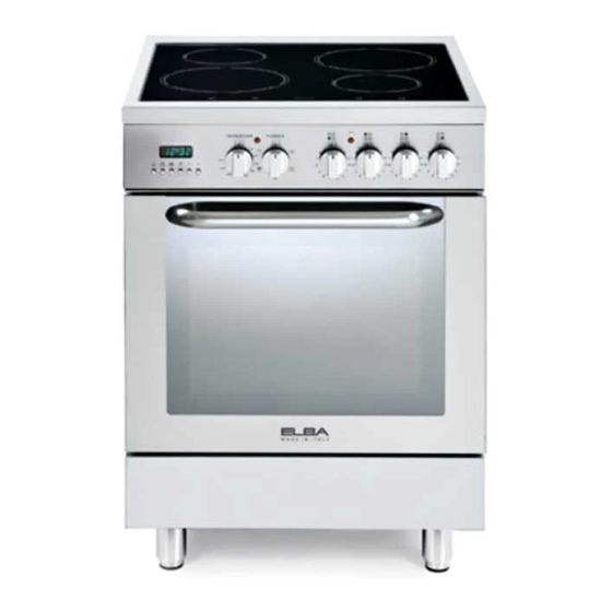
- Page 1 Instructions for the use - Installation advices VITROCERAMIC COOKER (INDUCTION HOB) ELBA QUALITY MADE IN ITALY Made in Italy...
- Page 3 Dear Customer, Thank you for having purchased and given your preference to our product. The safety precautions and recommendations reported below are for your own safety and that of others. They will also provide a means by which to make full use of the features offered by your appliance.
-
Page 4: Important Safety Precautions And Recommendations
IMPORTANT SAFETY PRECAUTIONS AND RECOMMENDATIONS IMPORTANT: This appliance is designed and manufactured solely for the cooking of domestic (household) food and is not suitable for any non domestic application and therefore should not be used in a commercial environment. The appliance guarantee will be void if the appliance is used within a non domestic environment i.e. - Page 5 • Do not touch the appliance with wet or damp hands (or feet). • Do not use the appliance whilst in bare feet • If you should decide not to use this appliance any longer (or decide to substitute another model), before disposing of it, it is recommended that it be made inoperative in an appropriate manner in accordance to health and environmental protection regulations, ensuring in particular that all potentially hazardous parts be made...
- Page 6 • WARNING: Danger of fire: do not store items on the cooking surfaces. • Do not place or leave empty pans on the glass ceramic hob. • Do not allow heavy or sharp objects to drop on the glass ceramic hob.
- Page 7 • Clean the oven regularly and do not allow fat or oils to build up in the oven base or tray. Remove spillages as soon as they occur. • Do not stand on the cooker or on the open oven door. • Always stand back from the appliance when opening the oven door to allow steam and hot air to escape before removing the food.
-
Page 8: Cooking Hob
COOKING HOB Fig. 1.1 INDUCTION COOKING HOB 1. Induction cooking zone Ø 145 mm Normal Power: 1200 W Booster Power: 1600 W 2. Induction cooking zone Ø 210 mm Normal Power: 1500 W Booster Power: 2000 W 3. Cooking zones display Note: The Nominal and Booster Power may change depending on the size and material of the pan set on the cooking zone. -
Page 9: Control Panel
CONTROL PANEL Fig. 2.1 CONTROLS DESCRIPTION Front right cooking zone control knob Rear right cooking zone control knob Rear left cooking zone control knob Front left cooking zone control knob Multifunction oven temperature control knob Multifunction oven function selector control knob Electronic clock/programmer Oven temperature indicator light Note:... -
Page 10: Use Of Induction Hob
USE OF INDUCTION HOB The ceramic hob is fitted with induction cooking zones. These zones, shown by painted disks on the ceramic surface, are controlled by separate knobs positioned on the control panel. On the front of the hob, the displays for each cooking zone indicate: Cooking zone Off (not activated). - Page 11 COOKWARE/COFFEE POT FOR INDUCTION COOKING The induction cooking system OPERATES ONLY if using correct cookware suitable for induction cooking (normally identified by an induction symbol on the bottom of the cookware/ coffee pot). The use of not suitable cookware may cause damage to the appliance. The bottom of the pan/coffee pot has to be ferromagnetic to generate the electromagnetic field necessary for the heating process (meaning a magnet has to stick to the bottom of the pan/coffee pot).
-
Page 12: Control Knobs
CONTROL KNOBS Each cooking zone is adjusted by a separate control knob positioned on the control panel and the operation is controlled by the electronic system. If a cooking zone is not turned Off the electronic system automatically switches it Off after a pre-set time which depends on the power setting. - Page 13 Ø 145 mm Ø 210 mm Cooking zone Watt Watt power level power power 75 W 100 W 150 W 200 W 300 W 300 W 400 W 500 W 500 W 700 W 600 W 900 W 800 W 1100 W 1000 W 1300 W...
- Page 14 OPERATION TIME LIMIT OF Power level of Operation COOKING ZONES Cooking zones time limit Each cooking zone automatically 10 hours switched Off after a maximum preset time if no operation is performed. The maximum preset time limit depends 5 hours on the set power level, as illustrated in this schedule.
- Page 15 MAXIMUM POWER MANAGEMENT The cooktop maximum power limit (7200 W) can be reduced to 6000 W, 3500 W, or 2800 W. To change the maximum power limit: • Before connecting the cooker to the mains electricity supply, turn all cooking zone control knobs to “8”.
- Page 16 MANAGING POWER WHILE USING THE HOB When using several cooking zones, if the total power set in the zones is greater than the maximum power limit for the hob, an audible alert (beep) will sound and the last cooking zone set will show “ ”...
-
Page 17: Thermal Protection
THERMAL PROTECTION The induction cooktop is fitted with safety devices to protect the electronic system and each cooking zone from overheating. OVERHEATING OF THE DISPLAY Cooking zone OFF: the cooking zone • display shows “ ” and “ ” alternating. Cooking zone ON: all zones are •... - Page 18 ERROR CODE ON THE DISPLAY/S If an error message appears on the display/s (the display/s show/s “ ” and another character alternating - e.g. “ ” and “ ”, “ ” and “ ”, ..) : Disconnect the cooktop from the mains.
-
Page 19: Cleaning The Ceramic Hob
CLEANING THE CERAMIC HOB Before you begin cleaning, disconnect the cooktop from mains power supply. • Remove spillages and other types of incrustations. • Dust or food particles can be removed with a damp cloth. • If you use a detergent, please make sure that it is not abrasive or scouring. Abrasive or scouring powders can damage the glass surface of the hob. -
Page 20: Multifunction Oven
MULTIFUNCTION OVEN OPERATING PRINCIPLES Attention: The oven door becomes Heating cooking very hot during operation. MULTIFUNCTION oven are obtained in the Keep children away. following ways: Models with lid: the cooker lid must be by normal convection kept open when the oven/grill is in use. The heat is produced by the upper and lower heating elements. -
Page 21: Thermostat Knob
Fig. 4.1 Fig. 4.2 THERMOSTAT KNOB (fig. 4.2) To turn on the heating elements of the oven, set the function selector knob on the desired program and the thermostat knob onto the desired temperature. To set the temperature, it is necessary to make the knob indicator meet the chosen number. The elements will turn ON or OFF automatically according to the energy need which is determined by the thermostat. -
Page 22: Defrosting Frozen Foods
GRILLING The infra-red heating element is switched on. The heat is diffused by radiation. Use with the oven door closed and with the thermostat knob to between 50 and 225°C. Note: It is recommended that you do not grill for longer than 30 minutes at any one time. Attention: the oven door becomes very hot during operation. -
Page 23: Cooking Advice
CONVECTION COOKING WITH VENTILATION The upper and lower heating elements and the fan turn on. The heat coming from the top and bottom is diffused by forced convection. The temperature must be regulated between 50°C and the maximum temperature with the thermostat knob. -
Page 24: Oven Cooking
GRILLING AND “AU GRATIN” COOKING EXAMPLES Temperatures are approximate as they vary Set the switch to position depending on the quality and amount of Set the thermostat to position 175°C and food. after having preheated the oven, simply Remember to use ovenproof dishes and to place the food on the shelf. -
Page 25: Electronic Programmer
ELECTRONIC PROGRAMMER The electronic programmer is a device which groups together the following functions: • 24 hours clock with illuminated display • Timer (up to 23 hours and 59 minutes) • Program for automatic oven cooking • Program for semi-automatic oven cooking Description of the buttons: Description illuminated... -
Page 26: Electronic Clock
ELECTRONIC CLOCK ELECTRONIC TIMER (fig. 5.2) The programmer is equipped with an The timer program consists only of a electronic clock with illuminated numbers buzzer which may be set for a maximum which indicates hours and minutes. period of 23 hours and 59 minutes. Upon immediate connection of the oven or If the AUTO symbol is flashing push the after a power cut, three zeros will flash on... -
Page 27: Automatic Oven Cooking
AUTOMATIC OVEN COOKING Set the temperature and the cooking program by using the switch and To cook food automatically in the oven, it is thermostat knobs of the oven (see necessary to: specific chapters). Set the length of the cooking period. oven programmed Set the end of the cooking time. -
Page 28: Semi-Automatic Cooking
SEMI-AUTOMATIC COOKING At the end of the cooking time the oven This is used to automatically switch off the oven after the desired cooking time has will turn off automatically, the symbol elapsed. will turn off, AUTO will flash and a buzzer will be sound, which can be turned off by There are two ways to set your oven: pushing any of the buttons except the... -
Page 29: Cleaning And Maintenance
CLEANING AND MAINTENANCE GENERAL ADVICE ENAMELLED PARTS • Before you begin cleaning, you All the enamelled parts must be cleaned must ensure that the appliance is with a sponge and soapy water or other disconnected from the electrical non-abrasive products. power supply. - Page 30 INSIDE OF OVEN The oven should always be cleaned after use when it has cooled down. The cavity should be cleaned using a mild detergent solution and warm water. Suitable proprietary chemical cleaners may be used after first consulting with the manufacturers recommendations and testing a small sample of the oven cavity.
-
Page 31: Important Warning
REPLACING OVEN LAMP REPLACING OVEN LAMP (MODELS WITH INCANDESCENT (MODELS WITH HALOGEN LAMP) LAMP) WARNING: Ensure the appliance is switched off and disconnected from the WARNING: Ensure the appliance is electrical power supply before replacing switched off and disconnected from the the lamp to avoid the possibility of electrical power supply before replacing electric shock. -
Page 32: Removing The Oven Door
REMOVING THE OVEN DOOR The oven door can easily be removed as follows: • Open the door to the full extent (fig. 6.6). • Open the lever “A” completely on the left and right hinges (fig. 6.7). • Hold the door as shown in fig. 6.9. •... - Page 33 CLEANING THE PANES OF GLASS The oven door is fitted with no. 2 panes: • no. 1 outside; • no. 1 inner; To clean the panes on both sides it is necessary to remove the inner pane as follows. Do not use harsh abrasive cleaners or sharp metal scrapers to clean the oven door glass since they scratch the surface, which may result in shattering...
- Page 34 REPLACING THE INNER PANE OF GLASS Make sure the door is locked open (see fig. 6.8). Replace the inner pane: • Check that the four rubber pads are in place (“D” in fig. 6.13). Fig. 6.13 • Insert the pane in the left “E” and right “F”...
- Page 35 Advice for the installer IMPORTANT • Cooker installation must only be carried out by QUALIFIED TECHNICIANS and in compliance with local safety standards. Failure to install the appliance correctly could invalidate any manufacturer’s warranty. • The appliance must be installed in compliance with regulations in force in your country and in observation of the manufacturer’s instructions.
-
Page 36: Installation
INSTALLATION The installation conditions, concerning protection against overheating of the surfaces adjacent to the cooker, must conform to fig. 7.1. The appliance must be kept no less than 50 mm away from any side wall which exceeds the height of the hob surface (fig. 7.1). The appliance must be housed in heat resistant units. -
Page 37: Levelling The Cooker
FITTING THE ADJUSTABLE FEET AND LEVELLING THE COOKER The adjustable feet must be fitted to the base of the cooker before use (fig. 7.2). Rest the rear of the cooker on a piece of the polystyrene packaging exposing the base for the fitting of the feet. Fit the 4 legs by screwing them tight into the support base as shown in figure 7.2. -
Page 38: Moving The Cooker
MOVING THE COOKER WARNING: When raising cooker to upright position always ensure two people carry out this manoeuvre to prevent damage to the adjustable feet (fig. 7.5). WARNING Be carefull: do not lift the cooker by the door handle when raising to the upright position (fig. 7.6). -
Page 39: Anti-Tilt Bracket
ANTI-TILT BRACKET Warning: This appliance must be restrained to prevent accidental tipping by fitting a bracket to the rear of the appliance and securely fixing it to the wall. To fit the anti-tilt bracket: After you have located where the cooker is to be positioned, mark on the wall the place where the 2 screws of the anti-tilt bracket have to be fitted. Please follow the indications given in fig. -
Page 40: Electrical Section
ELECTRICAL SECTION N.B. For connection to the mains, do IMPORTANT: The cooker must be not use adapters, reducers or branching installed accordance with devices as they can cause overheating manufacturer’s instructions. and burning. Incorrect installation, which manufacturer accepts If the installation requires alterations to the responsibility, may cause damage to domestic electrical system, call an expert. -
Page 41: Connection Of The Power Supply Cable
CONNECTION OF THE POWER SUPPLY CABLE Important! This cooktop must be connected to the electricity supply only by an authorised person. To connect the feeder cable to the hob it is necessary to carry out the following operations: • Unhook the terminal board cover “A” by inserting a screwdriver into the two hooks “B” (fig. - Page 42 Fig. 8.2 220 - 240 V~ N (L 380 - 415 V 2N~ 380 - 415 V 3N~ Fig. 8.3...
- Page 44 The manufacturer reserves the right to make all modifications to its products deemed necessary for manufacturer commercial reasons at any moment and without prior notice, without jeopardising the essential functional and safety characteristics of the appliances. www.elba-cookers.it Made in Italy Cod. 1105237 - ß0...
Need help?
Do you have a question about the 6E EX 397 I and is the answer not in the manual?
Questions and answers