Elba P60 Installation And Instruction Manual
Hide thumbs
Also See for P60:
- Instructions for the use - installation advices (21 pages) ,
- Instruction for the use - installation advice (68 pages) ,
- Instructions for use manual (57 pages)
Table of Contents
Advertisement
Quick Links
Advertisement
Table of Contents

Related Manuals for Elba P60


Summary of Contents for Elba P60
- Page 1 BUILT-IN GAS HOBS P 6 0 INSTRUCTION FOR THE USE INSTALLATION ADVICE...
- Page 2 Dear Customer, Thank you for having purchased and given your preference to our product. The safety precautions and recommendations reported below are for your own safety and that of others. They will also provide a means by which to make full use of the features offered by your appliance. Please preserve this booklet carefully.
-
Page 3: Important Precautions And Recommendations
IMPORTANT PRECAUTIONS TIPS FOR THE USER AND RECOMMENDATIONS During and after use of the cook- top, certain parts will become very After having unpacked the appli- hot. Do not touch hot parts. ance, check to ensure that it is not damaged. - Page 4 COOKING HOB FEATURES Fig. 1.1 Fig. 1.2 Fig. 1.3 Fig. 1.4 Fig. 1.5...
-
Page 5: Control Panel Description
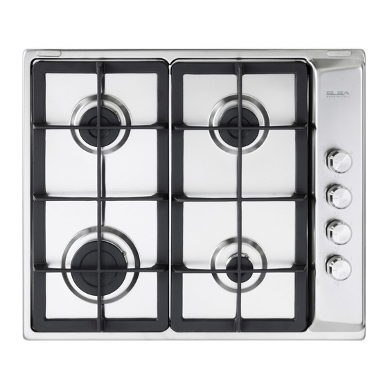
COOKING SPOTS 1. Auxiliary burner (A) - 1.00 kW 2. Triple-ring burner (TR) - 3.50 kW 3. Semirapid burner (SR) - 1.75 kW (left) 4. Semirapid burner (SR) - 1.75 kW (right) 5. Rapid burner (R) - 3.00 kW 6. Electric hotplate Ø 145 - normal - (1000 W) - rapid - (red dot 1500 W) 7. -
Page 6: Gas Burners
USE OF COOKING HOBS GAS BURNERS The gas flow to the burners is achieved by turning the knob (illustrated in fig. 2.1) which controls the safety tap. By turning the knob so that the indicator line points at the symbols printed on the panel we obtain the following settings: full circle = closed valve... - Page 7 (models with safety valve device) The ignition device shall not be operated for more than 15 seconds. In order to light the burner, you must: If after 15 seconds the burner has 1 – Turn the knob fig. 2.2 in anti-clock- not lit, stop operating the device wise direction up to the maximum and open the compartment door of...
-
Page 8: Choice Of Burner
CHOICE OF BURNER It is important that the diameter of the pots or pans suitably match the heating On the control panel, near every knob, potential of the burners in order not to there is a diagram that indicates which jeopardise the efficiency of the burners, burner is controlled by that knob. -
Page 9: Correct Use Of Triple-Ring Burner
GRILL FOR SMALL COOKWARE (optional) (fig. 2.4) Put it on the auxiliary burner (the small- est) grid when small cookware is being used to prevent the cookware from tip- ping over. Fig. 2.4 CORRECT USE OF TRIPLE-RING BURNER The flat-bottomed pans are to be placed directly onto the pan-support. To use the WOK you need to place the proper stand in order to avoid any faulty operation of the triple-ring burner (Figs. -
Page 10: Electric Hotplates
ELECTRIC HOTPLATES NORMAL HOTPLATE RAPID HOTPLATE (red dot) To turn on the electric hotplate, rotate The rapid hotplate control knob is similar the knob (fig. 2.6) to the desired setting. to that of the normal hotplate, with 6 The numbers from 1 to 6 indicate the selectable heating positions (2.6). - Page 11 PROPER USE OF THE ELECTRIC Caution! HOTPLATE (fig. 2.7) the cooking hob becomes very hot during operation. When the pan comes to the boil, turn the Keep children well out of reach. heat down to the level desired. Remember that the hotplate will continue to produce heat for about five minutes after it has been turned off.
- Page 12 ELECTRIC HOTPLATE USAGE TABLE Position TYPE OF COOKING of switch Switched OFF For melting operations (butter, chocolate). To maintain food hot and to heat small quantities of liq- uid (sauces, eggs). To heat bigger quantities; to whip creams and sauces. (vegetables, fruits, soups).
-
Page 13: Cleaning And Maintenance
CLEANING AND MAINTENANCE CLEANING ELECTRIC HOTPLATES GENERAL RECOMANDATION Always clean when the hotplate is Before you begin cleaning you must tepid. ensure that the hob is switched off. Use a soft cloth, dampened with water, It is advisable to clean when the and a little salt. - Page 14 GLASS LID - optional INSTALLATION OF THE GLASS LID 1. Remove gently the 2 hole-cover plates (T) from the rear edge of the cooking hob, being careful not to chip the enamel (fig. 3.2). 2. Thread the 4 holes (H) with the screws (F) (fig. 3.1). Lubricate the screws with an oil drop to make easy the screwing.
- Page 15 SET THE CORRECT BALANCE CLEANING – Close the lid and check the correct – To clean, it is easy to remove the lid balance; if laid on 45° position it by pulling it upwards once it is fully should stay hanging. open.
- Page 16 BATTERY FOR ELECTRIC IGNITION (some models only) In some models the battery is the power supply for the electronic ignition of gas burners. Batteries last on average for about two years (alkaline battery) depending on how often the electronic ignition is used.
- Page 17 Important notes: FITTING THE BATTERY IGNITION SUPPLY Remove the battery if the cooking hob is not going to be used for a long Remove pan supports and burners time. from the cooktop. If the battery leaks, replace it immedi- Turn over the cooktop: be carefull to ately.
- Page 18 CORRECT REPLACEMENT OF THE BURNERS It is very important to check that the burner flame spreader F and the cap C have been correctly positioned (see figs. 3.8 and 3.9 ). Failure to do so can cause serious problems. Check that the electrode S (fig. 3.8) is always clean to ensure trouble-free sparking. In the models with safety device, check that the probe T (fig.
- Page 19 CORRECT POSITION OF TRIPLE RING BURNER The triple ring burner must be correctly positioned (see fig. 3.10); the burner rib must be fitted in their housing as shown by the arrow. Then position the cap A and the ring B (fig. 3.11 - 3.12). The burner correctly positioned must not rotate (fig.
-
Page 20: Installation
Advice for the Installer INSTALLATION IMPORTANT The appliance should be installed by a QUALIFIED INSTALLATION TECHNICIAN. The appliance must be installed in compliance with regulations in force in your country and in observation of the manufacturer's instructions. Always unplug the appliance before carrying out any maintenance operations or repairs. - Page 21 INSTALLATION OF THE COOKING The furniture walls adjacent to the cooking hob must be necessarily of material resistant to heat. The veneered synthetical material and the glue used must be resistant to a temperature of 120°C in order to avoid ungluings or deformations. To built-in the cooking hob it is neces- sary to cut out the working top according to the dimensions shown in the figures,...
- Page 22 FASTENING THE COOKER TOP FASTENING THE INSTALLATION BRACK- – Spread the sealing material “D” out Each cooker top is provided with an along the fixture hole, making sure installation kit including brackets and that the junctions overlap at the cor- screws for fastening the top to fixture ners.
- Page 23 CHOOSING SUITABLE DISCHARGING PRODUCTS OF SURROUNDINGS COMBUSTION In the room chosen to accommodate the Extractor hoods connected directly to gas appliance, there must be an ade- the outside must be provided, to allow quate natural draft to allow combustion of the products of combustion of the gas the gas.
-
Page 24: Gas Section
GAS SECTION TYPES OF GASES Gas connection for: The gases normally used may be Natural gas G20 or city gas G110 grouped, in view of their features, in three families: Remove the adaptor “C” using two spanners. - L.P.G. (in cylinders) - NATURAL GAS (methane) Connect the cooking hob to the gas - CITY GAS... - Page 25 ROTATION OF THE ELBOW IMPORTANT: Never attempt to turn the elbow The appliance is supplied with a gas “A” without having first slackened connection oriented towards the centre off the relative lock nipple. of the cooking hob. The connection to the gas supply must The gaskets “D-E-F”...
- Page 26 GAS MAINTENANCE ADAPTING THE APPLIANCE TO FUNC- OPERATIONS TO BE PERFORMED TION WITH DIFFERENT TYPES OF GAS WHEN SUBSTITUTING THE INJEC- TORS If a different gas from that one indicated on the label is used, you need to adapt the Remove the pan-supports, the burner cooktop to this new situation.
- Page 27 TABLE FOR THE CHOICE OF THE INJECTORS REDUCED NOMINAL TOWN GAS NATURAL GAS POWER POWER Ø injector Ø injector Ø injector [Hs - kW] [Hs - kW] [1/100 mm] [1/100 mm] [1/100 mm] BURNERS Auxiliary (A) 1,00 0,30 72 (X) 145 (1) Semi-rapid (SR) 1,75...
- Page 28 REGULATING THE BURNER MINIMUM LUBRICATING THE GAS TAPS SETTING If one of the gas taps becomes hard to turn, dismantle it, thoroughly clean with When switching from one type of gas to petrol and apply special high-tempera- another, the minimum flow rate must also ture grease.
-
Page 29: Electrical Section
ELECTRICAL SECTION N.B. For connections to the mains IMPORTANT: The cooking hob be power supply, never use adapters, installed in accordance with the reductions or multiple power points manufacturer’s instructions. as these may overheat and catch fire. Incorrect installation, for which the manufacturer accepts no responsi- In the event that installation should bility, may cause damage to per-... -
Page 30: Electrical Connection
GAS COOKING HOBS and COOKING HOBS WITH 4 ELECTRICAL GAS COOKING HOBS WITH 1 ELEC- PLATES TRICAL PLATE FEEDER SPECIAL CABLE SECTION ELECTRICAL CONNECTION Type “HO5V2V2-F” To connect the mains flex to the hob, resistant to temperatures of 90°C proceed as follows: Upturn the hob Models: Unscrew screws “A”... - Page 31 230 V 50 Hz 3 4 5 (L ) 400 V 3N 50 Hz 3 4 5 Fig. 6.3 400 V 2N 50 Hz 3 4 5 Fig. 6.4 Fig. 6.2...
- Page 32 The manufacturer cannot be held responsible for possible inaccuracies due to printing or transcription errors in the present booklet. The manufacturer reserves the right to make all modifications to its products deemed necessary for manufacture or commercial reasons at any moment and without prior notice, without jeopardising the essential functional and safe- ty characteristics of the appliances.
Need help?
Do you have a question about the P60 and is the answer not in the manual?
Questions and answers