Advertisement
P
L
ARTS
IST
quantity
description
1
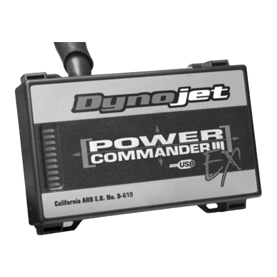
power commander EX
1
USB cable
1
cd-rom
1
installation guide
1
power adapter
2
power commander decal
2
dynojet decal
2
velcro strip
1
alcohol swab
1
wire tap
P
LEASE
D
OWNLOAD THE
Dynojet Research • 2191 Mendenhall Drive • North Las Vegas, NV 89081 • (800) 992-4993
i323-411EX
2005-2007 S
C90 B
I
NSTALLATION
R
A
D
EAD
LL
IRECTIONS
P
C
OWER
OMMANDER SOFTWARE AND LATEST MAPS FROM OUR WEBSITE
.
WWW
POWERCOMMANDER
UZUKI
OULEVARD
I
NSTRUCTIONS
expansion port
B
S
EFORE
TARTING
.
COM
USB port
I
NSTALLATION
:
2005-2007 Suzuki C90 - PCIII USB EX - 1
Advertisement
Table of Contents

Related Manuals for Dynojet POWER COMMANDER III USB EX


Summary of Contents for Dynojet POWER COMMANDER III USB EX
- Page 1 EFORE TARTING NSTALLATION OWNLOAD THE OWER OMMANDER SOFTWARE AND LATEST MAPS FROM OUR WEBSITE POWERCOMMANDER Dynojet Research • 2191 Mendenhall Drive • North Las Vegas, NV 89081 • (800) 992-4993 2005-2007 Suzuki C90 - PCIII USB EX - 1 i323-411EX...
- Page 2 The ignition must be turned OFF before installation. Remove the main seat and the passenger seat. remove these bolts Remove the center gauge cluster as shown in Figure A. Remove the right and left cosmetic covers as shown in Figure B. Remove the air box by loosening the two hose clamps and disconnecting the air box temp sensor harness.
- Page 3 Attach the orange wires from the PCIII USB EX to the stock wiring harness and front injector stock connector as shown in Figure D. PCIII USB EX connectors Attach the yellow wires from the PCIII USB EX PCIII USB EX to the stock wiring harness and rear injector as connectors shown in Figure E.
- Page 4 11 Crimp the supplied wire tap to the blue/black wire. 12 Attach the grey wire from the PCIII USB EX to the wire tap as shown in Figure G. Note: It is recommended to use dielectric wire tap grease on these connections. 13 Attach the TPS connector back to the throttle body.
Need help?
Do you have a question about the POWER COMMANDER III USB EX and is the answer not in the manual?
Questions and answers