
Related Manuals for AIC CB117-OT


Summary of Contents for AIC CB117-OT
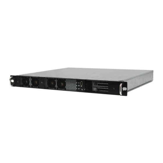
- Page 1 CB117-OT Computer Node Barebone User Manual Document Number: MAN-00111-A P/N: H881BB0W40-00000-0...
-
Page 2: Table Of Contents
Chapter 1. Product Introduction ............5 1.1. General Information ................5 1.2. System Specifications ................ 6 1.3. Front View of CB117-OT ..............8 1.4. Rear View of CB117-OT ..............8 1.5. Top View of CB117-OT ............... 9 Chapter 2. Hardware Setup ..............10 2.1. - Page 3 Updating BMC Configuration ............41 Chapter 6. Technical Support ............42 Copyright © 2012 AIC, Inc. All Rights Reserved. This document contains proprietary information about AIC products and is not to be disclosed or used except in accordance with applicable agreements.
-
Page 4: Safety Information
Safety Information When installing, operating, or performing maintenance on this equipment, basic safety precautions, as listed below, should always be followed to reduce the risk of fire, electric shock, and personal injuries. Read and understand all instructions. Observe warnings and instructions marked on the product. ... -
Page 5: About This User Manual
About This User Manual CB117-OT This document provides a detailed description of the including: The General Features of the Product Hardware Setup Motherboard Settings BIOS Configuration and Settings BMC Configuration and Settings ... -
Page 6: Chapter 1. Product Introduction
CB117-OT , a 1U Compute Node Barebone, supports Single socket C32 to support AMD® 4100/4200 series processor. CB117-OT has 2 x 2.5” internal HDD bays for flexible storage applications. CB117-OT harnesses MAX I/O™ technologyto support 1 OTS(off-the-shelf) PCIe card and 1 HTX card. -
Page 7: System Specifications
1.2. System Specifications Dimensions (with chassis ears/protrusions) mm : 484.9 x 382 x 44.4 W x D x H inches : 19 x 15 x 1.75 Motherboard Motherboard Octans (PSG-M-OCUP5690-101) Processor Processor Support Single socket C32 to support AMD 4100 /4200 series processor ®... - Page 8 Network 2 x Intel 82574L PCIe single-port GbE controllers ® Controllers Aspeed AST 2050 graphics controller Graphics • 8 MB of system memory • 1600 x 1200 @ 60 Hz Super I/O Nuvoton NCT6627UD (Winbond W83627UHG) Audio Codec REALTEK ALC662-GR Rear I/O 2 x RJ-45 ports 2 x USB 2.0 ports...
-
Page 9: Front View Of Cb117-Ot
1.3. Front View of CB117-OT System System Controls Icon Icon Color Behavior Behavior Solid: System On Push for Power On Power LED Green Power ON/OFF Off: System Off or Off System System ID Push for ID LED On Blue Identification... -
Page 10: Top View Of Cb117-Ot
1.5. Top View of CB117-OT The barebone server includes the basic components shown below. System Fans 2 x 2.5”HDD Octans Motherboard Rear IO Power Supply Expansion Slots... -
Page 11: Chapter 2. Hardware Setup
Chapter 2. Hardware Setup This section demonstrates maintenance procedures in replacing a defective part once the CB117-OT appliance is installed and is operational. 2.1. Chassis Cover 2.1.1 Removing the Chassis Cover 1. Release two thumbscrews from the rear panel and two screws from the top panel.. - Page 12 2.1.2 Central Processing Unit (CPU) 2.1.3 Installing the CPU Press the load lever to release the load plate. Load lever Lift the load plate. Load plate...
- Page 13 Remove the processor protective cover from CPU socket. Processor protective cover Align the processor cutouts against the socket notches. Cutouts Close the load plate & load lever. Press to close...
- Page 14 2.1.4 Installing the CPU Heatsink To install the CPU heatsink: 1. Place the heatsink on top of the CPU, ensuring that the two fasteners match the holes on the motherboard. 2. Tighten screws on each side of the heatsink, a couple of turns at a time, until all screws are secure and the heatsink is securely fastened to the chassis.
-
Page 15: System Memory
2.2. System Memory This server board supports up to six DDR3 800/1066/1333 /1600 Registered ECC SDRAM (recommended)/ Unbuffered ECC SDRAM. Populate DIMMs in the following order: RDIMM: DIMM DIMM arrangement Numbers 2 DIMMs DIMM2 DIMM2 4 DIMMs DIMM2 DIMM2 DIMM0 DIMM0 DIMM2 DIMM2... - Page 16 DIMM DIMM arrangement Numbers 2 DIMMs DIMM2 DIMM2 4 DIMMs DIMM2 DIMM2 DIMM0 DIMM0 2. Unlock a DIMM socket by pressing the retaining clips outward. 3. Insert module vertically and press down until it snaps into place. DIMM notch...
-
Page 17: Drive Bays
2.3. Drive Bays 2.3.1 Installing or Replacing 2.5” HDD Module 1. Unscrew the HDD canister and pull it out of the chassis. 2. Insert HDD to the corresponding place and screw both sides of HDD canister. - Page 18 Insert the HDD canister to the system and screw each side to fix it.
-
Page 19: 2.4. Riser Card
2.4. Riser Card RISER CARD PN (PSG CODE) DESCRIPTION (RC-PE1U15 Ver B) Max IO supports one PCIeX16 , one HTX. RISER CARD DIAGRAM Top view (Add-on card side) PCIE2 PCIE4 PCIE3 Bottom view (Add-on card side) Slot Bandwidth PCIE 2 PCIE 3、PCIE 4... -
Page 20: Expansion Slot
2.5. Expansion Slot 2.5.1 Installing an External Expansion Card to the Riser Card 1. Remove two screws to release the bracket. 2. To install a full length expansion card, please remove two brackets on the side. 3. Insert the full length card into the proper position. 4. -
Page 21: Chapter 3. Motherboard Settings
Chapter 3. Motherboard Settings This section describes the jumpers, internal connectors, and internal LEDs setting on Octans (PSG-M-OCUP5690-101) motherboard. We will show the motherboard layout and important jumper settings of the system. Motherboard Layout and Connectors Connectors Description 2. PWR BTN 1.PWR LED+ 4.GND 3.PWR LED#... - Page 22 Motherboard Layout and Connectors (Continued) Connectors Description 1.3.3V 2.GbE1 LED+ 3.3.3V Dual 4.GbE0 LED+ 5.NC 6.NC LAN LED LED ON = LINK LED BLINK = ACTIVE 1.FAN7_TACH 2.FAN8_TACH 3.SIO_FAN1_TACH 4.SIO_PWM1 5.SIO_FAN2_TACH 6.SIO_PWM2 SIO FAN CONN 7.SIO_FAN3_TACH 8.SIO_PWM3 9.SIO_FAN4_TACH 10.SIO_PWM4 11.GND 12.GND...
- Page 23 Motherboard Layout and Connectors (Continued) Connectors Description 2.3.3V_DUAL 1.GND 4.I2CSDA 3.I2CSCL 6.FAN1_TACH 5.PWM1 8.FAN2_TACH 7.PWM2 AST FAN 10.FAN3_TACH 9.PWM3 12.FAN4_TACH 11.PWM4 14.FAN5_TACH 13.FAN6_TACH 16.GND 15.GND 2.GPIOC0 1.GND 4.GPIOC1 3.GPIOE7 BMC GPIO(1) 6.GPIOB2 5.GPIOE6 1.I2C1SDA 2.GND IPMB 3.I2C1SCL 4.NC 1.+5V_AUX 2.I2C_CLK PSU I2C 3.I2C_DATA 4.GND...
- Page 24 Motherboard Layout and Connectors (Continued) Connectors Description 1-2 DISABLE VGA Disable (Jumper) OFF ENABLE 1.KB_DATA 2.+5V_AUX 3.KB_CLK KB/MS 4.MS_CLK 5.MS_DATA 6.GND 1 ON: MASTER OFF: SLAVE HT3 MODE 2 OFF: MASTER ON: SLAVE 9.GPIO62 10.GPIO61 7.GPIO40 8.GPIO39 SP5100 GPIO 5.GPIO0 6.GPIO4 3.GPIO6 4.GPIO10...
- Page 25 Motherboard Layout and Connectors (Continued) Connectors Description 1.POWER_BTN 2.RESET_BTN 3.TX 4.RX 5.GND 1.Tx 2.Rx BMC DEBUG 3.GND 15.GND 16.CLK 13.GND 14.GND 11.V_SYNC 12.DVO_5V 9.NC 10.H_SYNC 7.GND 8.BLUE 5.DATA 6.GND 3.GREEN 4.NC 1.GND 2.RED 2.MIC2-L 1.GND 4.MIC2-R 3.PRESENSE# HD AUDIO 6.LINE-R 5.MIC2-JD 8.GND 7.NC...
- Page 26 Motherboard Layout and Connectors (Continued) Connectors Description 1-2 RESET BMC RESET (Jumper) OFF NORMAL 1-2 DISABLE BMC DISABLE (Jumper) OFF ENABLE 1.GPIOA4 BMC GPIO(2) 2.GPIOA5 3.GND 9.GND 10.NC 7.GND 8.GND 5.USBD+ 6.USBD+ 3.USBD- 4.USBD- 1.USB5V 2.USB5V 1.+5V SATA DOM POWER 2.GND 1.DSR# 2.DCD#...
-
Page 27: Leds
11.DBRDY3 12.CPU_RESET_L 13.DBRDY2 14. DBRDY0 15.DBRDY1 16.DBREQ_L 17.VSS 18.TEST19 19.VDDIO 20.TEST18 1-2 ENABLE CPU PRESENT (Jumper) OFF DISABLE LEDs 3.2.1 Front Panel LEDs Yellow System is On System is in Standbyl System is off, but has Power Blinking AC power System has no AC power Blue UID activity detected... - Page 28 3.2.3 Internal LEDs ON(Blinking) BMC activity detected HEART BIT BMC is not active AC in, standby power ready Standby Power LED AC off, Standby power off UID activity detected UID LED UID not activity detected...
-
Page 29: Chapter 4. Bios Configuration And Settings
Chapter 4. BIOS Configuration and Settings 4.1. BIOS Setting 1. Press DEL to run the setup procedure. 2. There will be a message “Entering SETUP” displayed on the diagnostics screen. - Page 30 3. Identify the BIOS Version 4. Load Optimal Default setting 5. Save the setting and exit the BIOS setup utility.
-
Page 31: Updating Bios
4.2. Updating BIOS Important Notes: 1. To identify the current BIOS version, please check out on BIOS setup. There are two methods to update the latest BIOS. 1. Update by Messiash Flash utility during POST 2. Update by AMI AFUDOS utility under DOS environment Update by Messiash Flash utility during POST 1. - Page 32 6. Please press <F> key to enter Messiah Flash utility. 7. Follow the instruction until the message “Update Flash successfully” that had been displayed. 8. Reboot system. Update by AMI AFUDOS utility under DOS environment If you need to update Flash in the DOS environment, please use AFUDOS utility. To use this utility, you must include the flash.bat , AFUDOS.exe, and rom file in the same folder.
-
Page 33: Chapter 5. Bmc Configuration And Settings
Chapter 5. BMC Configuration and Settings Insert Ethernet LAN cable into the BMC LAN port. There are two methods to setup BMC IP: BMC management port 5.1. Method 1 (Use the BIOS setup) BIOS SETUP -> Server Mgmt -> BMC network configuration... - Page 34 Set IP static. Input IP address.
-
Page 35: Method 2 (Use A Dos Tool - Syscheck)
Input subnet mask address. 5.2. Method 2 (Use a Dos tool - Syscheck) Type : sc –lanset. Modify IP setting. - Page 36 Input IP address. Input submask address. Below IP address is an example using a default IP setting. User is allowed to change the IP address for realistic use. Finish BMC IP configuration.
-
Page 37: Connect To Bmc
5.3. Connect to BMC Below IP address is an example using default IP setting. User is allowed to change the IP address for realistic use. Open the browser then type BMC IP address: 192.168.0.115... - Page 38 Use the default user name and password for first-time login to ASTER. Field: Default UserName root Password: superuser Information of ASTER firmware.
- Page 39 Server Health - Sensor Readings: Configuration Please refer to AIC BMC User Guide for more information on AIC BMC. Mouse Mode setting: For Windows OS environment, set mode to absolute. For Linux OS environment, set mode to relative.
- Page 40 Remote Control: Environmental setting: Press “ALT+M” for local and remote OS mouse control switching.
-
Page 41: Updating Bmc Firmware
3. Execute a.bat batch file to update the BMC firmware Example: A:>cd OCTAM010 A:\ OCTAM010>a.bat This is just an example. The latest BMC firmware version is available from the FAE or AIC website. After update BMC firmware, please power off and then power on system. -
Page 42: Updating Bmc Configuration
3. Execute the config.bat batch file to update config file Example: A :> cd CB117C10 A:\ CB117C10>config.bat This is just an example; the latest BMC configuration version is available from the FAE or AIC website. 4. After update config file, please power off and then power on system. -
Page 43: Chapter 6. Technical Support
Chapter 6. Technical Support www.aicipc.com TAIWAN Tel: +886.3.313.8386 Fax: +886.3.313.8377 Email Technical Support: support@aicipc.com JAPAN Tel: +81.43.202.8380 Fax: +81.43.202.8381 Email Technical Support: support@aicipc.com CHINA Tel: +021.54961421, +021.54961422 Fax: Extension: 608 Email Technical Support: support@aicipc.com AMERICA - West coast ... - Page 44 Note...
Need help?
Do you have a question about the CB117-OT and is the answer not in the manual?
Questions and answers