
Related Manuals for AIC GB109-CT


Summary of Contents for AIC GB109-CT
- Page 1 GB109-CT GB109-CT General Purpose Server Barebone General Purpose Server Barebone User’s Manual User’s Manual Document Number : MAN-00102-A Document Number : MAN-00102-A ...
-
Page 2: Table Of Contents
1.1 General Information ........................5 ........................5 1.2 System Specifications 1.2 System Specifications ......................6 ......................6 1.3 Front View of GB109-CT 1.3 Front View of GB109-CT ......................8 ......................8 1.4 Rear View of GB109-CT.................... 1.4 Rear View of GB109-CT.................... 1.5 Top View of GB109-CT 1.5 Top View of GB109-CT... - Page 3 Copyright © 2010 Advanced Industrial Computer .Inc. All Rights Reserved. Copyright © 2010 Advanced Industrial Computer .Inc. All Rights Reserved. This document contains proprietary information about AIC products and is not to This document contains proprietary information about AIC products and is not to be disclosed or used except in accordance with applicable agreements. ...
-
Page 4: Safety Information
Safety Information Safety Information When installing, operating, or performing maintenance on this equipment, basic safety When installing, operating, or performing maintenance on this equipment, basic safety precautions, as listed below, should always be followed to reduce the risk of fire, electric precautions, as listed below, should always be followed to reduce the risk of fire, electric shock, and personal injuries. -
Page 5: About This User's Manual
About This User’s Manual About This User’s Manual This document provides a detailed description of the GB109-CT including: This document provides a detailed description of the GB109-CT including: The General Features of the Product The General Features of the Product ... -
Page 6: Chapter 1: Product Introduction
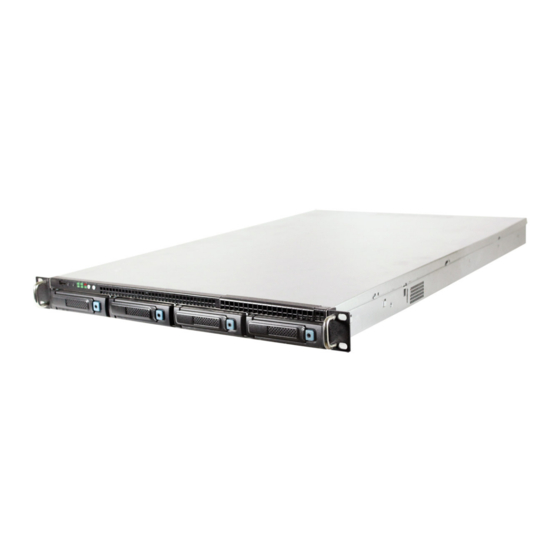
GB109-CT, a 1U 4bay General Purpose Barebone, supports Dual-Core/Quad-Core/6- GB109-CT, a 1U 4bay General Purpose Barebone, supports Dual-Core/Quad-Core/6- Core processors. GB109-CT has 4 x 3.5” size HDD bays w/o expander to maximize I/O Core processors. GB109-CT has 4 x 3.5” size HDD bays w/o expander to maximize I/O bandwidth. -
Page 7: System Specifications
1.2 System Specifications 1.2 System Specifications Dimensions (with chassis ears/protrusions) Dimensions (with chassis ears/protrusions) mm : 482.6 x 711.2 x 44.4 mm : 482.6 x 711.2 x 44.4 W x D x H W x D x H inches : 19 x 28 x 1.75 inches : 19 x 28 x 1.75 Motherboard... - Page 8 • ACPI 1.0/2.0/3.0 • ACPI 1.0/2.0/3.0 • IPMI KCS interface • IPMI KCS interface • PXE 2.0 • PXE 2.0 BIOS Features BIOS Features • SMBIOS 2.0 • SMBIOS 2.0 • WOL • WOL • Serial console redirection •...
-
Page 9: Front View Of Gb109-Ct
1.3 Front View of GB109-CT 1.3 Front View of GB109-CT Hot‐swap HDD Trays Hot‐swap HDD Trays Icon Icon Controls Controls Icon Icon System Behavior System Behavior LED LED Color Color Behavior Behavior Solid: System On Solid: System On ... -
Page 10: Top View Of Gb109-Ct
1.5 Top View of GB109-CT 1.5 Top View of GB109-CT The barebone server includes the basic components shown below. The barebone server includes the basic components shown below. Hot‐swap HDD trays Hot‐swap HDD trays 2.5” Internal 2.5” Internal Drive Bracket Drive Bracket SAS/SATA SAS/SATA Backplane Backplane ... -
Page 11: Chapter 2. Hardware Setup
This section demonstrates maintenance procedures in replacing a defective part once This section demonstrates maintenance procedures in replacing a defective part once the GB109-CT appliance is installed and is operational. the GB109-CT appliance is installed and is operational. 2.1 Chassis Cover 2.1 Chassis Cover... -
Page 12: Central Processing Unit (Cpu)
2.2 Central Processing Unit (CPU) 2.2 Central Processing Unit (CPU) Caution : When unpacking a processor, hold the processor only by its Caution : When unpacking a processor, hold the processor only by its edges to avoid touching the contacts. edges to avoid touching the contacts. - Page 13 4. Align the processor cutouts against the socket notches. 4. Align the processor cutouts against the socket notches. Cutouts Cutouts Caution: The pins of the processor socket are vulnerable and Caution: The pins of the processor socket are vulnerable and easily susceptible to damage if fingers or any foreign objects are easily susceptible to damage if fingers or any foreign objects are pressed against them.
-
Page 14: Installing The Cpu Heatsink
2.2.2 Installing the CPU Heatsink 2.2.2 Installing the CPU Heatsink Note: Apply thermal paste to the bottom of heatsink and spread in Note: Apply thermal paste to the bottom of heatsink and spread in an even thin layer before installing the heatsink. an even thin layer before installing the heatsink. -
Page 15: System Memory
2.3 System Memory 2.3 System Memory This server board supports up to twelve DDR3 800/1066/1333 Registered ECC SDRAM This server board supports up to twelve DDR3 800/1066/1333 Registered ECC SDRAM (recommended) / Unbuffered ECC SDRAM. (recommended) / Unbuffered ECC SDRAM. 1. - Page 16 10 DIMMs 10 DIMMs CPU0 DIMM 0 CPU0 DIMM 0 CPU0 DIMM 0 CPU0 DIMM 0 CPU0 DIMM 0 CPU0 DIMM 0 DIMM 1 DIMM 1 DIMM 1 DIMM 1 CPU1 DIMM 0 CPU1 DIMM 0 CPU1 DIMM 0 CPU1 DIMM 0 CPU1 DIMM 0 CPU1 DIMM 0...
-
Page 17: Drive Bays
2.4 Drive Bays 2.4 Drive Bays 2.4.1 Installing or Replacing 3.5” Hot-swap SAS/SATA HDD 2.4.1 Installing or Replacing 3.5” Hot-swap SAS/SATA HDD 1. Release a drive tray by pressing the unlock button and pinching slightly the 1. Release a drive tray by pressing the unlock button and pinching slightly the lock lever and pulling out the drive tray. -
Page 18: Installing Or Replacing 2.5" Internal Sas/Sata Hdd
2.4.2 Installing or Replacing 2.5” Internal SAS/SATA HDD 2.4.2 Installing or Replacing 2.5” Internal SAS/SATA HDD 1. Release the thumb screw. Pull the bracket holder outward to remove the 1. Release the thumb screw. Pull the bracket holder outward to remove the bracket from the hooks on the chassis. -
Page 19: Riser Card Setting
2.5 Riser Card 2.5 Riser Card 1. 1. RISER CARD PN (PSG CODE) RISER CARD PN (PSG CODE) DESCRIPTION DESCRIPTION PSG-RC-AQ1U-20-111 (PE1U04) PSG-RC-AQ1U-20-111 (PE1U04) 1U Gold finger PCIe X16 to 2 PCIe X8 Riser for 1U Gold finger PCIe X16 to 2 PCIe X8 Riser for Aquarius/Castor Aquarius/Castor RISER CARD DIAGRAM... -
Page 20: Expansion Slot
2.6 Expansion Slot 2.6 Expansion Slot 2.6.1 Install an External Expansion Card to the Riser Card 2.6.1 Install an External Expansion Card to the Riser Card 1. Remove two screws to release the bracket. Then remove the card retainer in 1. -
Page 21: Installing An External Expansion Card To The Riser Card (Low-Profile)
2.6.2 Install an External Expansion Card to the Riser Card (Low-profile) 2.6.2 Install an External Expansion Card to the Riser Card (Low-profile) 1. Remove two screws on top of the bracket holder and twist out the metal 1. Remove two screws on top of the bracket holder and twist out the metal plate to insert expansion card I/O ports. -
Page 22: System Fans
2.7 System Fans 2.7 System Fans Caution: shut down the system before removing the system fans. Caution: shut down the system before removing the system fans. 2.7.1 Removing or Replacing the System Fans 2.7.1 Removing or Replacing the System Fans 1. -
Page 23: Power Supply
2.8 Power Supply 2.8 Power Supply 2.8.1 Removing or Replacing the Power Supply Module 2.8.1 Removing or Replacing the Power Supply Module Hold the PSU lever and firmly pull the PSU out of the server chassis. Hold the PSU lever and firmly pull the PSU out of the server chassis. 2.9 Fan Duct 2.9 Fan Duct 2.9.1 Installing the Fan Duct... -
Page 24: Chapter 3. Motherboard Settings
Chapter 3. Motherboard Settings Motherboard Settings This section describes the jumper settings of AIC’s Castor PSG-M-CTD036D-110 This section describes the jumper settings of AIC’s Castor PSG-M-CTD036D-110 motherboard. We will show the motherboard layout and important jumper settings of the motherboard. We will show the motherboard layout and important jumper settings of the system. -
Page 25: Jumpers
3.2.1 Jumpers 3.2.1 Jumpers DISABLE DISABLE VGA DISABLE VGA DISABLE ENABLE ENABLE DISABLE DISABLE AST ARM AST ARM ENABLE ENABLE RESET RESET AST ARM RESET AST ARM RESET NORMAL NORMAL NORMAL NORMAL CLEAR CMOS CLEAR CMOS CLEAR CLEAR OPEN INVALID OPEN INVALID PCIe Strapping Configuration... -
Page 26: Internal Connectors
3.2.2 Internal Connectors 3.2.2 Internal Connectors 1.Tx 1.Tx BMC DEBUG BMC DEBUG 2.Rx 2.Rx 3.GND 3.GND 9.NC 9.NC 10.GND 10.GND 7.RI# 7.RI# 8.DTR# 8.DTR# UART/COM2 UART/COM2 5.CTS# 5.CTS# 6.TXD 6.TXD 3.RTS# 3.RTS# 4.RXD 4.RXD 1.DSR# 1.DSR# 2.DCD# 2.DCD# 15.GND 15.GND 16.CLK... -
Page 27: Internal Connectors (Continue)
3.2.3Internal Connectors 3.2.3Internal Connectors (continue) (continue) 5.BMC_GPIOE6 5.BMC_GPIOE6 6.BMC_GPIOB2 6.BMC_GPIOB2 BMC GPIO BMC GPIO 4.BMC_GPIOB7 4.BMC_GPIOB7 3.BMC_GPIOE7 3.BMC_GPIOE7 1.GND 1.GND 2.BMC_GPIOH3 2.BMC_GPIOH3 2.3.3V 2.3.3V 1.GND 1.GND 4.GPIOF33 4.GPIOF33 3.GPIOF0 3.GPIOF0 GPIO GPIO 6.GPIOF32 6.GPIOF32 5.GPIOF1 5.GPIOF1 8.GPIOF22 8.GPIOF22 7.GPIOF6 7.GPIOF6 10.GPIOF37... -
Page 28: Internal Leds
3.2.4 Internal LEDs 3.2.4 Internal LEDs LED ON=LAN LINK LED ON=LAN LINK LED BLINK=ACTIVE LED BLINK=ACTIVE 1.GbE1 LED# 1.GbE1 LED# 2.GbE1 LED+ 2.GbE1 LED+ LAN LED LAN LED 3.GbE2 LED# 3.GbE2 LED# 4.GbE2 LED+ 4.GbE2 LED+ 5.GbE3 LED# 5.GbE3 LED# 6.GbE3 LED+ 6.GbE3 LED+... -
Page 29: Chapter 4 : Bios Configuration And Settings
Chapter 4. Chapter 4. BIOS Configuration and Settings BIOS Configuration and Settings Caution: When Quiet Boot IS enabled, OEM LOGO WILL BE displayed Caution: When Quiet Boot IS enabled, OEM LOGO WILL BE displayed INSTEAD OF POST MESSAGES. INSTEAD OF POST MESSAGES. -
Page 30: Bios Setting
3. Identify the BIOS Version 3. Identify the BIOS Version 4. Load Optimal Default setting 4. Load Optimal Default setting 5. Save the setting and exit the BIOS setup utility. 5. Save the setting and exit the BIOS setup utility. ... -
Page 31: Updating Bios
1. AFUDOS is a BIOS update utility with command line interface that works in DOS environment. environment. 2. The latest BIOS version is available from the FAE or AIC website. 2. The latest BIOS version is available from the FAE or AIC website. 3. Enter “flash” at the DOS command line. -
Page 32: Chapter 5 : Bmc Configuration And Settings
Chapter 5. Chapter 5. BMC Configuration and Settings BMC Configuration and Settings Insert BMC IP LAN into the BMC LAN port. There are two methods to setup BMC IP: Insert BMC IP LAN into the BMC LAN port. There are two methods to setup BMC IP: BMC ... - Page 33 Input IP address. Set IP static. Input IP address. Set IP static. Note: type “1” for selecting static IP mode or type “2” for selecting Note: type “1” for selecting static IP mode or type “2” for selecting DHCP mode.
- Page 34 Input subnet mask address. Input subnet mask address. ...
-
Page 35: Method 2 (Use A Dos Tool - Syscheck)
5.2 Method 2 (Use a Dos tool - Syscheck) 5.2 Method 2 (Use a Dos tool - Syscheck) 1. Type : sc –lanset. 1. Type : sc –lanset. 2. Modify IP setting. 2. Modify IP setting. Note: type 1 for selecting static IP mode or type 2 for selecting DHCP Note: type 1 for selecting static IP mode or type 2 for selecting DHCP mode. - Page 36 4. Input submask address. 4. Input submask address. Below IP address is an example using a default IP setting. User is allowed to Below IP address is an example using a default IP setting. User is allowed to change the IP address for realistic use.
-
Page 37: Connect To Bmc
5.3 Connect to BMC 5.3 Connect to BMC Note: This feature works with JAVA 6 runtime installed console Note: This feature works with JAVA 6 runtime installed console environment. environment. Below IP address is an example using default IP setting. User is allowed to change Below IP address is an example using default IP setting. - Page 38 4. Server Health - Sensor Readings: 4. Server Health - Sensor Readings: 5. Configuration 5. Configuration Please refer to AIC BMC User Guide for more information on AIC BMC. Please refer to AIC BMC User Guide for more information on AIC BMC. ...
- Page 39 Mouse Mode setting: Mouse Mode setting: For Windows OS environment, set mode to absolute. For Windows OS environment, set mode to absolute. For Linux OS environment, set mode to relative. For Linux OS environment, set mode to relative. Remote Control: Remote Control: Environmental setting:...
-
Page 40: Updating Bmc Firmware
This is just an example. The latest BMC firmware version is available from the FAE This is just an example. The latest BMC firmware version is available from the FAE or AIC website. or AIC website. After update BMC firmware, please power off and then power on system. -
Page 41: Updating Bmc Configuration
SURE FIRMWARE AND CONFIGURATION VERSIONS ARE CORRECT BEFORE SURE FIRMWARE AND CONFIGURATION VERSIONS ARE CORRECT BEFORE UPDATING. CONSULT THE AIC WEB SITE (http://www.aicipc.com) FOR THE UPDATING. CONSULT THE AIC WEB SITE (http://www.aicipc.com) FOR THE CORRECT COMBINATION OF FIRMWARE AND CONFIGURATION VERSIONS CORRECT COMBINATION OF FIRMWARE AND CONFIGURATION VERSIONS FOR YOUR SYSTEM. -
Page 42: Chapter 6. Technical Support
Chapter 6. Chapter 6. Technical Support Technical Support Http://www.aicipc.com Http://www.aicipc.com TAIWAN TAIWAN Tel: +886.3.313.8386 Tel: +886.3.313.8386 Fax: +886.3.313.8377 Fax: +886.3.313.8377 Email Technical Support: support@aicipc.com Email Technical Support: support@aicipc.com JAPAN JAPAN Tel: +81.43.202.8380 Tel: +81.43.202.8380 Fax: +81.43.202.8381 Fax: +81.43.202.8381 Email Technical Support: support@aicipc.com... - Page 43 Note Note ...
Need help?
Do you have a question about the GB109-CT and is the answer not in the manual?
Questions and answers