Table of Contents
Advertisement
Quick Links
Advertisement
Table of Contents

Related Manuals for AIC CB201-Z1


Summary of Contents for AIC CB201-Z1
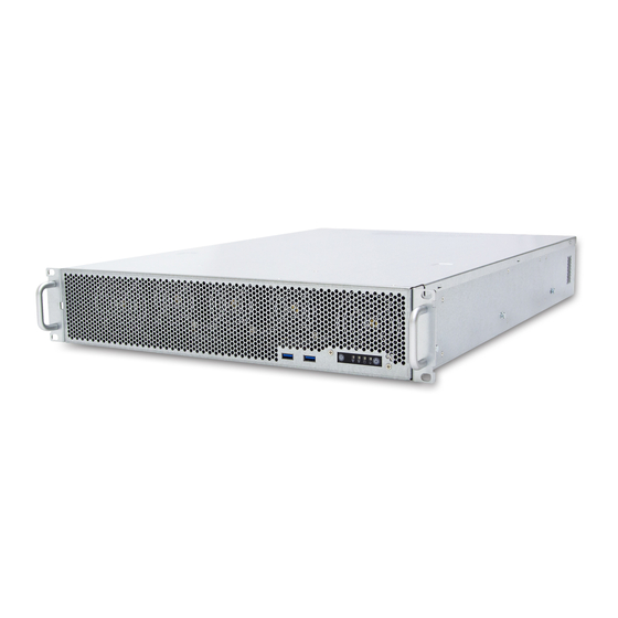
- Page 1 CB201-Z1 Rackmount Storage Chassis User's Manual UM_CB201-Z1_v1.1_011320...
-
Page 2: Table Of Contents
Table of Contents Preface ������������������������������������������������������������������������������������������������� i Safety Instruction �������������������������������������������������������������������������������� ii About This Manual ������������������������������������������������������������������������������ iv Chapter 1� Product Feature ���������������������������������������������������������������� 1 1.1 Components ..................... 1 1.2 Specifications ..................2 1.3 Feature ..................... 3 Chapter 2� Hardware Setup ���������������������������������������������������������������� 5 2.1 Front Door (Optional) ................5 2.2 Top Cover .................... - Page 3 4.5 Platform Configuration ................28 4.5.1 PCH Configuration ................... 29 4.5.2 Miscellaneous Configuration ................. 29 4.5.3 Server ME Configuration ................29 4.5.4 Runtime Error Login ..................30 4.6 Socket Configuration ................31 4.6.1 Processor Configuration ................32 4.6.2 Common RefCode Configuration ..............32 4.6.3 UPI Configuration ....................
- Page 4 Document Release History Release Date Version Update Content September User's Manual release to public. 2019 January Specifications update. 2020...
- Page 5 Copyright © 2019 AIC, Inc� All Rights Reserved� This document contains proprietary information about AIC products and is not to be disclosed or used except in accordance with applicable agreements.
-
Page 6: Preface
Disclaimer AIC shall not be liable for technical or editorial errors or omissions contained herein. The information provided is provided "as is" without warranty of any kind. To the extent permitted by law, neither AIC or its affiliates, subcontractors or suppliers will be liable for incidental, special or consequential damages including downtime cost;... -
Page 7: Safety Instruction
Safety Instruction Before getting started, please read the following important cautions: • All cautions and warnings on the equipment or in the manuals should be noted. • Most electronic components are sensitive to electrical static discharge. Therefore, be sure to ground yourself at all times when installing the internal components. •... - Page 8 • If one of the following situations arise, the equipment should be checked by service personnel: 1. The power cord or plug is damaged. 2. Liquid has penetrated the equipment. 3. The equipment has been exposed to moisture. 4. The equipment does not work well or will not work according to its user manual. 5.
-
Page 9: About This Manual
This document pellucidly presents a brief overview of the product design, device installation, and firmware settings for CB201-Z1. For the latest version of this user's manual, please refer to the AIC website: https://www.aicipc.com/en/productdetail/51200. -
Page 10: Chapter 1� Product Feature
Chapter 1� Product Feature RSC-1DT User Manual Chapter 1. Product Features CB201-Z1 User Manual Chapter 1. Product Feature Before removing the subsystem from the shipping carton, visually inspect the physical condition of the shipping carton. Exterior damage to the shipping carton may indicate that the contents of the carton are damaged. -
Page 11: Specifications
4 x16 PCIe slot (left) 1 x16+ 1 x8 PICe slot • 2 x GbE RJ45 (GPU card support: Please contact AIC Technical Support • 1 x GbE RJ45 dedicated to BMC management for additional information/details.) - 2 x USB3.0 Type A •... - Page 12 CB201-Z1 User Manual Chapter 1. Product Feature 1�3 Feature Front Panel System Switches and LED indicators in front panel Item Description Item Description Power Button LAN2 Activity LED Power Status LED System Reset Button Drive Activity LED 2 x USB 3.0 Type A port...
- Page 13 CB201-Z1 User Manual Chapter 1. Product Feature Top View 2 x 80x38mm fan 3 x 60x38mm fans with Smart Fan control 2 x 80x38mm fan...
-
Page 14: Chapter 2� Hardware Setup
Chapter 2� Hardware Setup CB201-Z1 User Manual Chapter 2. Hardware Setup 2�1 Front Door (Optional) Use a key to unlock the front door. Push the release button on both sides and pull it outward to remove. This information is provided for professional technicians only. -
Page 15: Top Cover
CB201-Z1 User Manual Chapter 2. Hardware Setup 2�2 Top Cover Dislodge the screws on the top cover. Lift the top cover upward. This information is provided for professional technicians only. -
Page 16: Power Supply Unit Module
CB201-Z1 User Manual Chapter 2. Hardware Setup 2�3 Power Supply Unit Module Press the ejector to release the module. Pull the handle to remove the module out of the chassis. Push the new power supply unit into the chassis. Ensure that the module is hooked into the cage. -
Page 17: Fan Module
CB201-Z1 User Manual Chapter 2. Hardware Setup 2�4 Fan Module Initiate the removal of the fan by unplugging the cables and connectors from the fan. Extract the fan by carefully dislodging the rubber connectors on the fan from the securing bracket. - Page 18 CB201-Z1 User Manual Chapter 2. Hardware Setup...
-
Page 19: Hard Disk Drive
CB201-Z1 User Manual Chapter 2. Hardware Setup 2�5 Hard Disk Drive Dislodge the screw on the HDD bracket holder. Pull the bracket holder upward. Slide the HDD out of the bracket holder. This information is provided for professional technicians only. -
Page 20: Riser Card
CB201-Z1 User Manual Chapter 2. Hardware Setup 2�6 Riser Card 2.6.1 Low Profile PCIe Card Pull the riser card bracket holder upward. Insert a new riser card by aligning the gold finger with the slot. 2�6�2 Full Height PCIe Card ... -
Page 21: Slide Rail
CB201-Z1 User Manual Chapter 2. Hardware Setup 2�7 Slide Rail Remove the inner rail. Push the tab forward to release the inner rail. Push Click! Inner rail Outer rail/bracket Install the inner rail onto the chassis. Click! - Page 22 CB201-Z1 User Manual Chapter 2. Hardware Setup Fix the outer rail/bracket assembly to the frame. NOTE Front and rear bracket installation are the same. The left and right side of the rail are symmetrical. Please repeat the installation step for the other side.
-
Page 23: Chapter 3. Hardware Specifications
Chapter 3. Hardware Specifications CB201-Z1 User Manual Chapter 3. Hardware Specification 3�1 Motherboard... -
Page 24: Motherboard Content List
CB201-Z1 User Manual Chapter 3. Hardware Specification 3�2 Motherboard Content List Connector/Jumper/Header Location Connector/Jumper/Header Location SSI power button/ System Panel PWR_SW1 PANEL1 soft off button Connector LAN1 PMBus 1.2 PSU Select LAN port SMART_PSU1 LAN2 Jumper Power Supply SMBus LAN port... - Page 25 CB201-Z1 User Manual Chapter 3. Hardware Specification 3�3 Connector 9 COM1 Connector 19 System Panel Connector (Panel1) RXD1 2 DCD1 HDLED+ 2 POWERLED+ DTR1 4 TXD1 HDLED- 4 N.C. DSR1 6 GND 6 POWERLED- CTS1 8 RTS1# NMIBTN# 8 MLED+...
- Page 26 CB201-Z1 User Manual Chapter 3. Hardware Specification 26 VPP_I2C1 Connector (VPP_I2C1) I2C8SCL 2 I2C8SDA 4 GND I2C12SCL 6 I2C12SDA PLTRST# I2C13SCL 10 I2C13SDA 27 SSI Power Connector (PWR1) 2 +12V 4 +12V 6 +12V 8 +12V 10 +12V 11 12 +12V...
- Page 27 CB201-Z1 User Manual Chapter 3. Hardware Specification 3�4 Jumper 6 VGA Controller Jumper (VGA_SW1) VGA_SW1 Setting Pin1-2 Enable Default Pin2-3 Disable 7 BMC Jumper (BMC_EN1) BMC_EN1 Setting Pin1-2 Enable Default Pin2-3 Disable 8 DMLAN Jumper (DM_IP_SEL) DM_IP_SEL Setting Pin1-2 Normal...
-
Page 28: Led Indicator
CB201-Z1 User Manual Chapter 3. Hardware Specification 3�5 LED Indicator 3�5�1 Internal LED HDDLED1 LOCLED1 MESLED1 SBPWR1 BMCLED1 Standby Power LED SBPWR1 Green On System in standby. Location LED LOCLED1 Identifies location of the server. System temperature warning or a... -
Page 29: Chapter 4. Bios Configuration Settings
Chapter 4. BIOS Configuration Settings CB201-Z1 User Manual Chapter 4. BIOS Configuration To start the BIOS setup utility: 1. Turn on or reboot your system. 2. Press <Del> during POST (<Tab> on remote console) to start the BIOS setup utility. -
Page 30: Bios Menu
CB201-Z1 User Manual Chapter 4. BIOS Configuration 4�2 BIOS Menu Press and to select the options of the menu bar. Press Enter to access the option screen. Menu Description This item displays system information such as CPU bus speed, system... -
Page 31: Main
CB201-Z1 User Manual Chapter 4. BIOS Configuration 4�3 Main Main Feature Option Key Description System time Configures current time. System date Configures current date. -
Page 32: Advanced
CB201-Z1 User Manual Chapter 4. BIOS Configuration 4�4 Advanced Advanced Feature Option Key Description Trusted Computing This item allows to enable and disabble security device. ACPI Settings This item allows you to set the ACPI parameter settings. Smart Settings This item allows you to set the Smart parameters. -
Page 33: Trusted Computing
CB201-Z1 User Manual Chapter 4. BIOS Configuration 4�4�1 Trusted Computing Trusted Computing Security Device Support Enable Disable 4�4�2 APCI Settings ACPI Settings Enable ACPI Auto Enable Disable Configuration Enable Hibernation Enable Disable 4�4�3 Smart Settings Smart Settings Smart Self-Test Enable Disable 4.4.4 Super IO Configuration... -
Page 34: Onboard Lan Configuration
CB201-Z1 User Manual Chapter 4. BIOS Configuration Legacy Console COM1 COM2 Redirection Settings Out-of-Band COM1 COM2 Mgmt Port Serial Port for Out-Of- VT-UTF8 VT100 Terminal Type Band Management/ VT100+ ANSI Windows Emergency 115200 9600 Services (EMS) Console Bits per Second... -
Page 35: Network Stack Configuration
CB201-Z1 User Manual Chapter 4. BIOS Configuration 4.4.9 Network Stack Configuration Network Stack Configuration Ipv4 PXE Enable Disable Support Ipv4 HTTP Enable Disable Support Ipv6 PXE Enable Disable Support Enable Ipv6 HTTP Network Stack Enable Disable Support PXE boot wait... -
Page 36: Iscsi Configuration
CB201-Z1 User Manual Chapter 4. BIOS Configuration 4�4�13 iSCSI Configuration iSCSI Configuration Add an Attempt Delete Attempts Change Attempt Order... -
Page 37: Platform Configuration
CB201-Z1 User Manual Chapter 4. BIOS Configuration 4.5 Platform Configuration Platform Configuration Feature Option Key Description This item displays and provides option to change the PCH PCH Configuration settings. Miscellaneous Configuration This item enables/disables miscellaneous features. Server ME Configuration This item allows you to set server ME configurations. -
Page 38: Pch Configuration
CB201-Z1 User Manual Chapter 4. BIOS Configuration 4.5.1 PCH Configuration PCH Configuration Board Capability SUS_PWR_DN_ACK Deep Disable DeepSx Power Enable in S5 PCH Device Policies Enable in S4 and S5 GP27 Wake From Enable Disable DeepSx PCI-E ASPM Support Per Individual Part... -
Page 39: Runtime Error Login
CB201-Z1 User Manual Chapter 4. BIOS Configuration 4�5�4 Runtime Error Login Runtime Error Login System Errors Enable Disable Whea Settings Whea Support Enable Disable... -
Page 40: Socket Configuration
CB201-Z1 User Manual Chapter 4. BIOS Configuration 4.6 Socket Configuration Socket Configuration Feature Option Key Description Processor Configuration This item sets the Processor related configurations. Common RefCode This item allows you to select options for the Common RefCode Configuration Configuration. -
Page 41: Processor Configuration
CB201-Z1 User Manual Chapter 4. BIOS Configuration 4.6.1 Processor Configuration Processor Configuration Hyper-Threading [ALL] Enable Disable Execute Disable Bit Enable Disable Enable Intel(R) TXT Enable Disable Enable Disable Enable SMX Enable Disable Hardware Prefetcher Enable Disable Adjacent Cache Enable Disable... -
Page 42: Memory Configuration
CB201-Z1 User Manual Chapter 4. BIOS Configuration 4.6.4 Memory Configuration Memory Configuration Enforce POR Auto Disable Memory Frequency Auto 2133 2400 2666 Data Scrambling for Auto Enable Disable DDR4 Memory Topology Read only. Page Policy Auto Closed Adaptive Auto 1-way Interleave 2-way Interleave... -
Page 43: Advanced Management Power Configuration
CB201-Z1 User Manual Chapter 4. BIOS Configuration 4.6.6 Advanced Management Power Configuration Advanced Management Power Configuration Boot performance Set by Intel Max Efficient mode Performance Node Manager CPU P State Control Energy Efficient Turbo Enable Disable Turbo Mode Enable Disable... -
Page 44: Event Logs
CB201-Z1 User Manual Chapter 4. BIOS Configuration 4�7 Event Logs Event Log Feature Option Key Description Allows you to enable and disable all features of Smbios Event Smbios Event Log Logging during boot. View Smbios Event Log Allows you to view Smbios event log information. -
Page 45: Server Management
CB201-Z1 User Manual Chapter 4. BIOS Configuration 4�8 Server Management 4�8�1 Server Management Feature Option Key Description Watchdog Timer Allows you to start up a BIOS timer which can be only be shut off by Intel Management Software after the OS loads. -
Page 46: Bmc Network Configuration
CB201-Z1 User Manual Chapter 4. BIOS Configuration 4.8.4 BMC Network Configuration BMC Network Configuration Config IPV4 Address Previous State Static DynamicBmcDhcp DM_LAN1/Shared LAN source IPV6 IPV6 Support Enable Disable DM_LAN1/Shared LAN 4�8�5 View System Event Log View System Event Log View System Event Log Read only. -
Page 47: Security
CB201-Z1 User Manual Chapter 4. BIOS Configuration 4�9 Security Security Feature Security Set administrator password in the Create New Password window. After Administrator you key in the password, the Confirm New Password window will pop Password out to ask for confirmation. - Page 48 CB201-Z1 User Manual Chapter 4. BIOS Configuration Platform Key (PK) Save to file Set New Erase Key Exchange Key (KEK) Save to file Set New Append Erase Authorized Signature Save to file Set New Append Erase (DBX) Forbidden Signature Save to file...
-
Page 49: Boot
CB201-Z1 User Manual Chapter 4. BIOS Configuration 4�10 Boot Boot Feature Boot Bootup NumLock State Allows you to select the power-on state for the NumLock. Boot Logo Display Allows you to enable and disable the full screen logo display feature. -
Page 50: Tool
CB201-Z1 User Manual Chapter 4. BIOS Configuration 4�11 Tool Tool Feature Tool IPMI HWM Allows you to run the hardware monitor. -
Page 51: Exit
CB201-Z1 User Manual Chapter 4. BIOS Configuration 4�12 Exit Exit Feature Exit Discard Changes & Exit Exit system setup without saving any changes. Save Changes & Reset Exit system setup after saving the changes. Restore Defaults Restore/load default values for all the setup options. -
Page 52: Chapter 5� Technical Support
Chapter 5� Technical Support Taiwain, Global Headquarters South California, United States Address: No� 152, Section 4, Address: 21808 Garcia Lane Linghang N� Rd, Dayuan District, City of Industry, CA 91789, Taoyuan City 337, Taiwan United States Tel: +886-3-433-9188 Toll free: +7-4997019998 Fax: +886-3-287-1818 Tel: +1-909-895-8989 Fax: +1-909-895-8989#157...
Need help?
Do you have a question about the CB201-Z1 and is the answer not in the manual?
Questions and answers