Table of Contents
Advertisement
Quick Links
Advertisement
Table of Contents

Related Manuals for AIC HA202-PH


Summary of Contents for AIC HA202-PH
- Page 1 HA202-PH Storage Server Barebone User's Manual UM_HA202-PH_v3_052518...
-
Page 2: Table Of Contents
CONTENTS PREFACE ������������������������������������������������������������������������������������������� i SAFETY INSTRUCTIONS �������������������������������������������������������������������� ii CHAPTER OVERVIEW ��������������������������������������������������������������������� iv Chapter 1� Product Features ������������������������������������������������������� 1 1�1 Box Content ����������������������������������������������������������������������������������������1 1.2 Specifications �������������������������������������������������������������������������������������2 1�3 Features �����������������������������������������������������������������������������������������������3 Chapter 2� Hardware Setup �������������������������������������������������������� 6 2�1 Central Processing Unit (CPU) �����������������������������������������������������������6 2�2 System Memory ��������������������������������������������������������������������������������14 2�3 Removing and Installing the Chassis Top Cover ���������������������������18 2�4 Removing and Installing the Hard Disk Drive �������������������������������19... - Page 3 Chapter 5. BMC Configuration Settings ����������������������������������� 49 5�1 Method 1 (Use the BIOS Setup) �������������������������������������������������������49 5�2 Method 2 (Use a Dos Tool - Syscheck) ������������������������������������������52 5�3 Connect to BMC �������������������������������������������������������������������������������54 5�4 Updating BMC Firmware ������������������������������������������������������������������58 Chapter 6. Hardware Specification ����������������������������������������� 59 6�1 Backplane ����������������������������������������������������������������������������������������59 6�2 Bridge Board �������������������������������������������������������������������������������������61 6�3 Daughter Board ��������������������������������������������������������������������������������64...
- Page 4 Copyright © 2017 AIC, Inc� All Rights Reserved� This document contains proprietary information about AIC products and is not to be disclosed or used except in accordance with applicable agreements�...
-
Page 5: Preface
• Disclaimer AIC shall not be liable for technical or editorial errors or omissions contained herein. The information provided is provided "as is" without warranty of any kind. To the extent permitted by law, neither AIC or its affiliates, subcontractors or suppliers will be liable for incidental, special or consequential damages including downtime cost;... -
Page 6: Safety Instructions
SAFETY INSTRUCTIONS • Before getting started, please read the following important cautions: • All cautions and warnings on the equipment or in the manuals should be noted. • Most electronic components are sensitive to electrical static discharge. Therefore, be sure to ground yourself at all times when installing the internal components. •... - Page 7 • product, voltage and current marked on the product’s electrical ratings label. The voltage and current rating of the cord should be greater than the voltage and current rating marked on the product. • If the equipment is not used for a long time, disconnect the equipment from mains to avoid being damaged by transient over-voltage.
-
Page 8: Chapter Overview
Chapter 7 Technical Support For more information or suggestion, please verify and contact the nearest AIC corporation representative in your district or visit the AIC website. It is our pleasure to offer the best service for our customers. -
Page 9: Chapter 1� Product Features
• Enclosure( Power supply, fan, HDD tray included) • 2.5’ and 3.5" HDD Tray • Power cord • Screws kit x 1set • Slide rail x 1set ♦ PACKAGE CONTENT MAY VARY PER REGION. HA202-PH User's Manual... -
Page 10: 1.2 Specifications
Chipset with software RAID support SATA (W x D x H) 6x 7pin SATA connectors inches : 17.2 x 33.4 x 3.5 Aspeed AST2400 Advanced PCIe Graphics & Motherboard AIC Server Board Phoenix Remote Management Processor (per node) IPMI Processor product family Support... -
Page 11: 1�3 Features
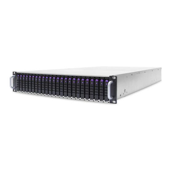
Chapter 1 Product Features 1�3 Features HA202-PH is a reliable 2U storage server barebone with 24 hotswap drives bays for dual port NVMe SSDs. This product is designed to accommodate the AIC-patented serverboard, Phoenix, which supports two Intel® Xeon® Processors E5-2600 v3 and v4 processors and 12 DDR4 DIMM to offer greater perfomance, efficiency, and utility for our customers. - Page 12 Chapter 1 Product Features Front Panel 24 x 2�5” hot swap drive bays Rear Panel AC 1200W 1+1 redundant high-efficiency power supply 80+ 2 x PCIe 3.0 slots (per node) 2 x 10 GbE SFP+ (per node) HA202-PH User's Manual...
- Page 13 Major Components External 2.5” hot swap PCIe SSD x 24 2 x 60 x 56mm fan modules AIC Server Board Phoenix AC 1200W 1+1 redundant high-efficiency power supply 80+ HA202-PH User's Manual...
-
Page 14: Chapter 2� Hardware Setup
Step 2 Proceed to screw 2 and loosen it by giving it two rotations and stop (see letter B). Similarly, loosen screws 3 and 4. Repeat steps A and B by giving each screw two rotations each time until all screws are loosened. Step 3 Lift the heatsink straight up (see letter C). HA202-PH User's Manual... - Page 15 2.1.2.1 Unlatch the CPU Load Plate Step 1 Push the lever handle labeled “OPEN 1st” (see letter A) down and toward the CPU socket. Rotate the lever handle up. Step 2 Repeat the steps for the second lever handle (see letter B). HA202-PH User's Manual...
- Page 16 Step 1 Rotate the right lever handle down until it releases the Load Plate (see letter A). Step 2 While holding down the lever handle, with your other hand, lift open the Load Plate (see letter B). HA202-PH User's Manual...
- Page 17 The processor must align correctly with the socket opening before installation. DO NOT DROP the processor into the socket. NOTE : When possible, a CPU insertion tool should be used when installing the CPU. HA202-PH User's Manual...
- Page 18 Step 2 Repeat the steps to latch the locking lever on the other side (see letter C). Latch the levers in the order as shown. HA202-PH User's Manual...
- Page 19 Step 3 Repeat steps C and D by giving each screw two rotations each time until each screw is lightly tightened up to a maximum of 8 inch-lbs torque (see letter E). CAUTION: Do not over-tighten fasteners. HA202-PH User's Manual...
- Page 20 Remove the processor by carefully lifting it out of the socket, taking care NOT to drop the processor and not touching any pins inside the socket. Install the socket cover if a replacement processor is not going to be installed. HA202-PH User's Manual...
- Page 21 Caution - Possible thermal damage. Avoid moving the heatsink after it has contacted the top of the CPU. Too much movement could disturb the layer of thermal compound, causing voids, and leading to ineffective heat dissipation and component damage. HA202-PH User's Manual...
-
Page 22: 2�2 System Memory
This server board supports up to twelve DDR4 1333/1600/1866/2133 Registered ECC SDRAM(RDIMM) / Load-Reduced DIMM (LRDIMM). JDIMMG0 JDIMMG0 JDIMMA0 JDIMMA0 JDIMMG1 JDIMMG1 JDIMMA1 JDIMMA1 JDIMMH0 JDIMMH0 JDIMMB0 JDIMMB0 JDIMMH1 JDIMMH1 JDIMMB1 JDIMMB1 JDIMMB1 JPWR2 SYS PG LED JUSB_INT JPWR1 JDIMMF0 JDIMMF0 JDIMMC0 JDIMMC0 JDIMME0 JDIMME0 JDIMMC1 JDIMMC1 HA202-PH User's Manual... - Page 23 CPU0 4 DIMMs JDIMM_G0 JDIMM_A0 CPU1 CPU0 JDIMM_H0 JDIMM_B0 JDIMMF1 JDIMMD1 JDIMMF0 JDIMMD0 JDIMMG0 JDIMMA0 JDIMMG1 JDIMMA1 JDIMMH0 JDIMMB0 JDIMMH1 JDIMMB1 CPU1 CPU0 JDIMM_G0 JDIMM_A0 6 DIMMs CPU1 CPU0 JDIMM_H0 JDIMM_B0 JDIMM_F0 JDIMM_D0 JDIMMF1 JDIMMD1 JDIMMF0 JDIMMD0 HA202-PH User's Manual...
- Page 24 JDIMM_D0 JDIMM_E0 JDIMM_C0 JDIMMF0 JDIMMD0 JDIMME0 JDIMMC0 JDIMMG0 JDIMMA0 JDIMMG1 JDIMMA1 JDIMMB0 JDIMMH0 CPU1 CPU0 JDIMMB1 JDIMMH1 JDIMM_G0 JDIMM_A0 JDIMM_G1 JDIMM_A1 12 DIMMs JDIMM_H0 JDIMM_B0 CPU1 CPU0 JDIMM_H1 JDIMM_B1 JDIMM_F0 JDIMM_D0 JDIMM_E0 JDIMM_C0 JDIMMF0 JDIMMD0 JDIMME0 JDIMMC0 HA202-PH User's Manual...
- Page 25 Step 1 Unlock a DIMM socket by pressing the retaining clips outward. Step 2 Insert module vertically and press down until it snaps into place. Note: DIMM notch and socket bump must align as shown. DIMM notch HA202-PH User's Manual...
-
Page 26: 2�3 Removing And Installing The Chassis Top Cover
Step 1 Loosen the screws securing the top covers to the chassis. Step 2 Push the cover away from the opposite cover. Step 3 Lift the cover to remove. 2.3.2 Installing the chassis top cover Secure the top cover on the chassis with the screws. HA202-PH User's Manual... -
Page 27: 2�4 Removing And Installing The Hard Disk Drive
Step 1 Press the release button on the disk drive. Step 2 Pull the disk drive out of the enclosure. 2.4.2 Installing the hard disk drive Push the disk drive into the accurate slot and close the lever. HA202-PH User's Manual... -
Page 28: 2�5 Removing And Installing The Fan Module
NOTE: The heat sink’s fans should be blowing toward the rear end of the chassis. If one of the fans is facing the wrong direction, please remove the heat sink and reinstall it so that it is facing the correct direction. HA202-PH User's Manual... - Page 29 Chapter 2 Hardware Setup 2.5.2 Installing the fan module Make sure that the 4 rubbers and connectors are inserted firmly into the slot. HA202-PH User's Manual...
-
Page 30: 2�6 Removing And Installing The Power Supply Unit Module
2.6.1 Removing the power supply unit module Step 1 Push the latch and hold the tray handle. Step 2 Pull the handle to remove the module out of the enclosure. 2.6.2 Installing the power supply unit module Push the module into the enclosure. HA202-PH User's Manual... -
Page 31: 2�7 Removing And Installing The Hdd Backplane Module
Step 2 Remove the screws x 6 on the module. Step 3 Pull the module out of the enclosure. 2.7.2 Installing the HDD backplane module Step 1 Push the module into the enclosure. Step 2 Secure the screws x 6. HA202-PH User's Manual... -
Page 32: 2�8 Removing And Installing The Solid State Drive (Ssd)
Step 3 Remove the SSD from the bracket kit. Installing the solid state drive 2.8.1 Step 1 Place the SSD into the bracket kit and attach it to the enclosure. Step 2 Secure the screws x 4. HA202-PH User's Manual... -
Page 33: 2�9 Removing And Installing The Battery
Step 2 Remove the braket kit. Step 3 Remove the battery from the bracket kit. 2.9.2 Installing the battery Step 1 Place the battery into the bracket kit and attach it to the enclosures Step 2 Secure the screws x 4. HA202-PH User's Manual... -
Page 34: 2�10 Tool-Less Blade Slide Installation
Step 1 Separate the tool-less slide rail. Pull the inner rail out of the outer rail until it is fully extended. Press the locking tab down to release the inner rail. Outer Rail Middle Rail Inner Rail HA202-PH User's Manual... - Page 35 Step 2 Place the inner rail firmly against the side of the chassis. Make sure that the hooks are straight and aligned with the holes in the inner rail. Screw Screw Step 3 Slide the inner rail forward until it clicks into the locked position. HA202-PH User's Manual...
- Page 36 Chapter 2 Hardware Setup Step 4 Press the locking tab and push the middle rail back into the outer rail. HA202-PH User's Manual...
- Page 37 Chapter 2 Hardware Setup Step 5 Hang the rail hooks on the rack holes and if necessary, secure with screws. Optional Screws HA202-PH User's Manual...
- Page 38 Chapter 2 Hardware Setup Step 6 Repeat step step 5 to mount the four ends, extending the rails as necessary. HA202-PH User's Manual...
- Page 39 Ball Bearing Shuttle Step 8 Align the inner rails with the middle rails and then push evenly on both sides of the chassis until it clicks into the fully extended position. HA202-PH User's Manual...
- Page 40 Step 9 Press the locking tabs on both sides of the chassis simultaneously and push the chassis all the way into the rear of the rack. Screw Screw Step 10 (optional) If additional security is required, secure the chassis handles to the front of the rack with two screws . Complete HA202-PH User's Manual...
-
Page 41: Chapter 3� Motherboard Settings
Placement Rear IO P1 CH2/DIMM0/A0 P0 CH0/DIMM0/A0 P1 CH2/DIMM1/A2 P0 CH0/DIMM1/A2 P1 CH3/DIMM0/A8 P0 CH1/DIMM0/A8 P1 CH3/DIMM1/AA P0 CH1/DIMM1/AA CPU1 CPU0 P1 CH1/DIMM0/A8 P0 CH3/DIMM0/A8 P1 CH0/DIMM0/A0 P0 CH2/DIMM0/A0 P1 Port2 P1 Port3 P0 Port2 P0 Port3 HA202-PH User's Manual... -
Page 42: 3�2 Motherboard Layout
JCMOS JPG_LOCK JPG_LOCK JBMC_I2C10 JBMC_I2C10 JLPC_DP JPMBUS JPMBUS JINTRUDER JBMC_I2C1 RSMRST LED RSMRST LED RSMRST LED JSPI JPWR1 JCOM4 JPCH_GPIO JPCH_GPIO JDIMMF0 JDIMMF0 JDIMMC0 JDIMMC0 Heart Bit LED JDIMME0 JDIMME0 JDIMMC1 JDIMMC1 UID LED JLCM JBMC_GPIO JBMC_DP HA202-PH User's Manual... -
Page 43: 3�3 Motherboard Content List
Chapter 3 Motherboard Settings 3�3 Motherboard Content List HA202-PH User's Manual... -
Page 44: 3�4 Internal Connectors/Jumpers
JPMBUS JINTRUDER JBMC_I2C1 RSMRST LED RSMRST LED RSMRST LED JSPI JPWR1 JCOM4 JPCH_GPIO JPCH_GPIO Heart Bit LED UID LED JLCM JBMC_GPIO JBMC_DP JFRNT(JFRNT_IO) JLPC_DP JBMC_I2C1 JBMC_I2C1 JVGA_INT JVGA_INT JCOM4 JLCM Heart Bit LED UID LED JBMC_GPIO JBMC_DP HA202-PH User's Manual... - Page 45 Chapter 3 Motherboard Settings Internal Connectors/Jumpers JFRNT/JFRNT_IO JVGA_INT JCOM4 JLCM SW_PWR_BTN# +5V_AUX DCDB DSRB SW_RST_BTN# FAN8_TACH DACGOA RXDB RTSB FAN7_TACH DDC_DATAO TXDC TXDB CTSB FAN6_TACH DTRB RXDC FAN5_TACH N�C� KEY (no pin) FAN4_TACH AVSYNCO FAN3_TACH FAN2_TACH FAN1_TACH FAN1_TACH PWM4 PWM4 HA202-PH User's Manual...
- Page 46 Chapter 3 Motherboard Settings Internal Connectors/Jumpers JBMC_DP JBMC_GPIO SCOM2_T3OUT EXTRST# BMC_GPY1 I2C9SDA SCOM2_R4IN BMC_GPY0 I2C9SCL JLPC_DP JBMC_I2C1 CLK_33M_DP80 I2C1SDA PCH_LFRAME_N PCH_GPIO61 RST_PLTRST_N AST_SERIRQ I2C1SCL PCH_LPC_LAD3 PCH_LPC_LAD2 +3�3V PCH_LPC_LAD1 PCH_LPC_LAD0 HA202-PH User's Manual...
- Page 47 Chapter 3 Motherboard Settings Internal Connectors/Jumpers JBUZZER JBUZZER JBMC_RST JSPKR JSPKR JDOM_PWR JDOM_PWR JCMOS JBMC_I2C10 JBMC_I2C10 JINTRUDER JINTRUDER RSMRST LED RSMRST LED RSMRST LED Heart Bit LED JSGPIO JSGPIO UID LED JPMBUS JPMBUS JUSB_INT JUSB_INT JUSB_INT JPCH_GPIO JPCH_GPIO HA202-PH User's Manual...
- Page 48 Chapter 3 Motherboard Settings Internal Connectors/Jumpers JUSB_INT JPCH_GPIO JPMBUS SMB_PMBUS_CLK PCH_GPIO8 SMB_PMBUS_DATA PCH_GPIO21 PMBUS_ALERT_N +3�3V JSGPIO PCH_SCLOCK +3�3V PCH_SDATAOUT1 PCH_SLOAD PCH_SDATAOUT0 JBMC_I2C10 JINTRUDER JDOM_PWR I2C10SCL INTRUDER_N I2C10SDA JSPKR JBUZZER HA202-PH User's Manual...
- Page 49 Chapter 3 Motherboard Settings Internal Connectors/Jumpers JPWR2 SYS PG LED SYS PG LED JCPU_XDP JPG_LOCK JPG_LOCK JPWR1 JPWR2 JPWR1 +12V +12V +12V +12V +12V +12V +12V +12V +12V +5V_AUX POWER OK PS_ON# HA202-PH User's Manual...
-
Page 50: 3�5 System Leds
1G : Orange, 100M: Green 10M/No NIC 3 (Left) Status LED connect: Off Green (Blinking) NIC2 activity detected NIC 4 (Right) NIC2 is not active, LAN cable no connect 1G : Orange, 100M: Green 10M/No NIC 4 (Left) Status LED connect: Off HA202-PH User's Manual... - Page 51 BMC is not active System power good ready SYS PG LED System power good is not ready Resume Well Reset ready RSMRST PG LED Resume Well Reset is not ready UID activity detected UID LED UID not activity detected HA202-PH User's Manual...
- Page 52 JCOMS Short Pin1-2 Normal (Default) Enable Open Disable (Default) Pin2-3C lear CMOS Setting JBMC_RST Short Flash Security override Open Normal (Default) Setting JBMC_RST Short Reset BMC JPG_LOCK Open Normal (Default) Setting JPG_LOCK Short Lock Open Normal (Default) HA202-PH User's Manual...
-
Page 53: Chapter 4. Bios Configuration Settings
INSTEAD OF POST MESSAGES. Step 1 Press ESC to run the setup procedure. Step 2 Click SCU to enter the Setup menu. Caution: For the official released version, the last digit of the BIOS Version must end in an "0." HA202-PH User's Manual... - Page 54 Chapter 4 BIOS Configuration Settings Step 3 Identify the BIOS Version. Step 4 Load Optimal Default setting. Step 5 Save the setting and exit the BIOS setup utility. HA202-PH User's Manual...
-
Page 55: 4�1 Updating Bios
Press <I> key to post system information. Press <F4> key to open POPUP menu. Step 6 Please press <F> key to enter Messiah Flash utility. Step 7 Follow the instruction until the message “Update Flash successfully” is displayed. Step 8 Reboot the system. HA202-PH User's Manual... - Page 56 , H2offt-d.exe and bin file in the same folder. Please follow the instructions to update flash: Step 1 Execute flash.bat to update Flash in the DOS environment. Step 2 Reboot the system. HA202-PH User's Manual...
-
Page 57: Chapter 5. Bmc Configuration Settings
Insert Ethernet LAN cable into the BMC LAN port. There are two methods to setup the BMC IP: BMC management port 5�1 Method 1 (Use the BIOS Setup) Step 1 Click BIOS Setup Advanced H2O IPMI configuration BMC configuration IPv4 source Static HA202-PH User's Manual... - Page 58 Chapter 5 BMC Configuration Settings Step 2 Type in the IP address. Configure the static IP. HA202-PH User's Manual...
- Page 59 Chapter 5 BMC Configuration Settings Step 3 Type in the subnet mask address. HA202-PH User's Manual...
-
Page 60: 5�2 Method 2 (Use A Dos Tool - Syscheck)
5�2 Method 2 (Use a Dos Tool - Syscheck) Step 1 Type in "sc –lanset." Step 2 Modify the IP setting. Note: type 1 for selecting static IP mode or type 2 for selecting DHCP mode. Step 3 Type in the IP address. HA202-PH User's Manual... - Page 61 Below IP address is an example using a default IP setting. User is allowed to change the IP address for realistic use. Step 5 Complete the BMC IP configuration. Note: Type sc.exe –langet command to obtain BMC IP and MAC address. HA202-PH User's Manual...
-
Page 62: 5�3 Connect To Bmc
Password: admin Note: The default user name and password are in lower-case characters. Note: Users who login with the admin user name and password will have full administrative power. The admin password can be changed after login. HA202-PH User's Manual... - Page 63 Chapter 5 BMC Configuration Settings Dashboard: The Dashboard page gives the overall information about the status of a device. Server Health - Sensor Readings: The Sensor Readings page displays all the sensor related information. HA202-PH User's Manual...
- Page 64 Mouse Mode Settings: The KVM Mouse Setting page allows you to configure the mouse mode to relative, absolute, and other. For Windows OS environment, set mode to absolute. For Linux OS environment, set mode to relative HA202-PH User's Manual...
- Page 65 Chapter 5 BMC Configuration Settings Remote Control: The Remote Control page allow you to access any of the managed devices within your system. Environmental Setting: Press “ALT+C” for local and remote OS mouse control switching. HA202-PH User's Manual...
-
Page 66: 5�4 Updating Bmc Firmware
A:>cd SB301C01 A:\ SB301C01>a.bat This is just an example. The latest BMC firmware version is available from the FAE or AIC website. Step 4 After update BMC firmware, please power off and then power on the system. Notes: 1. DO NOT USE EMM386 IN DOS ENVIRONMENT WHEN UPDATING FIRMWARE OR YOU WILL GET A FAIL. -
Page 67: Chapter 6. Hardware Specification
Chapter 6 Hardware Specification Chapter 6. Hardware Specification This chapter provides detailed instruction guide on hardware instruction 6�1 Backplane 6.1.1 Backplane Layout HA202-PH User's Manual... - Page 68 6.1.2 Internal Connectors/Jumpers Power Supply Connector Pin-out (J1) PSU PMBUS (J4) for Bezel (JBezel1) Bezel1_5V Bezel1_3V Power Supply Connector Pin-out (J3) PIC_SDA5_R PIC_SCL5_R Front penal (J2) POWER_SW P_STATUS_LED_GN CANISTER_P_PON P_STATUS_LED_RN CANISTER_S_PON P_STATUS_LED_GN +3VSTBY P_STATUS_LED_RN +3VSTBY MCU JTAG (J4) HA202-PH User's Manual...
-
Page 69: 6�2 Bridge Board
Chapter 6 Hardware Specification 6�2 Bridge Board 6.2.1 Bridge Board layout JVBATT1 JPWR2 JPWR1 JIPMI_LOC1 JVBATT_I2C1 HA202-PH User's Manual... - Page 70 Chapter 6 Hardware Specification 6.2.2 Internal Connectors/Jumpers 12V input from Battery (JVBATT1) 12V & 5VSB. 6A per pin output (JPWR1) PSON 5VSB PSOK IPMI (JIPMI_LOC1) SCL_PW SDA_PW Battery PMBUS (JVBATT_I2C1) PSU_SMBDAT PSU_SMBCLK +12V_BAT_1 +12V_BAT_2 PSU_POK BT_PSNT# HA202-PH User's Manual...
- Page 71 Chapter 6 Hardware Specification (JPWR_SW1) SW_PWR_BTN# MB_SW2 FAN (J11) HW1_TACH_FAN2 HW1_TACH_FAN1 +12V_FAN +12V_FAN PWM1_R FAN (J12) HW2_TACH_FAN2 HW2_TACH_FAN1 +12V_FAN +12V_FAN PWM2_R 12V output (JPWR2) HDD PWR (JHDDPWR1) HA202-PH User's Manual...
-
Page 72: 6�3 Daughter Board
Chapter 6 Hardware Specification 6�3 Daughter Board 6.3.1 Daughter Board layout 6.3.2 Internal Connectors/Jumpers POGO Pin (J1) SW1_P_R SW2_P_R SW3_P_R SW4_P_R SW_BUTTON (SW1) SW1_P SW_BUTTON (SW2) SW2_P SW_BUTTON (SW3) SW3_P SW_BUTTON (SW4) SW4_P HA202-PH User's Manual... -
Page 73: 6�4 Interposer Board
Chapter 6 Hardware Specification 6�4 Interposer Board 6.4.1 Interposer Board layout J201 6�4�2 Internal Connectors/Jumpers GPIO_A GPIO_C GPIO_B VS0_RST# PEX_SCL0_R VS1_RST# PEX_SDA0_R HA202-PH User's Manual... -
Page 74: 6�5 Riser Card
Chapter 6 Hardware Specification 6�5 Riser Card 6.5.1 Riser Card layout JUSB1 JHDD_PWR HA202-PH User's Manual... - Page 75 Chapter 6 Hardware Specification 6.5.2 Internal Connectors/Jumpers PCIe slim x8 slot (CN2)-1 HA202-PH User's Manual...
- Page 76 Chapter 6 Hardware Specification PCIe slim x8 slot (CN2)-2 HA202-PH User's Manual...
- Page 77 Chapter 6 Hardware Specification 100 x 2 Pin Sametc HSEC8 200p slot (CN1)-1 HA202-PH User's Manual...
- Page 78 Chapter 6 Hardware Specification 100 x 2 Pin Sametc HSEC8 200p slot (CN1)-2 HA202-PH User's Manual...
- Page 79 Chapter 6 Hardware Specification External thermal sensor (J1) HDD power supply:12V & 5V (JHDD_PWR) USB 2.0 (JUSB1) External thermal sensor (J2) HA202-PH User's Manual...
-
Page 80: 6�6 Drive Slot Map
Chapter 6 Hardware Specification 6�6 Drive Slot Map HBA CARD MegaRaid CARD HA202-PH User's Manual... -
Page 81: Chapter 7� Technical Support
Chapter 1 Product Introduction Chapter 1 Product Introduction Chapter 7� Technical Support www�aicipc�com • TAIWAN Tel: +886 3 433 9188 Fax: +886 3 287 1818 Email: sales@aicipc�com�tw • CHINA Tel: +86�21�54961421, +86�21�54961422 Fax: Extension: 608 Email Technical Support: support@aicipc�com • AMERICA - West coast Tel: +1�909�895�8989 Fax: +1�909�895�8999 Email: sales@aicipc�com...
Need help?
Do you have a question about the HA202-PH and is the answer not in the manual?
Questions and answers