
Related Manuals for Federal Signal Corporation UltraVoice


Summary of Contents for Federal Signal Corporation UltraVoice
- Page 1 UltraVoice Remote Interface ® Model: UVRI-B Description, Specifications, and Installation Manual 25500444 Rev. A0 0118 Printed in U.S.A. © Copyright 2018 Federal Signal Corporation...
-
Page 2: Limited Warranty
A copy of this limited warranty may also be obtained by written request to Federal Signal Corporation, 2645 Federal Signal Drive, University Park, IL 60484; by email to info@fedsig.com, or by calling +1 708 534-3400. -
Page 3: Table Of Contents
Contents Safety Messages..............................8 General Description ..............................10 Introduction ...............................10 Overview ................................10 Models Description ........................... 11 Features ................................11 Communications Link ............................12 Unit Type ..............................12 RF Frequency ............................13 Security Key ..............................13 128-bit/256-bit Encryption Key ........................13 Unit Address ..............................13 User Programs ..............................14 Status Monitoring ..............................14 Specifications ................................14 Connectors, Configuration Jumpers, Test Points, Controls and Indicators ............ - Page 4 Adjusting the Radio Transceiver (if applicable) ....................43 Control and Status Monitoring ..........................44 Operations................................45 Manual Activation ..............................45 Local Public Address ............................45 Relay Output ..............................46 Sensor Inputs ..............................46 Status Monitoring ..............................46 Quiet Test ................................47 AC/DC Power System ............................47 Applications ................................47 UltraVoice Remote Interface (UVRI-B)
- Page 5 Two-Way Radio Controlled System ........................47 Fire Panel Interface ............................47 Fiber-connected Facility ............................47 Maintenance ................................48 Control Unit Preventive Maintenance .......................48 General Maintenance ............................48 Checking Signal Operational ........................48 Checking the Battery ..........................49 Replacing the Battery ..........................49 Troubleshooting ..............................49 Replacement Parts ..............................50 Getting Service ..............................50 Appendix A UVRI-B Field Service Data Sheet .....................51 Description, Specifications, and Installation Manual...
- Page 6 Table 22 Environmental and Physical .........................25 Table 23 Software Tests ............................25 Table 24 Concrete or Filled Cement Block Wall Mounting Materials ..............31 Table 25 Hollow Block Wall Mounting Materials ....................32 Table 26 Wood Stud Wall Mounting Materials ....................32 UltraVoice Remote Interface (UVRI-B)
- Page 7 Table 27 Metal Stud Wall Mounting Materials .....................32 Table 28 Installer Supplied UVRI-B Electrical Installation Material List ............33 Table 29 Manual Activation Buttons on Control Board ..................45 Table 30 Sensor Connections ..........................46 Table 31 Troubleshooting .............................49 Table 32 Replacement Part Numbers ........................50 Figures Figure 1 UVRI-B Parts Layout ..........................10 Figure 2 UVRI-B Boards (Lines A, B, C for Control Board to Amplifier Connection) ........
-
Page 8: Safety Messages
Activating the sirens may not result in people taking the desired actions if those to be warned are not properly trained about the meaning of siren sounds. Siren users should follow FEMA recommendations and instruct those to be warned of correct actions to be taken. UltraVoice Remote Interface (UVRI-B) - Page 9 Safety Messages • After installation, service, or maintenance, test the siren system to confirm that it is operating properly. Test the system regularly to confirm that it will be operational in an emergency. • If future service and operating personnel do not have these instructions to refer to, the siren system may not provide the intended audible warning and service personnel may be exposed to death, permanent hearing loss, or other bodily injury.
-
Page 10: General Description
General Description General Description Introduction The UltraVoice Remote Interface unit (UVRI-B) provides remote extension of Federal Signal indoor and outdoor warning systems. The UVRI-B is available with a number of standard and optional features to allow efficient and cost-effective alerting and notification. -
Page 11: Models Description
General Description Operation is supervised and status information is transferred back to the control station(s) through one or more available communications networks. The UVRI-B monitors the audio output level and the Remote Activation input to verify proper operation. Remote Fire Alarm and PA systems provide a contact closure to indicate proper operation. The control board is powered from 120 or 240 Vac with 12 Vdc battery backup. -
Page 12: Communications Link
3. Security Key 4. 128/256-bit Encryption Key 5. Unit Address 6. Configuration Jumper Settings Unit Type The Federal Signal Commander System requires configuration based on the communications method. See the Commander Software Manual for configuration information. UltraVoice Remote Interface (UVRI-B) -
Page 13: Rf Frequency
General Description RF Frequency Program the radio transceiver with the RF frequency(s), channel spacing and power output before placing into service. These settings are pre-set at the factory if the requirements are provided with the order. Security Key The Security Key is a unique number assigned to the system that prevents interference of nearby systems operating on the same RF frequency. -
Page 14: User Programs
100 W Amplifier Output with addition of output transformer 28.3 V into 8 Ω load for 100 W Frequency response +/- 3 dB from 300-6.0 kHz at transformer output < 5% at transformer output Hum and Noise < -45 dB UltraVoice Remote Interface (UVRI-B) -
Page 15: Table 4 Serial And I
Specifications Table 4 Serial and I C Ports on Control Board Serial Port Protocol RS232C 115200,N,8,1 C Port Protocol Philips Standard I Table 5 Relay Outputs on Control Board Quantity Contact Rating 10 A, 250 Vac, 30 Vdc, Optically isolated, (NO and NC) Table 6 600 ohm I/O Balanced Line on Control Board Audio Input Level Minimum of 0.10 to at least 2 V... -
Page 16: Table 11 Tc1 Sensing Inputs On Control Board
Space between Stacked codes minimum 1.25 seconds AFSK Baud rate 1200 bps Modem type MSK (minimal shift key) Mark frequency 1200 Hz Space frequency 1800 Hz Error checking 16 bit CRC Supports standard EAS codes and wildcards UltraVoice Remote Interface (UVRI-B) -
Page 17: Connectors, Configuration Jumpers, Test Points, Controls And Indicators
Specifications POCSAG Supports Binary frequency shift keying 512 Baud numeric messages Decode Sensitivity 18 dB SINAD for tone (except with CTCSS tones > 200 Hz and decode tones < 400 Hz) and 21 dB SINAD for MSK, EAS, POCSAG and DTMF with 50 ms/50 ms or greater timing Two Way Formats Federal Packet Digital and DTMF... - Page 18 600 ohm PTT (Typically short to activate PA) Spare # 2 Common JP25 Isolated Supply Output (VISO) Isolated +5V Isolated (-) JP31 Serial Port #2 JP32 Serial Port #1, Programming/FLASH JP33 Rotation Relay Output Common Normally Open Normally Closed UltraVoice Remote Interface (UVRI-B)
- Page 19 Specifications JP34 Relay Outputs Relay # 1 Common Relay # 1 Normally Open Relay # 1 Normally Closed Relay # 2 Common Relay # 2 Normally Open Relay # 2 Normally Closed Relay # 3 Common Relay # 3 Normally Open Relay # 3 Normally Closed Relay # 4 Common Relay # 4 Normally Open...
-
Page 20: Figure 2 Uvri-B Boards (Lines A, B, C For Control Board To Amplifier Connection)
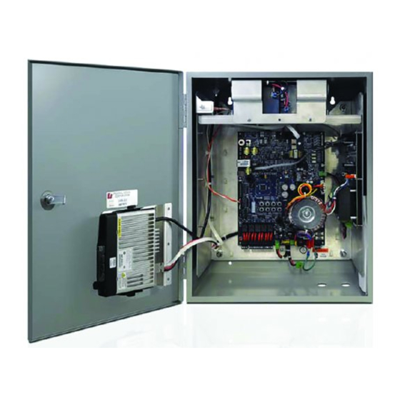
Sensor Inputs (JP24) (S2-S9) Isolated Supply Reset (JP25) Serial Port #1 Site Address (JP32) Switch (S1) Radio Battery Switch 5 A Fuses Power (JP36) (S10) (JP35) 20 Amp JP33 JP34 AC Power (JP38) Rotation Relay Relay Outputs UltraVoice Remote Interface (UVRI-B) -
Page 21: Figure 3 Control Board With Configuration Jumpers, Controls, And Indicators
Specifications Figure 3 Control Board with Configuration Jumpers, Controls, and indicators JP39 D9 D10 JP14 JP13 JP2 JP3 JP11 JP12 JP10 JP16 JP18 JP17 JP15 R103 R141 JP20 JP41 JP19 JP31 D40, D41, D42 JP7 JP42 JP21 JP40 JP43 JP23 JP22 JP44 JP24... -
Page 22: Configuration Jumpers
10 V/25 V Output Configuration Jumper Pins: 25 V Output 10 V Output JP15 Voice Output Configuration Jumper Pins: Normal Equalization Treble Boost JP16 Fast DTMF Decode. Short for fast timing. JP17 Disable Digital Receive. Short to disable. UltraVoice Remote Interface (UVRI-B) -
Page 23: Table 16 Configuration Jumpers On The Amplifier Board
Specifications JP20 Siren Audio Channel Select Jumper: Signal 0, A Signal 1, B JP27 Options Connector: Microcontroller Input Ground JP40 Options Jumper - future use JP44 Short to enable Sounder/Piezo Table 16 Configuration Jumpers on the Amplifier board Audio Input Level Select 1 and 2 –... -
Page 24: Indicators
Relay #2 Output Active ISO 12V D105 Relay #3 Output Active D107 Relay #4 Output Active D118 Battery Charging Table 19 Indicators on the Amplifier board Output Current Indicator Output Voltage Indicator Amp Fault Speaker Line Fault Power UltraVoice Remote Interface (UVRI-B) -
Page 25: Pot Settings
Specifications POT Settings Table 20 POT Settings on the Control board Output level for 10 V/25 V and 8 Ω, 0.7 W Audio outputs, (Default = Turn clockwise 20 turns or all of the way up.) R103 Digital Voice Gain, (Default = Turn clockwise 20 turns or all of the way up.) Table 21 POT Settings on the Amplifier board Volume Control,... -
Page 26: Configuring
The UVRI-B requires a 120 Vac or 240 Vac 50 to 60 Hz power source to power the UVRI-B and charge the internal 12 V battery. You can configure the UVRI-B to be powered from 24 Vdc. UltraVoice Remote Interface (UVRI-B) -
Page 27: Figure 4 Typical Uvri-B Installation Drawing (Fire Panel Interface)
Installation You can use several methods to activate the UVRI-B. Use the manual activation buttons and a hand-held microphone to activate the UVRI-B locally. Use landline control through normally open contact switches. Make connections directly to the controller terminal block. Activate the UVRI-B remotely through the optional radio receiver or an external 600 ohm audio source. -
Page 28: Figure 5 Uvri-B Cabinet Dimensional - Front And Side View
Installation Figure 5 UVRI-B Cabinet Dimensional - Front and Side View 1.50 1.82 6.62 20.00 20.36 16.30 6X 1/2" CONDUIT KNOCKOUTS 3.34 2.50 1.74 16.00 UltraVoice Remote Interface (UVRI-B) -
Page 29: Figure 6 Uvri-B Cabinet Dimensional - Back View
Installation Figure 6 UVRI-B Cabinet Dimensional - Back View 2X R.16 2X R.25 17.88 2X .31 11.00 Description, Specifications, and Installation Manual... -
Page 30: Figure 7 Uvri-B Drawing Of System
Installation Figure 7 UVRI-B Drawing of system UltraVoice Remote Interface (UVRI-B) -
Page 31: General Mounting Guidelines
Installation General Mounting Guidelines Use good installation methods and follow local ordinances for mounting cabinet. These general installation instructions are pertinent to all installations. Specific mounting methods and required installation materials are described in the next section. 1. There are two keyhole type slots and two pre-drilled holes for mounting, located on the back panel of the cabinet. -
Page 32: Hollow Block Wall Mounting Guidelines
Material Description Purpose 1/4 in x 2 in lag bolts Cabinet mounting bolts 2 ft x 2 ft B/C or better plywood Mounting backboard #14 x 2 in metal stud screws Backboard mounting Construction adhesive Backboard mounting UltraVoice Remote Interface (UVRI-B) -
Page 33: Table 28 Installer Supplied Uvri-B Electrical Installation Material List
Installation 1. Locate the wall studs for attaching the Mounting Backboard to the wall. 2. Mark the wall stud location on the mounting backboard and drill pilot holes for the #14 metal stud screws. Place three screws in each stud evenly spaced apart. 3. -
Page 34: Electrical Connections
UVRI-B cabinet and to pin 1 of JP38, GND, on the UVRI-B control board. 7. To avoid shorting the output of the charger, do not apply AC power to the UVRI-B controller before making the battery connections described later in this section. UltraVoice Remote Interface (UVRI-B) -
Page 35: Wiring Guidelines For 240 Vac Electrical Service
Installation Wiring Guidelines for 240 Vac Electrical Service Review the following wiring guidelines: 1. Install a dedicated 15 A breaker in an existing breaker panel or install a new breaker panel if necessary for the UVRI-B. 2. Install conduit from the beaker panel to a conduit entrance in the bottom of the UVRI-B. -
Page 36: Speaker Connections (Jp2 On The Amplifier Board)
External 20 to 28 Vdc can be connected to JP23 with the (+) connected to pin #1 and the (-) to pin #4. The unit may draw up to 7 Amps at full power. Contact Federal Signal for information regarding 24 Vdc use. UltraVoice Remote Interface (UVRI-B) -
Page 37: 600 Ohm I/O Connections (Jp8 On The Uvri-B Control Board)
Installing the Antenna 600 Ohm I/O Connections (JP8 on the UVRI-B Control board) Control Connections Use terminal block JP8 on the UVRI-B control board for making connections to 600 ohm balanced audio equipment such as a direct connection to an SS2000+ or other type of control and status monitoring equipment. -
Page 38: Installing The Antenna
2. Find the proper element dimension chart for your antenna, within the antenna instructions, and trim each element according to your operating frequency. Use care to trim equal lengths from each end of each element ensuring that the mounting hole is at the center. UltraVoice Remote Interface (UVRI-B) - Page 39 Installing the Antenna NOTE A: Proper trimming and adjustment is critical to the Voltage Standing Wave Ratio, known as VSWR. (High reflected power levels decrease forward power. The life of the radio and transmit capabilities are dependent upon the VSWR being low as possible).
- Page 40 DMM not having the ability to check the cable at high frequencies). If that does not take care of the problem, replace the antenna. UltraVoice Remote Interface (UVRI-B)
-
Page 41: Installing The Omni Fiberglass Antenna Models
Installing the Antenna Installing the Omni Fiberglass Antenna Models NOTE: No tuning is required for this model. “Figure 9 Omni Antenna Installation Example” on page 42. To install the Omni antenna, do the following: 1. Install antenna, (using installation bracket or equivalent) as high as possible, such that the antenna cable and obstacles allows, and install on side of pole closest to the receiving station. -
Page 42: Figure 9 Omni Antenna Installation Example
Installing the Antenna Figure 9 Omni Antenna Installation Example Figure 10 Antenna Grounding UltraVoice Remote Interface (UVRI-B) -
Page 43: Pre-Operational System Configuration And Testing
Pre-operational System Configuration and Testing Pre-operational System Configuration and Testing The following procedures should be performed by a properly trained technician to ensure the equipment is operating properly. Visual Inspection To conduct a visual inspection: 1. Fill out the Field Test Data Sheet to document the following inspections and tests. See Appendix A. -
Page 44: Control And Status Monitoring
2. Test the control and status monitoring features from each control point. Test each control function and all status indications using Commander. Verify each status point provides the proper indication of both pass and fail conditions. UltraVoice Remote Interface (UVRI-B) -
Page 45: Operations
Operations Operations Manual Activation If configured, use the manual activation switches to activate siren functions. Buttons are located on the Control Board. Figure 11 UVRI-B Activation Buttons Table 29 Manual Activation Buttons on Control Board Function Switch Function Code # 1 Activation Switch Code # 5 Activation Switch Code # 6 Activation Switch Code # 2 Activation Switch... -
Page 46: Relay Output
The UVRI-B monitors power, battery, door opening, amplifier status and other important system components. The UVRI-B includes an external fault indicator when any of the following occur: battery voltage, charger fault, AC power, intrusion, amplifier/line faults, UltraVoice Remote Interface (UVRI-B) -
Page 47: Quiet Test
Applications audio A and B. Quiet Test The Federal Signal Commander System can manually or automatically activate Quiet Test for verification of system operation. Quiet Test uses a 20 kHz tone to test tone generators and optional amplifiers. To configure the quiet test, see the Federal Signal Commander Manual. -
Page 48: Maintenance
5. Verify that the system status is reported correctly at the control point. Check each status point to verify both pass and fail conditions are correctly reported. Verify that the relay output closes with each function activated. UltraVoice Remote Interface (UVRI-B) -
Page 49: Checking The Battery
Troubleshooting Checking the Battery To check the battery: 1. Remove AC power and measure the DC voltage across the DC input connector on the control board. If the battery has been charging for at least 24 hours, this voltage should be above 12.75 Vdc. 2. -
Page 50: Replacement Parts
If you are experiencing any difficulties, contact Federal Signal Customer Care at: 800-548-7229 or 708-534-3400 extension 5822 or Technical Support at: 800-524-3021 or 708-534-3400 extension 7329 or through e-mail at: techsupport@fedsig.com. For instruction manuals and information on related products, visit: http://www.fedsig.com/ UltraVoice Remote Interface (UVRI-B) -
Page 51: Appendix A Uvri-B Field Service Data Sheet
Appendix A UVRI-B Field Service Data Sheet Appendix A UVRI-B Field Service Data Sheet Customer: Project Number: Date: Contact Person: Phone Second Phone Radio Shop: Contact: Phone: Siren Type: S/N: Voltage: Controller Type: Antenna: Omni A/C Service: O.H Yagi U.G. Cabinet Mounted External Mounted CPU Software... - Page 52 2645 Federal Signal Drive University Park, Illinois 60484-3617 www.fedsig.com Customer Support 800-548-7229 • +1 708 534-3400 Technical Support 800-524-3021 • +1 708 534-3400...
Need help?
Do you have a question about the UltraVoice and is the answer not in the manual?
Questions and answers