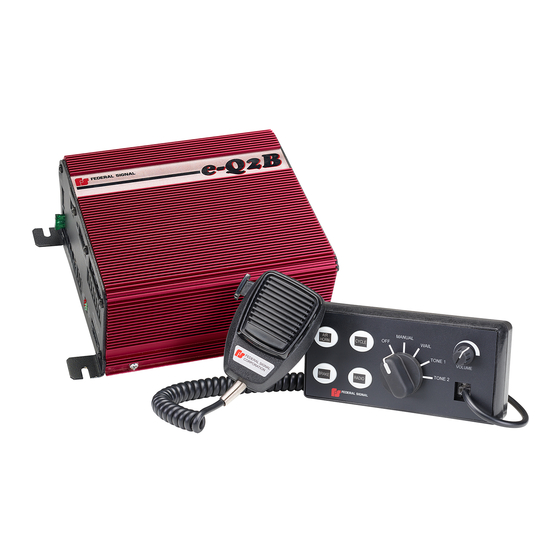
Federal Signal Corporation e-Q2B Installation Maintenance And Service Manual
Electronic siren system
Hide thumbs
Also See for e-Q2B:
- Installation maintenance and service manual (60 pages) ,
- Instruction sheet (8 pages)

Related Manuals for Federal Signal Corporation e-Q2B


Summary of Contents for Federal Signal Corporation e-Q2B
- Page 1 Electronic Siren System Installation, Maintenance, and Service Manual 255394 REV. E0 1120 Printed in U.S.A. © Copyright 2011-2020 Federal Signal Corporation...
- Page 2 A copy of this limited warranty can also be obtained by written request to Federal Signal Corporation, 2645 Federal Signal Drive, University Park, IL 60484, email to info@fedsig.com or call +1 708-534-3400.
-
Page 3: Table Of Contents
Wiring the Siren Amplifier ........................18 Connecting to the Serial Ports ......................18 Connecting the Foot Switches for Cycle, Brake, and Air Horn ..........19 Connecting the Switch Input for the Model e-Q2B-200-RCFD ..........20 Connecting Speakers to the e-Q2B ....................21 Connecting the e-Q2B to the Rumbler 2 Low Frequency Amplifier ........ - Page 4 Distributing the Safety Message Card ....................43 Applying the Siren Safety Labels in the Vehicle ................43 Operating the Standard e-Q2B Siren System .................44 Siren Tones ..............................44 Siren Priorities ............................44 Manual Mode ............................45 Cycle Foot Switch/Push Button .....................45 Brake Foot Switch/Button ........................45...
- Page 5 Table 2 Siren specifications: 200 watts ......................13 Table 3 Siren Specifications: 100 watts ....................... 13 Table 4 Kit contents: Models e-Q2B-100 and e-Q2B-200 (standard control head) ......... 14 Table 5 Kit contents: Models e-Q2B-100 and e-Q2B-200 (flush-mount control head) ......14 Table 6 Kit contents: Model e-Q2B-200-RCFD ....................
- Page 6 Figure 40 PA volume knob replacement .......................54 Figure 41 Control head removed from mounting surface .................55 Figure 42 Fuse replacement in the siren amplifier ..................57 Figure 43 Mounting Template for Flush-Mount Control Head ..............59 e-Q2B Electronic Siren System Federal Signal www.fedsig.com...
-
Page 7: Safety Messages For Installers And Operators
Safety Messages for Installers and Operators For your safety, read and understand this manual thoroughly before installing, operating, and servicing the e-Q2B Siren Amplifier. The safety messages presented in this section and throughout the manual are reminders to exercise extreme care at all times. - Page 8 • Locate the control head so the vehicle, controls, and microphone can be operated safely. • When drilling into a vehicle structure, enure that both sides of the surface are clear of anything that could be damaged. e-Q2B Electronic Siren System Federal Signal www.fedsig.com...
-
Page 9: Safety Messages To Operators Of Federal Signal Sound/Light Systems
After Installation • After installation, test the emergency warning system to ensure that it is operating properly. • Test all vehicle functions, including horn operation, vehicle safety functions, and vehicle light systems, to ensure proper operation. Ensure that installation has not affected vehicle operation or changed any vehicle safety function or circuit. - Page 10 • Do not use a magnet mounting system on vehicles with vinyl tops. • To prevent sliding of light assembly on mounting surface, avoid quick acceleration and hard stops. Failure to follow these precautions may result in property damage, serious injury, or death. e-Q2B Electronic Siren System Federal Signal www.fedsig.com...
-
Page 11: An Overview Of The E-Q2B Siren System
Q sound. To deliver the Q sound effectively, the e-Q2B produces a full 200 watts of output. The e-Q2B produces wail, yelp, priority, and manual siren with brake tones, as well as an air horn sound. -
Page 12: Convergence Network Control Head
An Overview of the e-Q2B Siren System Convergence Network Control Head The Convergence Network control head digitally transmits and prioritizes end-user commands. The control head/amplifier interface uses solid-state digital decoding, which minimizes interconnection complexity. The control head allows the user to operate several siren functions. -
Page 13: Table 2 Siren Specifications: 200 Watts
An Overview of the e-Q2B Siren System Table 2 Siren specifications: 200 watts Operating Current 20 A (nominal) (13.6 V battery, 5.5-ohm load at high power) Frequency Range 725 to 1600 Hz Nominal Cycle Rate Wail: 12 cycles per minute... -
Page 14: E-Q2B Kit Contents
Ensure all parts in the packing list are included in the shipment. If any parts are missing, call Federal Signal Customer Support at 1-800-264-3578, 7 a.m. to 5 p.m., Monday through Friday, CT. Table 4 Kit contents: Models e-Q2B-100 and e-Q2B-200 (standard control head) Qty. Description... -
Page 15: Table 6 Kit Contents: Model E-Q2B-200-Rcfd
An Overview of the e-Q2B Siren System Table 6 Kit contents: Model e-Q2B-200-RCFD Qty. Description Part Number Connector, 4-Position, Speaker 140417-04 Connector, 3-Position, Power 140535 Connector, 12-Position 140584-12 Card, Safety Instructions 256B691 Label, Warning, Siren/Speaker 1612339 Installation, Maintenance, and Service Manual... -
Page 16: Wiring The E-Q2B Siren System
Do not install it in areas where the air flow is restricted. Do not mount the unit near a heater duct or under the hood. UNIT IS NOT WATERPROOF: The housing of the e-Q2B siren amplifier is NOT waterproof. The module must be mounted in a location that is sheltered from falling rain, snow, standing water, etc. -
Page 17: Figure 1 Dimensions Of The Control Head
Wiring the e-Q2B Siren System Wiring connectors are located on the siren amplifier. Ground, ignition, and power connections are located on the three-position, pluggable, terminal block. To maintain the reliability of the siren amplifier, do not block the air vents or the fan. -
Page 18: Wiring The Siren Amplifier
To prepare the vehicle for the electrical installation of the e-Q2B Siren System: 1. After planning where to route the wires and cables for the e-Q2B Siren System components, such as Federal Signal warning lights, directional lights, and speakers, drill the holes for the wiring. -
Page 19: Connecting The Foot Switches For Cycle, Brake, And Air Horn
Wiring the e-Q2B Siren System Figure 3 shows the network connections on the siren amplifier. Refer to the mounting instructions included with the products after you connect all system devices. Figure 3 Serial port locations FEDERAL SIGNAL PARK BRAKE GRND... -
Page 20: Connecting The Switch Input For The Model E-Q2B-200-Rcfd
PA/radio rebroadcast function overrides the AIR HORN function. Connecting the Switch Input for the Model e-Q2B-200-RCFD The Model e-Q2B-200-RCFD siren is designed to operate without a control head. The siren produces a continuous e-Q wail tone while the CYCLE input is activated. -
Page 21: Connecting Speakers To The E-Q2B
11 ohms. The Model e-Q2B-100 operates one 100-watt speaker with an impedance of 11 ohms. The e-Q2B-200 siren amplifier is designed to operate optimally with a Federal Signal BP200-Q or BP200-EF 200-watt speaker system, which is not included as part of the electronic siren. - Page 22 Connecting the BP200 Speaker to the e-Q2B-200 To connect the 200-watt speaker system to the Model e-Q2B-200 siren amplifier: 1. Mount the e-Q2B Siren System components according to the instructions included with each product.
-
Page 23: Figure 6 E-Q2B 200-Watt Speaker Connections (Bp200-Q Or Bp200-Ef)
THAT IS 18 AWG OR THICKER 290A6805 Connecting Two BP100 or ES100 Speakers to the e-Q2B-200 To connect the two 11-ohm, 100-watt speakers to the Model e-Q2B-200 siren amplifier: 1. Mount the e-Q2B Siren System components according to the instructions included with each product. -
Page 24: Figure 7 E-Q2B 200-Watt Speaker Connections With Two 100-Watt Speakers
11 OHM, 100 WATT EACH 290A6806 Connecting One BP100 Speaker to the e-Q2B-100 To connect one 11-ohm, 100-watt speaker to the Model e-Q2B-100 siren amplifier: 1. Mount the e-Q2B Siren System components according to the instructions included with each product. -
Page 25: Figure 8 Bp100 100-Watt Speaker Connections
Wiring the e-Q2B Siren System Figure 8 BP100 100-watt speaker connections MODEL eQ2B-100 1. LOOSEN SCREW. SPEAKER OUTPUT 2. INSERT STRIPPED WIRE IN CONNECTOR. 3. TIGHTEN SCREW. LIMIT- -POWER SHORT- -OUTPUT THERMAL- -LOAD CONNECT TO A OR B ONE BP100 SPEAKER,... -
Page 26: Figure 9 Rumbler 2 Connections To The E-Q2B
Wiring the e-Q2B Siren System Figure 9 Rumbler 2 connections to the e-Q2B GREEN WHITE BLACK e-Q2B Electronic Siren System Federal Signal www.fedsig.com... -
Page 27: Connecting The E-Q2B To The Rumbler
2 Low Frequency Amplifier ® The e-Q2B has a Rumbler audio output that enables it to interface to a Federal Signal Rumbler 2 siren amplifier. The Rumbler 2 intersection-clearing system uses the output of the e-Q2B siren amplifier to synthesize a low frequency signal. It then amplifies the signal to drive a Federal Signal low-frequency siren speaker. -
Page 28: Figure 10 Connections For Horn-Ring Transfer
Wiring the e-Q2B Siren System Figure 10 Connections for horn-ring transfer PARK BRAKE GRND CYCLE REMOTE MIC RADIO RING HORN RMBLR RMBLR RADIO RADIO ENBL RADIO 12-POSITION 1. INSERT SCREWDRIVER TENSION CLAMP TO OPEN TENSION CLAMP. CONNECTOR 2. SLIP WIRE INTO CONNECTOR. -
Page 29: Enabling Radio Rebroadcast Over The Siren Speakers
Wiring the e-Q2B Siren System Enabling Radio Rebroadcast Over the Siren Speakers To enable incoming two-way radio messages to be amplified by the siren amplifier and rebroadcast over the siren speakers: NOTE: The 12-position tension clamp connector accepts 18 AWG to 22 AWG wire. -
Page 30: Connecting The Park Detection Circuit
Wiring the e-Q2B Siren System Connecting the PARK Detection Circuit The PARK detection circuit sends a signal to the siren amplifier to mute all siren functions when the vehicle transmission is shifted into park or neutral. The circuit can detect a +12 V signal or a –BAT signal. -
Page 31: Connecting The Control Head
2. Plug the other end of the cable into the connector on the back of the control head. 3. To provide strain relief, secure the cables with installer-supplied clamps and hold- downs. Figure 13 Convergence Network connection between e-Q2B and control head FEDERAL SIGNAL CONTROL HEAD MUST... -
Page 32: Figure 14 Microphone Connections
Wiring the e-Q2B Siren System flexibility in selecting mounting locations for the microphone. For instructions on adjusting the PA volume, which is available only when the microphone is connected to the control head, see “Setting the Gain for Public Address (PA)” on page 36. -
Page 33: Connecting The E-Q2B System To The Battery
1. Connect the 10 AWG red positive lead (+) to a positive power source capable of supplying 40 amperes. Install a user-supplied 30-ampere fuse (minimum) at the source. The e-Q2B is internally fused at 30 amperes. See Figure 15 on page 34. Installation, Maintenance, and Service Manual... -
Page 34: Figure 15 Connections For Power, Ground, And Ignition
Wiring the e-Q2B Siren System 2. Connect the 10 AWG negative (–) black lead directly to the negative battery terminal. 3. Connect the 12 AWG white lead with the red stripe to a switched circuit that is hot, or active, in the ON and START position of the vehicle ignition system. Install a user-supplied 2-ampere fuse at the source. -
Page 35: Setting The Gain For Radio Rebroadcast And Pa
System. The Radio Rebroadcast function is available only when the siren is in MANUAL Mode. The gain control for radio rebroadcast is a potentiometer with a screw head on the front of the siren amplifier. -
Page 36: Setting The Gain For Public Address (Pa)
CONTROL HEAD MIC JACK, NOT SIREN MIC JACK NOTE: Audio feedback depends upon the microphone gain, open windows, speaker placement, and the proximity of reflecting surfaces such as walls, buildings, or other vehicles. e-Q2B Electronic Siren System Federal Signal www.fedsig.com... -
Page 37: Mounting The Siren Amplifier And Control Head
Mounting the Siren Amplifier and Control Head Mounting the Siren Amplifier and Control Head The next step in the installation after wiring and connecting the e-Q2B Siren System is to permanently mount the siren amplifier and control head in the vehicle. Verify that the mounting locations you selected earlier are safe for installing these components. -
Page 38: Mounting The Siren Amplifier
VEHICLE and CONTROLS can be operated safely under all driving conditions. For directions on mounting the flush-mount control head, see “Mounting the Flush- Mount Control Head” on page 40. The standard control head comes with two mounting brackets and mounting hardware. e-Q2B Electronic Siren System Federal Signal www.fedsig.com... -
Page 39: Figure 20 Bracket Attached To Back Of Control Head
Mounting the Siren Amplifier and Control Head Tools needed: • Drill with #9 drill bit • Phillips screwdriver • 7/16-inch nut driver • Pencil or felt tip pen for marking drill position locations To mount the control head: 1. Secure a bracket to the control head with the 6-32 by 1/4-inch Phillips screws and #6 lock washers. -
Page 40: Mounting The Flush-Mount Control Head
VEHICLE and CONTROLS can be operated safely under all driving conditions. 1. Select a mounting location for the control head. See Figure 22. The control head must be mounted within convenient reach of the operator, typically in the vehicle console. e-Q2B Electronic Siren System Federal Signal www.fedsig.com... -
Page 41: Figure 22 Flush-Mount Control Head
3. Drill a mounting hole 0.104-inch in diameter at each of the four scribed marks. 4. Use a sabre saw to cutout the scribed opening for the light. 5. After completing the wiring of the e-Q2B system, insert the control head into the cutout and secure it with the four supplied #6B screws. -
Page 42: Final Preparations Of The E-Q2B Siren System
Testing the Installation Test the e-Q2B Siren System to verify that it is operating properly. Be sure to note the status of the LED indicators on the front of the siren amplifier. See Figure 23. -
Page 43: Distributing The Safety Message Card
Applying the Siren Safety Labels in the Vehicle The e-Q2B Siren System kit includes a sheet of two labels with siren safety messages (part no. 1612339). See Figure 24. These labels must be installed in the vehicle in which the system is installed. -
Page 44: Operating The Standard E-Q2B Siren System
This section describes the standard siren controls (control head 8616058) and how to operate them. (For instructions on operating the eQ2B-CAL siren system, see page 48.) The e-Q2B Siren System is controlled through the control head, which has a rotary switch, four buttons, and one volume control for public address. Some siren functions can be controlled by either the control head or foot switches. -
Page 45: Manual Mode
Operating the Standard e-Q2B Siren System Manual Mode If you select the MANUAL position, the following siren functions are available. Cycle Foot Switch/Push Button Press the CYCLE push button or foot switch to simulates the application of voltage to the original electromechanical “Q” siren with a rising tone. Release the... -
Page 46: Air Horn
2. PRESS THE “AIR HORN” BUTTON Horn Ring The e-Q2B horn-ring transfer function uses the vehicle horn switch to toggle between siren tones. The first tap of the vehicle horn button transfers the siren to the next tone. A second tap transfers to the next tone in the sequence. A third tap returns the tone to the tone shown on the control head. -
Page 47: Public Address (Pa)
Operating the Standard e-Q2B Siren System Figure 30 Horn button control of siren tone sequence WAIL TONE 2 (PRIORITY) TONE 1 (YELP) Public Address (PA) The push-to-talk switch on the Federal Signal microphone overrides all siren functions except radio rebroadcast. The microphone connection is not required for the siren to operate properly. -
Page 48: Operating The E-Q2B-Cal Siren System
This section describes the CAL model siren controls and how to operate them. For instructions on operating the standard eQ2B siren system, see page 44. The e-Q2B-CAL Siren System is controlled through the control head, which has a rotary switch, four buttons, and one volume control for public address. Some siren functions can be controlled by either the control head or foot switches. -
Page 49: Manual Mode
Operating the e-Q2B-CAL Siren System Manual Mode If you select the MANUAL position, the following siren functions are available. Cycle Foot Switch/Push Button Press the CYCLE button or foot switch to simulates the application of voltage to the original electromechanical “Q” siren with a rising tone. Release the CYCLE switch to simulates the coasting down tone of the original electromechanical “Q”... -
Page 50: Air Horn
Operating the e-Q2B-CAL Siren System Figure 35 Settings for RADIO rebroadcast function SETTINGS FOR RADIO REBROADCAST FUNCTION Air Horn To sound the air horn, turn the rotary switch to any position except OFF . Press the AIR HORN button as you would the horn button on the steering wheel. The air horn overlaps any siren tone. -
Page 51: Horn Ring
Operating the e-Q2B-CAL Siren System Horn Ring The e-Q2B-CAL horn-ring transfer function uses the vehicle horn switch to toggle between siren tones. The first tap of the vehicle horn button transfers the siren to the next tone. A second tap returns the tone to the tone shown on the control head. -
Page 52: Safety Messages To Personnel Servicing Electronic Sirens
You should verify or test your combination to make sure the system works together properly and meets both federal, state and local standards or guidelines. Failure to follow all safety precautions and instructions may result in property damage, serious injury, or death. e-Q2B Electronic Siren System Federal Signal www.fedsig.com... -
Page 53: Servicing The E-Q2B Siren System
After servicing the e-Q2B Siren System, test it to ensure that it is operating properly. See “Final Preparations of the e-Q2B Siren System” on page 42 for more information. -
Page 54: Removing The Standard Control Head
Servicing the e-Q2B Siren System Figure 40 PA volume knob replacement SLOT IN SHAFT IS LINED UP WITH WHITE LINE IN KNOB SHAFT KNOB 290A6838 4. Press the knob down on the shaft until it is fully seated. 5. Disconnect the Convergence Network cable from the back of the control head. -
Page 55: Reinstalling The Standard Control Head
Servicing the e-Q2B Siren System Figure 41 Control head removed from mounting surface 1/4" LOCKWASHER, EXT. TOOTH (2) 1/4-20 x 3/4" HINGE SCREW, HEX HEAD (2) #6 SPLIT LOCKWASHER (2) #6-32 x 1/4" SCREW, PHIL. PAN HD (2) 290A6815 To remove the selector knob: 1. -
Page 56: Removing And Reinstalling The Flush-Mount Control Head
Servicing the e-Q2B Siren System Removing and Reinstalling the Flush-Mount Control Head The standard control head is secured in place by four #6B Phillips thread forming screws. Use a small Phillips screwdriver to remove the screws and pull the control head from the mounting location. -
Page 57: Getting Technical Support And Service
(IGN) (−BAT) 290A6835 Getting Technical Support and Service For technical support and service, please contact: Service Department Federal Signal Corporation Phone: 1-800-433-9132 Email: empserviceinfo@fedsig.com www.fedsig.com Getting Repair Service The Federal Signal factory provides technical assistance with any problems that cannot be handled locally. -
Page 58: Ordering Replacement Parts
To order replacement parts, please contact: Customer Support Federal Signal Corporation Phone: 1-800-264-3578 Table 7 Replacement parts Description Part Number Amplifier, e-Q2B, 200 W 8616033 Amplifier, e-Q2B, 100 W 8616033-100 Control Head, e-Q2B 8616026 Cable, 25 ft Convergence Network 1751357-02... - Page 60 2645 Federal Signal Drive University Park, Illinois 60484-3167 www.fedsig.com Customer Support Police/Fire-EMS: 800-264-3578 • +1 708 534-3400 Work Truck: 800-824-0254 • +1 708 534-3400 Technical Support 800-433-9132 • +1 708 534-3400...
Need help?
Do you have a question about the e-Q2B and is the answer not in the manual?
Questions and answers
Se pueden conectar bocinas de audio en el amplificador porque veo que tiene AUX en un conector