Table of Contents
Advertisement
Quick Links
Advertisement
Table of Contents

Subscribe to Our Youtube Channel
Related Manuals for Federal Signal Corporation Personnel Alerting System


Summary of Contents for Federal Signal Corporation Personnel Alerting System
- Page 1 Federal Signal UltraVoice Personnel Alerting System Including Models: UltraVoice Indoor Controller (UVIC) UltraVoice Audio and Relay Module (UVARM) UltraVoice Local Operation Console (UVLOC) INSTALLATION and OPERATION INSTRUCTIONS 255364F 4/07 Copyright 2007 Federal Signal Corporation...
-
Page 2: Safety Notices
Federal Signal UltraVoice Installation and Operation Manual SAFETY NOTICES People’s lives depend on your selection of suitable equipment and installation sites and your safe installation, service, and operation of our products. Federal Signal recommends the following publications from the Federal Emergency Management Agency for assistance with planning an outdoor warning system: 1. - Page 3 Federal Signal UltraVoice Installation and Operation Manual • If future service and operating personnel do not have these instructions to refer to, the siren system may not provide the intended audible warning and service personnel may be exposed to death, permanent hearing loss, or other bodily injury. File these instructions in a safe place and refer to them periodically.
- Page 4 Federal Signal UltraVoice Installation and Operation Manual WARNING Read and understand the information contained in this manual, before attempting to install or service this product. Pay careful attention to the following notices located on the equipment. A. NOTICES - EXTERNALLY PLACED B.
- Page 5 Installation and Operation Manual Limited Warranty The Federal Warning Systems Division of Federal Signal Corporation warrants each new product to be free from defects in material and workmanship, under normal use and service, for a period of two years on parts replacement and factory-performed labor (one year for Informer, EAS, and Federal software products) from the date of delivery to the first user-purchaser.
-
Page 6: Table Of Contents
Federal Signal UltraVoice Installation and Operation Manual TABLE OF CONTENTS Section Page SAFETY NOTICES........................2 General Description....................10 Model Number Descriptions ..................11 Standard Feature Descriptions:................11 Motherboard Description ..................17 Configuration......................17 Unit Type ........................18 Unit Address........................18 RF Frequency......................... - Page 7 Federal Signal UltraVoice Installation and Operation Manual Indicators........................36 2.10 Model UVLOC ......................37 UVLOC Connectors......................37 2.11 Alarm Panel Interface....................37 Alarm Panel Interface Connectors.................. 38 2.12 Environmental ......................39 2.13 Physical........................39 UVIC OPERATION......................40 Hardware General Description ................40 Manual Activation ....................
- Page 8 Federal Signal UltraVoice Installation and Operation Manual Final VSWR Tuning ......................60 Yagi Antenna Mounting ....................61 5.10 Omni Antenna Installation ..................61 5.11 Speaker Connections ....................65 5.12 PA Audio Connections .................... 65 5.13 Contact Closure Inputs.................... 65 5.14 Optional UVARM Connections ................
- Page 9 Federal Signal UltraVoice Installation and Operation Manual TABLE OF FIGURES Figure 1.1 - UVIC Parts Layout....................13 Figure 1.2 – Control and Amplifier Identification ..............14 Figure 1.3 – UVARM Identification ..................15 Figure 1.4 – UVLOC Identification ..................16 Figure 2.1 - Motherboard Outline Drawing ................
-
Page 10: General Description
Federal Signal UltraVoice Installation and Operation Manual SECTION I 1.1 General Description The UltraVoice Indoor Controller (UVIC) is designed to fulfill the need for an indoor electronic controller that is smaller and less expensive than the full size UltraVoice outdoor warning siren controller. It shares the same control board and amplifiers as the standard UltraVoice but is limited to 800 total Watts of amplifier power, and uses a single, wall-mountable NEMA1 / UL Type 1 rated enclosure that has a built-in lock. -
Page 11: Model Number Descriptions
Federal Signal UltraVoice Installation and Operation Manual 1.2 Model Number Descriptions All UVIC models are set up for 2-way control and status monitoring using the Federal Commander Digital Control system including a 13.6V radio power supply and antenna lightning protector. All models include 8 minutes of digital voice storage. Custom digital voice recording requires a model DVR. - Page 12 Federal Signal UltraVoice Installation and Operation Manual • Amplifiers (Model UV400): 2 amplifier slots for 400 Watt amplifiers, 70Vrms Optionally, one UV400 with a UVIC25ST (25Vrms step-down transformer) 12 speaker pair connections per amplifier • Audio and Relay Output Module (UVARM) Option: Balanced 33 ohm output Balanced 600 ohm output Selectable balanced or single-ended 600 ohm line-level output...
-
Page 13: Figure 1.1 - Uvic Parts Layout
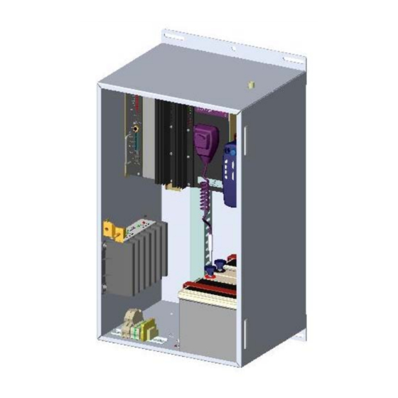
Federal Signal UltraVoice Installation and Operation Manual MOUNTING HOLES (TOP & BOTTOM FLANGES) UV400 AMPLIFIERS UVARM I/0 MODULE (OPTIONAL) CONTROL MODULE TYPE N-FEMALE ANTENNA CONNECTOR TRANSCEIVER DC POWER CONNECTIONS, FUSING & SPEAKER INTRUSION SWITCH FIELD WIRING. (BEHIND COVER PLATE) BATTERY CHARGER 230/115VAC STEPDOWN TRANSFORMER (240 MODELS ONLY) -
Page 14: Figure 1.2 - Control And Amplifier Identification
Federal Signal UltraVoice Installation and Operation Manual Control Amplifier Figure 1.2 – Control and Amplifier Identification GENERAL DESCRIPTION... -
Page 15: Figure 1.3 - Uvarm Identification
Federal Signal UltraVoice Installation and Operation Manual Figure 1.3 – UVARM Identification GENERAL DESCRIPTION... -
Page 16: Figure 1.4 - Uvloc Identification
Federal Signal UltraVoice Installation and Operation Manual Figure 1.4 – UVLOC Identification GENERAL DESCRIPTION... -
Page 17: Motherboard Description
Federal Signal UltraVoice Installation and Operation Manual 1.4 Motherboard Description The Motherboard for the UVIC is a scaled down 800 Watt version of the 3200 Watt UltraVoice product. The board is primarily a passive back plane that provides the electrical connections between the Microprocessor Control board, the Audio and Relay output board, and the UV400 amplifiers. -
Page 18: Unit Type
Federal Signal UltraVoice Installation and Operation Manual Unit Type The Unit Type is set to the type of siren this unit is controlling, and is usually determined by the number of cells in the speaker array. When setting up the unit type, the user selects from a menu with the following choices: 1 - UV400 Amplifier, 400 Watts total power 2 - UV400 Amplifiers, 800 Watts total power... -
Page 19: Rf Frequency
Federal Signal UltraVoice Installation and Operation Manual RF Frequency For units equipped with the optional integral radio receiver, the RF Frequency configuration parameter sets the frequency of the radio channel. Changing this parameter from its factory setting may require re-alignment of the radio for maximum performance. -
Page 20: Security Key
Federal Signal UltraVoice Installation and Operation Manual Security Key For MSK activated units, the Security Key is a unique number assigned to the system that prevents nearby systems operating on the same RF frequency from interfering. Like the 128-bit encryption key, the Security Key is programmed during the flashing of the microprocessor and must match the encoder. -
Page 21: Available Functions
Federal Signal UltraVoice Installation and Operation Manual Available Functions: Disarm Report Master Reset Cancel PA Output Quiet Test Low Power Mode Hi Power Mode Zone A (Rotating Sirens Only) Zone B (Rotating Sirens Only) Zone C (Rotating Sirens Only) Zone D (Rotating Sirens Only) Wail Pulsed Wail Alt Wail... -
Page 22: Specifications
Federal Signal UltraVoice Installation and Operation Manual SECTION II 2. SPECIFICATIONS 2.1 Electrical AC Input Voltage 120 or 240VAC 50-60Hz* (*two separate models) AC Input Current 5 amps maximum Battery Input Voltage 20-28VDC, 24 volts (nominal) Battery Current 120 mA standby current, +18 to 22 amps for each amplifier module running, 50A maximum Battery Capacity... -
Page 23: Battery
Federal Signal UltraVoice Installation and Operation Manual 2.3 Battery Battery Voltage (72F) 27.2VDC nominal Recommended Batteries: NorthStar model: NFB12-180 HAZE model: HZB12-44 Type VRLA Rating 44A/H minimum CAUTION: Substituting batteries may be hazardous and will void warranty. Use specified batteries only. 2.4 Controller Serial &... -
Page 24: Audio Output To Amplifiers
Federal Signal UltraVoice Installation and Operation Manual Audio Output to Amplifiers Output Voltage Swing >9V peak-to-peak (p-p) Maximum Load 600 ohms Total Harmonic Distortion < 10% w/1KHz sine-wave 2.5 Motherboard Relay Output Contact Rating 30VDC, 15A 600 Ohm Balanced Line Port Audio Input Level 0.10 to 2 volts p-p to make 1 volt p-p TP10... -
Page 25: Expansion Slot
Federal Signal UltraVoice Installation and Operation Manual Expansion Slot The expansion slot contains the same connector pin-out as the controller slot. Signals available: Two I C Ports 600 Ohm Balanced Port +5VDC +24VDC AUDIO-A and AUDIO-B Open-Collector Output (for Rotator Relay) Charger Indicator 4 Remote Sensor Inputs 8 Remote Activation Inputs... - Page 26 Federal Signal UltraVoice Installation and Operation Manual Pin 2 24VDC Unfiltered 24VDC Output (for accessories) Pin 1 Ground Pin 2 24VDC Filtered 24VDC Output (for radio power 12V DC-DC converter) Pin 1 Ground Pin 2 +24VDC JP8-JP10 Not Used JP11 20A DC, Normally Open Relay Output: JP12 600 ohm Transformer Balanced Audio I/O...
- Page 27 Federal Signal UltraVoice Installation and Operation Manual Pins: 5 (-) 5 (+) - 150mA max current for external equipment JP17 Spare Sensor Input Pins: ISO Ground SPR3 -active low SPR4 -active low SPR5 -active low SPR6 -active low JP18 Expansion Port, Secondary Cabinet Pins: Ground C VCC 5...
-
Page 28: Indicators
Federal Signal UltraVoice Installation and Operation Manual JP24 Amplifier 2 Output Pins: 1 - 12 SIG + JP29 Expansion Port, Primary Cabinet Pins: Ground I2C VCC 5 Serial Clock 1 Serial Data 1 Amplifier Audio Signal A Amplifier Audio Signal B Indicators Relay Output LED Fuses... -
Page 29: Figure 2.1 - Motherboard Outline Drawing
Federal Signal UltraVoice Installation and Operation Manual Figure 2.1 - Motherboard Outline Drawing SPECIFICATIONS... -
Page 30: Controller Front Panel Controls, Jacks, Switches And Indicators
Federal Signal UltraVoice Installation and Operation Manual 2.7 Controller Front Panel Controls, Jacks, Switches and Indicators Controls: DV GAIN Internal Digital Voice Level sufficient to drive TP1 or TP2 into clipping TX GAIN Transmitted Audio Adjustable from 50mv to 1 volt peak-to-peak (p-p) REC GAIN Received Audio Level 150 mV to 3 volts p-p MIC GAIN... -
Page 31: Indicators
Federal Signal UltraVoice Installation and Operation Manual Manual Activation Switches: QTY 8, activate with a hold time >0.50 seconds Indicators: Receive Serial Data & receipt of radio channel modulation Transmit Serial Data & DTMF & Digital AUDIO A Audio present on Channel A AUDIO B Audio present on Channel B Unit Armed indicator... -
Page 32: Control Unit Connector Configuration
Federal Signal UltraVoice Installation and Operation Manual Control Unit Connector Configuration Refer to tables below for description of connectors in control assembly. Connectors for 2005141 PCB CONNECTOR DESIGNATION PURPOSE On-Board Receiver Module Connector Pins: Ground Clock Data Latch Enable Carrier Detect Not De-Emphasized Receive Audio Flat Receive Audio Inter Board Connections... - Page 33 Federal Signal UltraVoice Installation and Operation Manual Connectors for 2005141 PCB – Continued CONNECTOR DESIGNATION PURPOSE CTCSS Connector Pins: RX Audio In Ground 8VDC for CTCSS Board Audio Switch TX CTCSS Tone 600 Ohm Configuration Jumper -See motherboard JP15 and JP12 Pins: Jumpered is active Activation audio from JP12 PA mode...
-
Page 34: Audio Power Amplifier Modules Model (Uv400)
Federal Signal UltraVoice Installation and Operation Manual 2.8 Audio Power Amplifier Modules Model (UV400) Input voltage 24VDC nominal 28VDC maximum Input Current Siren mode @ 24VDC w/1KC square-wave into 11 ohms: <20 amps Input Current Voice Mode @ 24VDC w/1KHz tone set to 67VRMS into 11 ohms: <24 amps Standby current at amps turned off <10 milliamps... -
Page 35: Audio And Relay Output Card Option (2005300)
Federal Signal UltraVoice Installation and Operation Manual 2.9 Audio and Relay Output Card Option (2005300) Input voltage 13.5 - 30 Input current 200 mA maximum Balanced 33 ohm output Adjustable from 0.2 – 1.9VRMS Balanced 600 ohm output Adjustable from 0.2 – 3VRMS or -12 to +11dB, surge protected Single-ended or balanced Adjustable from 0.2 –... -
Page 36: Indicators
Federal Signal UltraVoice Installation and Operation Manual JP4, 3 pin shorting jumper Short pins 1 & 2 to select channel A audio for JP3 output Short pins 2 & 3 to select channel B audio for JP3 output JP5, 3 pin shorting jumper Short pins 1 &... -
Page 37: Model Uvloc
Federal Signal UltraVoice Installation and Operation Manual 2.10 Model UVLOC Operating Voltage: 20 - 32VDC Operating Current: < 25 mA Digital Outputs: Four BCD encoded, 1 amp current sink maximum Audio Output: 600 ohm balanced, adjustable 700 mVpp to 5 Vpp Maximum Distance between Control Panel and UV: Approx 1/2 mile of cable, </= 200 ohms of cable... -
Page 38: Alarm Panel Interface Connectors
Federal Signal UltraVoice Installation and Operation Manual Alarm Panel Interface Connectors JP2, JP3, JP4, JP5, JP7, JP7 & JP8, six RJ45s and one 8 position terminal strip wired in parallel; 1 – Ground 2 – Power 3 – Direction Input # 0 4 –... -
Page 39: Environmental
Federal Signal UltraVoice Installation and Operation Manual 2.12 Environmental Operating Temperature -30°C - +65°C Humidity 0-98% non-condensing Notes: 1. The UVIC can operate throughout this temperature range provided the battery temperature is maintained at -18°C or higher. 2. The UVIC housing carries a NEMA 1 rating 2.13 Physical UV400 amplifiers 10.5”... -
Page 40: Uvic Operation
SECTION III 3. UVIC OPERATION 3.1 Hardware General Description microcomputer controlled control board. The UVIC contains a card cage with four The back-plane (motherboard) contains plug-in boards consisting connectors and terminal blocks for controller slot, one optional accessory wireless interconnection of the other slot and two amplifier slots. -
Page 41: Local Public Address
3.3 Local Public Address 3.6 Remote-Landline Activation The operator has the ability to give local Terminal block JP14 at the bottom of the Public Address (PA) messages using system motherboard is the Remote model MNC-MC microphone Activation input. There are eight inputs provided. -
Page 42: Sensor Inputs And Isolated Sensor Power
Sensor Power 3.7 Sensor Inputs and Isolated Intrusion: Alerts the controller when one Terminal block JP15 at the bottom of the of the unit’s doors has been system motherboard is the Sensor opened. Low is intrusion pass Inputs. These are activated by a short to “Common”. -
Page 43: Spare Sensor Inputs
3.8 Spare Sensor Inputs 3.10 Quiet Test The inputs at JP17 are not used in This option enables acoustically quiet typical applications with UVIC tests to be performed on the siren controller. control and siren speaker array. Quiet Test uses a 20 kHz tone to quietly test the tone generators, amplifiers, and 3.9 Two-Way Status Monitoring speaker drivers. -
Page 44: Battery Charger
3.11 Battery Charger 12VDC stage separately. Each stage can consist of more than one battery in parallel. See “Specifications Section,” The battery charger is a smart charger “Battery,” required quantity that monitors battery conditions, batteries. The two stages of batteries temperature, and varies charge rate. -
Page 45: Uvloc
3.12 UVLOC re-record the previous message each time the ACTIVATE button is pressed. Up to 2 minutes of recording time is All potential users should be properly available for the record function. The trained on the use of the control panel. PLAYREC function will play-back the digitally recorded message. -
Page 46: System Planning
SECTION IV SYSTEM PLANNING locally. Landline control can be used 4.1 Control Unit through normally open contact switches. Connections should be made directly to the motherboard terminal blocks. The The information in this section provides control can also be remotely activated via the user with guidelines necessary for the optional radio receiver or an external installation. -
Page 47: Uvloc Placement
assistance to properly place your warning equipment. The speakers connected to the UVIC may be selectively turned on using amplifier zones. zones programmed into the UVIC to allow Zone 1, Zone 2 or all amp zones to be activated. Amp Zones are programmed using the AZ commands in SFCDWARE. -
Page 48: Installation
SECTION V INSTALLATION cabinet mounting details in section 5.3 and the electrical installation material list WARNING in section 5.4. Read all Safety Notices at the beginning of this manual before installation. 5.1 UVIC Siren Controller Installation Reference Drawings This section contains reference drawings to assist with installation. -
Page 49: Figure 5.2 - Uvic Cabinet Dimensional Outline Drawing
Figure 5.2 - UVIC Cabinet Dimensional Outline Drawing INSTALLATION... -
Page 50: Figure 5.3 - Uvic Wiring Diagram
Figure 5.3 – UVIC Wiring Diagram INSTALLATION... -
Page 51: Figure 5.4 - Uvic Battery Connections
Figure 5.4 – UVIC Battery Connections INSTALLATION... -
Page 52: General Mounting Guidelines For All Applications
5.2 General Mounting Guidelines For All Applications These general installation instructions If the mounting surface is not flat, the are pertinent to all installations. Specific cabinet may require shimming to mounting methods required keep the cabinet square. installation materials are described in the next section. -
Page 53: Uvic Installation Material List And Installation Guidelines
5.3 UVIC Installation Material List and Installation Guidelines following material lists mounting methods, other options, local guidelines describe basic installation national electrical codes, etc. details required to install the UVIC Therefore, this list should be used as a cabinet. This list will vary depending on reference guideline only. -
Page 54: Wood Stud Wall Mounting Guidelines
Wood Stud Wall Mounting Materials Material Description Purpose 3/8” x 3” Lag Backboard & bolts cabinet mounting bolts 24” x 36” x Mounting ¾” B/C or backboard better plywood Construction Mounting adhesive backboard attachment Wood Stud Wall Mounting Guidelines: 1. Locate the wall studs for attaching the 4. -
Page 55: Metal Stud Wall Mounting Guidelines
Metal Stud Wall Mounting Materials Material Description Purpose 3/8” x 3” lag Cabinet bolts mounting bolts 24” x 32” x ¾” Mounting B/C or better backboard plywood #10 x 3” metal Backboard stud screws mounting Construction Backboard adhesive mounting Metal Stud Wall Mounting Guidelines: 1. -
Page 56: Installer Supplied Uvic Electrical Installation Material List
5.4 Installer Supplied UVIC Electrical Installation Material List Material Description Purpose 30 amp/250V/ 2 Pole Solid Optional Electrical Disconnect Neutral/Fused Disconnect w/ Ground Kit/ NEMA 1 Rating/ Lockable Cover Tang/ Lockable Operator 15A FRNR Fuse Fuses For 120V Service 10A FRNR Fuse Fuses For 240V Service 12-14 AWG White Wire AC Neutral from disconnect... -
Page 57: Electrical Connections
DIN Rail Terminal Blocks 5.5 Electrical Connections These points provide a convenient location for making electrical connections. A small Install siren electrical system screwdriver must be pushed into the square compliance with local electrical codes and opening in the terminal block to open the NEC recommendations. -
Page 58: Wiring Guidelines For 240Vac Electrical Service
6. Optionally, connect a green ground wire cabinet or run a ground lead from the from the breaker panel earth ground to external 3/8” ground stud on the UVIC the green ground block in the UVIC cabinet to earth ground. cabinet or run a ground lead from the external 3/8”... -
Page 59: Antenna Types
batteries 1 & 2 last. Use an anti- antenna mast to be at least 2’ away oxidant to protect the terminals. from any grounded metal objects. 4. Verify battery connections 2. Mount the antenna to a flat, secure tightened securely to make proper metal structure with at least 225”... -
Page 60: Final Vswr Tuning
3. Insert the elements into their respective 1. Before final installation of the antenna, locations through the boom, starting with temporarily set it up in a clear area at R1 (the reflective element) in the hole least six feet above the ground. closest to the mounting holes. -
Page 61: Yagi Antenna Mounting
good, due to the DMM not having the frequencies). If that does not take care ability to check the cable at high of the problem, replace the antenna. frequencies. If that does not take care of the problem, replace the antenna. 5.10 Omni Antenna Installation Yagi Antenna Mounting Fiberglass, no tune models... -
Page 62: Figure 5.5 - Yagi Antenna Installation Example
Figure 5.5 - Yagi Antenna Installation Example INSTALLATION... -
Page 63: Figure 5.6 - Omni Antenna Installation Example
Figure 5.6 - Omni Antenna Installation Example INSTALLATION... -
Page 64: Figure 5.7 - Antenna Grounding Example
Figure 5.7 – Antenna Grounding Example INSTALLATION... -
Page 65: Speaker Connections
5.11 Speaker Connections The speaker connections are located on the bottom right hand side of the motherboard. There are two 12 position removable connectors for each of the amplifiers enabling up to 12 pairs of wires to be connected to each amp. The connectors for Amp 1 are located under the card cage. -
Page 66: Optional Uvloc Connections And Wall Mounting
5.15 Optional UVLOC Connections and Wall Mounting Refer to figure 5-9 for the UVLOC mounting hole locations. The UVLOC is typically mounted on a wall approximately 5’ above the ground. The UVLOC requires a CAT5 cable between the UVLOC and the interface board (UVLOC-IM) in the UVIC. -
Page 67: Turning Power On
to turn on the amplifiers and route the 600 ohm audio to the amplifiers. For best results, a well-filtered audio source should be used. The audio cable used should be shielded audio grade cable and the length should be kept as short as possible. Keep away from sources of electrical noise. -
Page 68: Figure 5.9 - Uvloc Interface Wiring Diagram
UVIC Motherboard UVLOC Interface PCB Figure 5.9 - UVLOC Interface Wiring Diagram INSTALLATION... -
Page 69: Figure 5.10 - Uvloc Dimensional Outline
Figure 5.10 - UVLOC Dimensional Outline INSTALLATION... -
Page 70: Figure 5.11 - Uvic25Sd Wiring Diagram
Figure 5.11 – UVIC25SD Field Wiring Diagram INSTALLATION... -
Page 71: Pre-Operation Checkout And Test
SECTION VI 6. PRE-OPERATION CHECKOUT 6.2 Amplifier and Speaker Pre- Operation Checkout AND TEST 1. Refer to Figure 5.4. Measure the DC Warning voltage between battery 1 (-) and battery 2 (+). The voltage should be The following procedures should be at least 25VDC. -
Page 72: Radio Transceiver Adjustment Procedure
6.3 Radio Transceiver Adjustment Procedure 2. Measure the deviation level using service monitor. Note: This procedure previously 3. Adjust level (2005141 completed at factory. Only readjust if controller card front panel) for 3kHz radio re-alignment is required or if the deviation. -
Page 73: 600 Ohm Adjustment Procedure For External Audio Source
e. Ensure tone is not clipped by closure at JP15 pins 10 and 11 viewing waveform with (PTT: Push To Talk) is required to oscilloscope. activate audio mode. b. Adjust the level using the external 2. TX adjustment audio gain adjustment R111 (R111 a. - Page 74 output level. A small straight blade After the levels have been properly screwdriver can be used to adjust the adjusted, verify all other functions microphone sensitivity. The nominal operate properly from the UVLOC level should be set to approximately control panel. zero dBm out of the control panel.
-
Page 75: Field Test Data Sheet
UVIC Field Test Data Customer: Project Number: Date: Contact Person: Phone: Second Phone: Radio Shop: Contact: Phone: Siren Type: S/N: Voltage: Controller Type: Antenna: Omni Yagi A/C Service: O.H. Cabinet Mounted U.G. External Mounted CPU Software: Program file: SMV: Radio Information: Low Band Trunk 12.5 KHz 25 KHz... -
Page 76: Maintenance
FWS Service Department protection avoid excessive Signal Division exposure. Federal Signal Corporation 2645 Federal Signal Drive Before servicing or maintaining, ensure University Park, Illinois 60466 that remote activation cannot occur and (800) 524-3021 disconnect power to the UVIC. MAINTENANCE... -
Page 77: Control Unit Preventive Maintenance
motherboard) to eliminate output WARNING from the speaker array. The sound output of speakers is 2. Activate each of the signals and capable of causing permanent hearing observe the signal indicators on the damage at short distances. Therefore, control module and the amplifiers. ALWAYS wear hearing protection when performing tests or maintenance on the 3. -
Page 78: Troubleshooting
7.3 Troubleshooting PROBLEM ACTION NO RADIO DECODE A. Unit is not programmed to recognize that particular code sequence (or) Signal is not being received properly. B. Verify programming is correct. Check the received audio signal quality at the RX test pin on the front of the control board. -
Page 79: Options
SECTION VIII commands activate stored 8. OPTIONS message. The only adjustment available Digital Voice potentiometer, which adjusts the audio output level. 8.1 Radio Control The UVIC can be activated by a radio 8.3 UVIC25ST Option signal when optional radio transceiver is incorporated into the When purchased, the UVIC25ST allows Control Unit. -
Page 80: Uvloc Option
ohm balanced or single-ended line level output and four SPDT relay outputs. 8.7 Installation of User Supplied The level of each audio output is Radio Receivers independently adjustable. Each audio relay output individually CAUTION addressable allowing each output to be Improper installation of radio control activated at different times. - Page 81 1. AUDIO – ULTRAVOICE active. The radio carrier detect signal controller Receive Audio Input is useful for controlling live PA. should be connected to the de- When the C.D. signal is removed emphasized Audio Output of the from controller over radio.
-
Page 82: Final Assembly Drawing And Parts List
SECTION IX 9. Final Assembly Drawing and Parts List Figure 9.1 – UVIC Final Assembly and Parts List (Page 1 of 2) - Page 83 Figure 9.1 – UVIC Final Assembly and Parts List (Page 2 of 2)
-
Page 84: Figure 9.2 - Uvic25St Wiring Detail
Figure 9.2 – UVIC25ST Wiring Detail UVIC Final Assembly and Parts List...
Need help?
Do you have a question about the Personnel Alerting System and is the answer not in the manual?
Questions and answers