
Related Manuals for Federal Signal Corporation PAGASYS GEN II P-SYS-G


Summary of Contents for Federal Signal Corporation PAGASYS GEN II P-SYS-G
- Page 1 PAGASYS GEN II ® Public Address and General Alarm System Model: P-SYS-G Description, Installation, Operations and Maintenance Manual 25500458 Rev. B0 1019 Printed in U.S.A. © Copyright 2018-2019 Federal Signal Corporation...
- Page 2 A copy of this limited warranty can also be obtained by written request to Federal Signal Corporation, 2645 Federal Signal Drive, University Park, IL 60484, email to info@fedsig.com or call +1 708-534-3400.
-
Page 3: Table Of Contents
Contents 1.0 Safety Messages..............................14 2.0 General Description ............................16 2.1 Introduction ............................16 2.2 Overview ...............................16 2.3 System Architecture ..........................16 2.4 Features ...............................18 2.5 Components ............................19 2.5.1 Cabinet ..........................19 2.5.2 Controller Chassis ........................19 2.5.3 System Controller Backplane (20000170) ................21 Backplane 2.5.4 Controller Specifications ...................21 2.5.5 Power Supply Card (120/240 Vac) (P-ADPS-G) .............. - Page 4 3.3.1 Beacon Monitored Module Specifications (P-BK-MON-G) ........... 46 3.4 Relay Output Card (P-SPDT-G) ......................46 3.4.1 Relay Output Card Specifications (P-SPDT-G) ..............47 3.5 Fan Control and Monitoring Card (P-FCMC-G) ..................48 3.5.1 Fan Control and Monitoring Card Specifications (P-FCMC-G) ..........49 3.6 Monitored Input Module (P-MONIC-G) ....................50 3.6.1 Monitored Input Module Specifications (P-MONIC-G) ............
- Page 5 5.3.3 Preparing Amplifier Installation and Removal ...............69 5.3.4 Removing the Amplifier Chassis ...................69 5.3.5 Installing the Amplifier Chassis .....................69 5.3.6 Replacing the Internal Cards ....................69 5.3.7 Removing the Amplifier Card ....................70 5.3.8 Installing the Amplifier Card ....................71 5.3.9 Removing the ISMT Card (Optional) ..................73 5.3.10 Installing the ISMT Card (Optional) ..................73 6.0 Installing and Configuring the I/O Cards .......................74 6.1 Main Distribution Frame (MDF) ......................74...
- Page 6 6.9.2 Installing and Configuring the Amplifier Audio Distribution Cards (P-AADCx-G) ....84 6.10 Fan Wiring Termination Card (P-FWTC-G) ..................85 6.10.1 Removing the Fan Wiring Termination Card (P-FWTC-G) ..........85 6.10.2 Installing and Configuring the Fan Wiring Termination Card ..........85 6.11 IS Barrier Board (P-IS-BARRIER-G) ....................86 6.11.1 Removing the IS Barrier Board (P-IS-BARRIER-G) ............
- Page 7 14.0 Configuring a Broadcast..........................114 14.1 Creating a new broadcast for PAGASYS GEN II ................114 14.2 Adding a new button and LED to a control panel ................115 15.0 Programming PABX Interface ........................117 15.1 Configuring the Miscellaneous Card ....................117 15.2 Configuring the Miscellaneous Card ....................
- Page 8 Figures Figure 1 System Architecture ..........................17 Figure 2 PAGASYS GEN II Cabinet ........................19 Figure 3 Controller Chassis (P-NET-G) ........................20 Figure 4 System Controller Backplane (20000170) ....................21 Figure 5 Power Supply Card (120/240 Vac)(P-ADPS-G) ..................22 Figure 6 Controller Card (DSP/ARM) (P-CPC-G) ....................24 Figure 7 Amplifier Audio Mux Card (P-AAMC-G) ....................26 Figure 8 Internal AP Mux Card (P-IAMC-G) ......................27 Figure 9 External AP Mux Card (P-EAMC-G).......................28...
- Page 9 Figure 27 Passive Terminal Block Card (P-PTBC-G) ..................52 Figure 28 Cable Power Injector I/O Card (P-CPIC-G) ..................53 Figure 29 P-AADC1-G and P-AADC1-G-01 Cards ....................54 Figure 30 P-AADC2-G and P-AADC2-G-01 Cards ....................54 Figure 31 P-AADC4-G and P-AADC4-G-01 Cards ....................55 Figure 32 P-AADC8-G and P-AADC8-G-01 Cards ....................55 Figure 33 Fan Wiring Termination Card (P-FWTC-G) ..................56 Figure 34 IS Barrier Board (P-IS-BARRIER-G) ....................58 Figure 35 Picture of Desktop Access Panel ......................59...
- Page 10 Figure 54 Jumpers configured to support a Standby Amplifier ...............91 Figure 55 Defining an Amplifier Chassis ......................94 Figure 56 Removing the chassis mounting screws ...................95 Figure 57 Removing the cover screws ........................95 Figure 58 Inserting four jumpers in the left-most position ................96 Figure 59 Fourth amplifier slot ..........................96 Figure 60 Standby amp bus ports on the Amplifier Chassis ................97 Figure 61 Left (Audio) MDF Panel ........................98...
- Page 11 Tables Table 1 Controller Models .............................20 Table 2 Environmental and Physical for the Controller Chassis (P-NET-G) ............ 20 Table 3 Controller Cards ............................21 Table 4 Environmental and Physical for the Controller Backplane (20000170) ..........21 Table 5 Environmental and Physical for the Controller Power Supply Cards (P-ADPS-G and P-ADPS-G-01) Table 6 Electrical Specifications for the Power Supply Card (P-ADPS-G) ............
- Page 12 Table 26 Environmental and Physical for the Digital Input Card (P-16DIN-G) ..........45 Table 27 Dry Contact Mode for the Digital Input Card (P-16DIN-G) ..............45 Table 28 24 V PLC Contact Mode for the Digital Input Card (P-16DIN-G) ............45 Table 29 Environmental and Physical for the Beacon Monitored Module (P-BK-MON-G) ......
- Page 13 Table 52 I/O and Terminal Block Models ......................131 Table 53 PAGASYS GEN II Optional Accessory Models ..................131 Table 54 PAGASYS GEN II Access Panel and IS Barrier Models ..............132 Table 55 Standard Control Cabinet Models ......................133 Table 56 PAGASYS GEN II Controller Service Parts ..................134 Table 57 PAGASYS GEN II Amplifier Service Parts ..................134 Table 58 PAGASYS GEN II I/O and Terminal Block Service Parts ..............
-
Page 14: Safety Messages
Safety Messages 1.0 Safety Messages This equipment should be installed, adjusted, and serviced by qualified technicians familiar with the construction and operation of the equipment and the hazards involved. Read, understand, and follow all of the warnings provided in the Safety Messages section of this instruction manual, before servicing the system. - Page 15 Safety Messages • After removing a printed circuit card containing a static sensitive component, place the printed circuit card only on conductive or anti-static material (such as conductive foam, conductive plastic, or aluminum foil). Do not use ordinary Styrofoam or ordinary plastic.
-
Page 16: General Description
General Description 2.0 General Description 2.1 Introduction This document is a description of the features, installation, operation, and maintenance of the PAGASYS GEN II Public Address and General Alarm System. The PAGASYS GEN II system provides robust public address and general alarm services for use in a variety of environments, including, but not limited to, offshore petrochemical facilities, onshore petrochemical facilities, and onshore industrial facilities. -
Page 17: Figure 1 System Architecture
General Description The system has field equipment, including: • Loudspeakers: Convert the electrical audio signal from the amplifiers into a corresponding sound. • Beacons and Status Lamps: Supplement audio broadcasts in areas of high ambient noise with visual signaling. • Access Panels and Microphone Stations: Include microphones and push-button controls. -
Page 18: Features
General Description 2.4 Features The PAGASYS GEN II system has the following features: • System Manager application provides real-time system status, including event logs, system activity, broadcast status, impedance speaker monitoring, fan flow, and amplifier temperature status • A single Controller can support up to thirty-two 1200 W Amplifier Chassis •... -
Page 19: Components
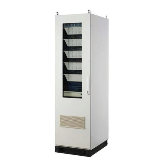
General Description 2.5 Components 2.5.1 Cabinet The PAGASYS GEN II Cabinet is available in 120 Vac or 240 Vac versions. The cabinet models include the following: • Controller Chassis (except for the P-SYS-G-AMPS-5KW-x cabinets) • Standard I/O cards (See Table 23.) •... -
Page 20: Figure 3 Controller Chassis (P-Net-G)
General Description Figure 3 Controller Chassis (P-NET-G) Access Access Miscellaneous Panel Panel Card Audio Mux 1 Mux 2 Power Processor Supply Interface Card Card Card Table 1 Controller Models Model Description P-NET-G Controller Chassis K20000170 Controller Backplane Service Model Table 2 Environmental and Physical for the Controller Chassis (P-NET-G) Operating Temperature -10 to +55°C Humidity... -
Page 21: System Controller Backplane (20000170)
General Description 2.5.3 System Controller Backplane (20000170) The System Controller Backplane (20000170) provides the electrical power and signal interconnections between the various controller cards to form a complete System Controller. (See Figure 4.) NOTE: The service model for the System Controller Backplane is K20000170. Figure 4 System Controller Backplane (20000170) Table 3 lists the PAGASYS GEN II controller cards that can be inserted into the backplane. -
Page 22: Power Supply Card (120/240 Vac) (P-Adps-G)
General Description 2.5.5 Power Supply Card (120/240 Vac) (P-ADPS-G) The Power Supply card is the primary power supply for the AC-powered Controller Chassis. (See Figure 5.) This card supports universal 90 to 264 Vac voltage input, with onboard AC fusing. The Controller Power Supply card addresses the system controller chassis’s various DC power needs. -
Page 23: Controller Processor Card (Dsp/Arm) (P-Cpc-G)
General Description Table 6 Electrical Specifications for the Power Supply Card (P-ADPS-G) AC supply input voltage range 85–264 V AC supply input Frequency 50/60 Hz Max Input Current Draw 115 V input 3.2 A 230 V input 1.6 A DC power supply rail Parameter Output Voltage / Current 24 Vdc rail Output voltage range... -
Page 24: Figure 6 Controller Card (Dsp/Arm) (P-Cpc-G)
General Description The Controller Processor card uses a watchdog circuit to monitor processor operation and reset the processor if the watchdog timer is not updated. NOTE: The service model for the System Controller Processor card is K-P-CPC-G. Figure 6 Controller Card (DSP/ARM) (P-CPC-G) Table 7 Environmental and Physical for the Controller Processor Card (P-CPC-G) Operating Temperature -10 to +55°C... -
Page 25: Amplifier Audio Mux Card (P-Aamc-G)
General Description 2.5.7 Amplifier Audio Mux Card (P-AAMC-G) The Amplifier Audio Multiplexer card (P-AAMC-G) provides an interface to connect a System Controller to its associated Amplifiers. (See Figure 7.) In addition, the P-AAMC-G provides the interface needed to connect two System Controllers to form N+1 redundant PAGASYS GEN II system. -
Page 26: Internal Ap Mux Card (P-Iamc-G)
General Description Figure 7 Amplifier Audio Mux Card (P-AAMC-G) Table 8 Environmental and Physical for the Amplifier Audio Multiplexer Card (P-AAMC-G) Operating Temperature -10 to +55°C Humidity 0-98% non-condensing P-AAMC-G Dimensions (H x W x L) 45 mm x 343.9 mm x 152.25 mm Weight 0.41 kg/0.90 lb 2.5.8 Internal AP Mux Card (P-IAMC-G) -
Page 27: Figure 8 Internal Ap Mux Card (P-Iamc-G)
General Description The P-IAMC-G communicates with remote Access Panels or Microphone Stations through eight electrically isolated full duplex RS422 serial ports. When Access Panels need to communicate with the P-IAMC-G card using field wiring, use the Passive Terminal Block card (P-PTBC-G) to convert the field wiring to a compatible RJ45 cable that can connect directly to the P-IAMC-G card. -
Page 28: External Ap Mux Card (P-Eamc-G)
General Description 2.5.9 External AP Mux Card (P-EAMC-G) The External Access Panel Multiplexer card (P-EAMC-G), when combined with two Access Panel Aggregator cards (P-APIC-G), can provide the interface to connect up to 16 Access Panels or Microphone Stations to a System Controller. (See Figure 9.) Install the P-EAMC-G card in the System Controller Chassis in AP MUX slots 1 or 2, or in both slots. -
Page 29: Miscellaneous I/O Card (P-Cmc-G)
General Description Table 10 Environmental and Physical for the External AP Mux Card (P-EAMC-G) Operating Temperature -10 to +55°C Humidity 0-98% non-condensing P-EAMC-G Dimensions (H x W x L) 45 mm x 343.9 mm x 171.9 mm Weight 0.51 kg/1.13 lb 2.5.10 Miscellaneous I/O Card (P-CMC-G) The Miscellaneous I/O card (P-CMC-G) (see Figure 10) provides several input/output (I/O) interfaces for the System Controller:... -
Page 30: I/O Interface Card (P-Ioic-G)
General Description Figure 10 Miscellaneous I/O Card (P-CMC-G) Table 11 Environmental and Physical for the Miscellaneous I/O Card (P-CMC-G) Operating Temperature -10 to +55°C Humidity 0-98% non-condensing P-CMC-G Dimensions (H x W x L) 45 mm x 343.9 mm x 171.9 mm Weight 0.38 kg/0.84 lb 2.5.11 I/O Interface Card (P-IOIC-G) -
Page 31: Amplifier Chassis
General Description Figure 11 I/O Interface Card (P-IOIC-G) Table 12 Environmental and Physical for the I/O Interface Card (P-IOIC-G) Operating Temperature -10 to +55°C Humidity 0-98% non-condensing P-IOIC-G Dimensions (H x W x L) 45 mm x 343.9 mm x 171.9 mm Weight 0.29 kg/0.63 lb 2.5.12 Amplifier Chassis... -
Page 32: Figure 12 Amplifier Chassis
General Description Table 13 Amplifier Models Model Description 20000154 Amplifier Signal Backplane 20000155 Amplifier Power Backplane 20000150 300 W Amplifier Card P-ISMT-G ISMT Line Card (Optional) The Amplifier Chassis models are listed in the following table. Table 14 Amplifier Chassis Models Model Description P-A250-G... -
Page 33: Amplifier Specifications
General Description Figure 13 Amplifier Chassis Card Layout (P-A1000-G) Amplifier Power Backplane Amplifier Board 70 V/100 V Transformer ISMT Card Amplifier Signal Backplane 2.5.13 Amplifier Specifications Table 15 Environmental and Physical for the Amplifier Operating Temperature -10 to +55°C Humidity 0–98% non-condensing Amplifier Chassis Dimensions (H x W x L) 177 mm x 483 mm x 478 mm Weight... -
Page 34: Amplifier Front Panel
General Description Table 17 Power Requirements per Amplifier Card (AC Model) Universal AC Power Line Input 90–264 Vac, 50/60 Hz Power Consumption at 230 Vac, 300 W output 350 W Efficiency at 230 Vac 85.6% Power Consumption at 120 Vac, 300 W output 355 W Efficiency at 120 Vac 84.6%... -
Page 35: Amplifier Front Chassis
General Description Fields Description High Yellow, indicates that the temperature of the internal temperature sensor Temperature has exceeded 80°C. The module may stop operation if the temperature continues to rise and reaches a cut-out temperature level. Load Fault Yellow, indicates that the latest self-diagnostic test indicated the output speaker impedance is out of its calibration range, or that the Earth fault was detected. -
Page 36: Amplifier Signal Backplane (20000154)
General Description on amplifier fan cooling operation. Figure 15 Amplifier Front Chassis Amplified IN OUT Audio Out 6 Channels of low-level Standby audio and 2 channels of Amp Bus RS485 data 2.6.2 Amplifier Signal Backplane (20000154) The Amplifier Signal Backplane (20000154) provides control interfaces for the Amplifier Chassis. -
Page 37: Amplifier Power Backplane (20000155)
General Description Table 19 Environmental and Physical for the Amplifier Signal Backplane (20000154) Operating Temperature -10 to +55°C Humidity 0-98% non-condensing 20000154 Dimensions (H x W x L) 30 mm x 389 mm x 138 mm Weight 0.26 kg/0.58 lb 2.6.3 Amplifier Power Backplane (20000155) The Amplifier Power Backplane (20000155), provides power interfaces for the Amplifier Chassis. -
Page 38: Amplifier Card (20000150)
General Description Table 20 Environmental and Physical for the Amplifier Power Backplane (20000155) Operating Temperature -10 to +55°C Humidity 0-98% non-condensing 20000155 Dimensions (H x W x L) 18 mm x 389 mm x 87 mm Weight 0.19 kg/0.42 lb 2.6.4 Amplifier Card (20000150) The Amplifier Card (20000150), shown in Figure 18, provides 70 V or 100 V audio signaling output at a max power level of 300 W. -
Page 39: Ismt Card (P-Ismt-G)
General Description The picture below shows the 100 V Amplifier Card 20000150. Figure 18 Amplifier Card (20000150) Table 21 Environmental and Physical for the Amplifier Card (20000150) Operating Temperature -10 to +55°C Humidity 0-98% non-condensing 20000150 Dimensions (H x W x L) 65 mm x 410 mm x 169 mm Weight 0.75 kg/1.65 lb... -
Page 40: Figure 19 Ismt Card (P-Ismt-G)
General Description Configuring for non-ISMT To configure a group of Amplifier Chassis sharing a common Standby Amplifier Bus for non-ISMT Amplifier Standby routing: • You may configure only one Amplifier Chassis in the Amplifier group to contain a Standby Amplifier. •... -
Page 41: Figure 20 Ismt Connector On The Amplifier Signal Backplane
General Description Figure 20 ISMT Connector on the Amplifier Signal Backplane ISMT connector If the amplifier in slot 4 is to be the Standby Amplifier, fit the four jumpers on the left side. NOTICE: If an ISMT card is installed in the ISMT slot, remove the jumpers from the board to avoid damaging the ISMT board. -
Page 42: I/O And Terminal Block Cards
I/O and Terminal Block Cards 3.0 I/O and Terminal Block Cards The I/O and Terminal Block cards for wire terminations are mounted in an easy access front entry area at the bottom of the Cabinet. (See Table 23.) Table 23 I/O and Terminal Block Models Model Description Card Type... -
Page 43: Figure 21 Access Panel Aggregator I/O Card, Rj45 Connector (P-Apic-G)
I/O and Terminal Block Cards The Access Panel Aggregator I/O card provides termination points for Access Panels. See list of models with attributes below. Table 24 Termination Points Model Number of Access AP Field Connection Type panels supported P-APIC-G Cage clamp terminal block P-APIC-G-01 4 Screw terminal block P-APIC-G-02 8... -
Page 44: Digital Input I/O Card (P-16Din-G)
I/O and Terminal Block Cards Table 25 Environmental and Physical for the Access Panel Aggregator Card (P-APIC-G) Operating Temperature -25 to +55°C Humidity 0-98% non-condensing P-APIC-G Dimensions (H x W x L) 30 mm x 200 mm x 122 mm Weight 0.18 kg/0.40 lb 3.2 Digital Input I/O Card (P-16DIN-G) -
Page 45: Digital Input Card Specifications (P-16Din-G)
I/O and Terminal Block Cards 3.2.1 Digital Input Card Specifications (P-16DIN-G) Table 26 Environmental and Physical for the Digital Input Card (P-16DIN-G) Operating Temperature -25 to +55°C Humidity 0-98% non-condensing Amplifier Chassis Dimensions (H x W x L) 23 mm x 200 mm x 122 mm Weight 0.18 kg/0.40 lb Table 27 Dry Contact Mode for the Digital Input Card (P-16DIN-G) -
Page 46: Beacon Monitored Module Specifications (P-Bk-Mon-G)
I/O and Terminal Block Cards Figure 23 Beacon Monitored Output Module (P-BK-MON-G) 3.3.1 Beacon Monitored Module Specifications (P-BK-MON-G) Table 29 Environmental and Physical for the Beacon Monitored Module (P-BK- MON-G) Operating Temperature -25 to +55°C Humidity 0-98% non-condensing P-BK-MON-G Dimensions (H x W x L) 94 mm x 200 mm x 122 mm Weight 0.91 kg/2.00 lb... -
Page 47: Relay Output Card Specifications (P-Spdt-G)
I/O and Terminal Block Cards State Meaning Pulsed On Microprocessor is sane and executing code Pulsed Off Processor is sane, executing code, and has been addressed by the Controller in the last 30 seconds Fast Blink Node identification mode, Response to PcP command visual node identification •... -
Page 48: Fan Control And Monitoring Card (P-Fcmc-G)
I/O and Terminal Block Cards 3.5 Fan Control and Monitoring Card (P-FCMC-G) The Fan Control and Monitoring card is one of several I/O boards designed specifically for integration into the PAGASYS GEN II system. These I/O boards use a standard control interface, which greatly simplifies the internal wiring of the cabinets. -
Page 49: Fan Control And Monitoring Card Specifications (P-Fcmc-G)
I/O and Terminal Block Cards Figure 25 Fan Control and Monitoring Card (P-FCMC-G) 3.5.1 Fan Control and Monitoring Card Specifications (P-FCMC-G) Table 31 Environmental and Physical for the Fan Control and Monitoring Card (P-FCMC-G) Operating Temperature -25 to +55°C Humidity 0-98% non-condensing P-FCMC-G Dimensions (H x W x L) 44 mm x 200 mm x 124 mm... -
Page 50: Monitored Input Module (P-Monic-G)
I/O and Terminal Block Cards 3.6 Monitored Input Module (P-MONIC-G) The Monitored Input module is one of several I/O modules designed specifically for integration into the PAGASYS GEN II system. (See Figure 26.) These I/O modules use a standard control interface, which greatly simplifies the internal wiring of the cabinets. The Monitored Input module provides 16 electrically isolated (voltage-free contacts fitted with biasing resistors) monitored inputs for the PAGASYS GEN II system. -
Page 51: Monitored Input Module Specifications (P-Monic-G)
I/O and Terminal Block Cards Figure 26 Monitored Input Module (P-MONIC-G) 3.6.1 Monitored Input Module Specifications (P-MONIC-G) Table 35 Environmental and Physical for the Monitored Input Module (P-MONIC-G) Operating Temperature -25 to +55°C Humidity 0-98% non-condensing P-MONIC-G Dimensions (H x W x L) 60 mm x 200 mm x 122 mm Weight (with 2000165 daughter card) 0.17 kg/0.38 lb... -
Page 52: Passive Terminal Block Card Specifications (P-Ptbc-G)
I/O and Terminal Block Cards Figure 27 Passive Terminal Block Card (P-PTBC-G) 3.7.1 Passive Terminal Block Card Specifications (P-PTBC-G) Table 37 Environmental and Physical for the Passive Terminal Block Card (P-PTBC-G) Operating Temperature -25 to +55°C Humidity 0-98% non-condensing P-PTBC-G Dimensions (H x W x L) 30 mm x 200 mm x 79.8 mm Weight 0.35 kg/0.77 lb... -
Page 53: Cable Power Injector I/O Card Specifications (P-Cpic-G)
I/O and Terminal Block Cards Figure 28 Cable Power Injector I/O Card (P-CPIC-G) 3.8.1 Cable Power Injector I/O Card Specifications (P-CPIC-G) Table 38 Environmental and Physical for the Cable Power Injector I/O Card (P-CPIC-G) Operating Temperature -25 to +55°C Humidity 0-98% non-condensing P-CPIC-G Dimensions (H x W x L) 20 mm x 200 mm x 79.8 mm... -
Page 54: Figure 29 P-Aadc1-G And P-Aadc1-G-01 Cards
I/O and Terminal Block Cards The P-AADCx-G cards are connected to the Amplifier Chassis audio power connectors through amplifier audio out cable assemblies. There are several versions of the amplifier audio out cable assemblies, which vary in cable length to accommodate the differing Amplifier Chassis mounting location within the Cabinet. -
Page 55: Amplifier Audio Distribution Terminal Block Specifications (P-Aadcx-G)
I/O and Terminal Block Cards Figure 31 P-AADC4-G and P-AADC4-G-01 Cards Figure 32 P-AADC8-G and P-AADC8-G-01 Cards 3.9.1 Amplifier Audio Distribution Terminal Block Specifications (P-AADCx-G) Table 40 Environmental and Physical for the Amplifier Audio Distribution Terminal Block Cards (P-AADCx-G) Operating Temperature -25 to +55°C Humidity 0-98% non-condensing... -
Page 56: Fan Wiring Termination Card (P-Fwtc-G)
I/O and Terminal Block Cards 3.10 Fan Wiring Termination Card (P-FWTC-G) The Fan Wiring Termination card (P-FWTC-G) is a passive card that provides a termination point for cabinet cooling fans. (See Figure 33.) Two cards are needed in a standard rack: one for the door mounted cooling fans and one for the roof mounted fans. NOTE: The service model for the Fan Wiring Termination card is K-P-FWTC-G. -
Page 57: Table 42 Tb2 Connector Signals (P-Ap-Is-Barrier-G)
I/O and Terminal Block Cards NOTE: The service model for the IS Barrier Board card is K-P-IS-BARRIER-G. The following tables list the TB2, TB3, and J1, and J2 Connector Signals. Table 42 TB2 Connector Signals (P-AP-IS-BARRIER-G) TB2 Pin PAGASYS GEN II PAGASYS GEN II Access Access Panel IS Panel IS BARRIER signal... -
Page 58: Is Barrier Board Specifications (P-Is-Barrier-G)
I/O and Terminal Block Cards Table 45 J2 Connector Signals (P-AP-IS-BARRIER-G) RJ45 PAGASYS GEN II PAGASYS GEN II Access socket Access Panel IS Panel IS BARRIER Signal J2 Pin # BARRIER Signal Name Function RX+B AP RS422 RX+ RX-B AP RS422 RX- TX-B AP RS422 TX- AUDIO+B... -
Page 59: Access Panels
Access Panels 4.0 Access Panels The PAGASYS GEN II system uses new low-profile Access Panels and microphone stations for Intrinsically Safe (IS) and safe area. Each Access Panel provides independent circuitry to support redundant A/B systems and offers a common microphone for the redundant systems. - Page 60 Access Panels • RS422 Data communication with PAGASYS GEN II System Controller through an Internal AP MUX card or an external AP Aggregator card. • Local microphone preamplifier and audio line driver • A 20 kHz monitoring tone, which is used to confirm the audio signal path between microphone station to the PAGASYS GEN II System Controller PAGASYS GEN II (P-SYS-G) Federal Signal www.fedsig.com...
-
Page 61: Removing And Installing The Controller Chassis
Removing and Installing the Controller Chassis 5.0 Removing and Installing the Controller Chassis 5.1 Removing the Controller Chassis 5.1.1 Removing the front cover To remove the front cover, press a latch near the right handle and remove the front cover to expose the dust filter and cable connections. -
Page 62: Removing The Internal Cards
Removing and Installing the Controller Chassis 8. Unplug the cables from the RJ45 jack sockets located on the Miscellaneous I/O card. 9. Unplug the cables from the RJ11 jack sockets located on the Miscellaneous I/O card. 10. Unplug the RS232 cable from the 9-way D socket located on the Miscellaneous I/O card. -
Page 63: Installing The Controller Chassis
Removing and Installing the Controller Chassis 3. Remove the internal cards as per the procedure above. 4. Make a note of all wire labels, colors, positions connected to the backplane. 5. Remove the 5 screws from the backplane’s 4-mm card mount terminal lugs J10 through to J14. -
Page 64: Installing The Controller Chassis
Removing and Installing the Controller Chassis Figure 37 Card Guides in Controller Chassis 2. Carefully press the internal card in vertically downward to mate it with its backplane connectors. 3. Once all internal cards have been installed in their correct locations, refit the Controller Chassis top cover and refit the top cover retaining screws. -
Page 65: Figure 38 Cables Connected Into Rj45 Jack Socket
Removing and Installing the Controller Chassis • I/O port 1, yellow cable, coming from P-16DIN-G serial port • I/O port 2, orange cable, coming from P-FCMC-G serial port • I/O port 3, green cable, coming from P-SPDT-G serial port • I/O port 4, blue cable, coming from P-BK-MON-G serial port Figure 38 Cables Connected into RJ45 Jack Socket I/O Interface Card... -
Page 66: Figure 39 Cables Connected On The Miscellaneous I/O Card
Removing and Installing the Controller Chassis Figure 39 Cables Connected on the Miscellaneous I/O Card Miscellaneous card RS232 cable and 9-way D socket RJ11 MIC socket RJ45 AUX Audio socket 7. Plug the RS232 cable into the 9-way D socket located on the Processor card. 8. -
Page 67: Figure 41 Internal Ap Mux Card Connections
Removing and Installing the Controller Chassis Cable wiring for the AP Mux slot 1 and 2 is differentiated by the type of AP Mux card inserted in the slot: • If the Internal AP Mux card (P-IAMC-G) is present, insert the RJ45 cables from the Access Panels into the (8) RJ45 sockets on the front of the card. -
Page 68: Removing And Installing The Amplifier Chassis (From Cabinet)
Removing and Installing the Controller Chassis 11. Plug the cables from the Access Panels or Access Panel Aggregator card into the RJ45 jack sockets located on the card installed in the AP Mux slot 1. 12. Plug the RJ45 cables from the amplifiers into the input/output RJ45 jack sockets located on the top of the Amplifier Audio Mux. -
Page 69: Preparing Amplifier Installation And Removal
Removing and Installing the Controller Chassis 5.3.3 Preparing Amplifier Installation and Removal CMOS circuitry is incorporated within this equipment. Observe Electro-Static Discharge precautions when removing, installing, and servicing amplifiers. Before removing or installing an amplifier, turn off the circuit breaker supplying power to the unit. -
Page 70: Removing The Amplifier Card
Removing and Installing the Controller Chassis 5.3.7 Removing the Amplifier Card After the Amplifier Chassis is removed from the Cabinet and all cables are disconnected, you then have access to the Amplifier Chassis. To remove the Amplifier Card: 1. Undo the top cover retaining screws on the upper right and left edges of the Chassis. 2. -
Page 71: Installing The Amplifier Card
Removing and Installing the Controller Chassis 5.3.8 Installing the Amplifier Card To install the amplifier card: 1. Temporarily secure the cables out of the way of the amplifier card to be placed in the empty position. 2. Observe the rear holding rail formed by metal notches on the back wall. Keep the board between these notches as it slides down. -
Page 72: Figure 48 Lower Transformer Plug
Removing and Installing the Controller Chassis 10. Reconnect all cable connectors into their proper locations: • Insert the lower transformer plug into its header while observing its polarity. • Insert the upper transformer plug into its header while observing its polarity. •... -
Page 73: Removing The Ismt Card (Optional)
Removing and Installing the Controller Chassis 5.3.9 Removing the ISMT Card (Optional) After the Amplifier Chassis is removed from the Cabinet and all the cables are disconnected, you then have access to the internal cards. To remove the ISMT card: 1. -
Page 74: Installing And Configuring The I/O Cards
Installing and Configuring the I/O Cards 6.0 Installing and Configuring the I/O Cards 6.1 Main Distribution Frame (MDF) The PAGASYS GEN II system has been designed to incorporate the Main Distribution Frame (MDF) in the same cabinet as the control and amplification equipment. This area of the cabinet is used to mount system cards that receive terminations from field equipment such as power equipment, beacons, speakers, access panels, and any other terminations to be handled by the system. -
Page 75: Figure 52 Areas For Mounting Terminating Equipment
Installing and Configuring the I/O Cards Figure 52 Areas for Mounting Terminating Equipment Description, Installation, Operations, and Maintenance Manual Federal Signal www.fedsig.com... -
Page 76: Digital Input Card (P-16Din-G)
Installing and Configuring the I/O Cards 6.2 Digital Input Card (P-16DIN-G) 6.2.1 Removing the Digital Input Card To remove the Digital Input Card (P-16DIN-G): 1. Before removing the P-16DIN-G card, ensure that all AC and DC power supplies serving the cabinet are turned off and isolated. 2. -
Page 77: Installing And Configuring The Beacon Monitored Card (P-Bk-Mon-G)
Installing and Configuring the I/O Cards • Disconnect the I/O Bus CAT 5 cables from the top card RJ45 sockets J3 and J4. • Disconnect and make safe the Beacon circuit 1 AC supply wires from the bottom card Terminal block TB1. •... -
Page 78: Relay Output Card (P-Spdt-G)
Installing and Configuring the I/O Cards • Connect the Beacon circuit 1 AC Load In wires from the bottom card terminal block TB4. • Connect the Beacon circuit 2 AC Load Out wires from the bottom card terminal block TB5. •... -
Page 79: Fan Control And Monitoring Card (P-Fcmc-G)
Installing and Configuring the I/O Cards 2. Place the P-SPDT-G card on to its housing mounting pillars and fasten to the pillars using the screws supplied or previously removed. 3. Referencing the cabinet wiring drawings and the Technical Installation Guide, connect the P-BK-MON-G connectors to the system cables in the following manner: •... -
Page 80: Installing And Configuring The Fan Control And Monitoring Card (P-Fcmc-G)
Installing and Configuring the I/O Cards 6.5.2 Installing and Configuring the Fan Control and Monitoring Card (P-FCMC-G) The P-FCMC-G card is a panel mount card assembly, connected to two off-board toroidal mains transformers. After installation, the Fan Control and Monitoring card must have its I/O Bus address set. -
Page 81: Monitored Input Card (P-Monic-G)
Installing and Configuring the I/O Cards The Perspex finger guard must be fitted to protect operators and service personnel from coming into contact with hazardous voltages. Removal of the finger guard renders the PAGASYS GEN II equipment unsafe and therefore must not be operated with it removed. -
Page 82: Passive Terminal Block Card (P-Ptbc-G)
Installing and Configuring the I/O Cards • Connect the I/O Bus CAT 5 cables to card mount RJ45 sockets J1 and J2. 6.7 Passive Terminal Block Card (P-PTBC-G) 6.7.1 Removing the Passive Terminal Block Card (P-PTBC-G) To remove the Passive Terminal Block card (P-PTBC-G): 1. -
Page 83: Cable Power Injector I/O Card (P-Cpic-G)
Installing and Configuring the I/O Cards 6.8 Cable Power Injector I/O Card (P-CPIC-G) 6.8.1 Removing the Cable Power Injector I/O Card (P-CPIC-G) To remove the Cable Power Injector I/O card (P-CPIC-G): 1. Before removing or installing the P-CPIC-G card, ensure that all AC and DC power supplies serving the cabinet are turned off and isolated. -
Page 84: Amplifier Audio Distribution Cards (P-Aadcx-G)
Installing and Configuring the I/O Cards 3. While referencing the cabinet wiring drawings and the Technical Installation Guide, connect the P-CPIC-G connectors to the system cables in the following manner. • Connect the cables to RJ45 connectors J11 through to J14. •... -
Page 85: Fan Wiring Termination Card (P-Fwtc-G)
Installing and Configuring the I/O Cards To install and configure the Amplifier Audio Distribution cards (P-AADCx-G): 1. Ensure that the AC or DC power supplies serving the P-AADCx-G card and all other connected equipment are turned off and isolated. 2. Place the P-AADCx-G card on to its housing mounting pillars and fasten to the pillars using the screws supplied or previously removed. -
Page 86: Is Barrier Board (P-Is-Barrier-G)
Installing and Configuring the I/O Cards To install and configure the Fan Wiring Termination card (P-FWTC-G): 1. Ensure that the AC or DC power supplies serving the P-FWTC-G card and all other connected equipment are turned off and isolated. 2. Place the P-FWTC-G card on to its housing mounting pillars and fasten to the pillars using the screws supplied or previously removed. - Page 87 Installing and Configuring the I/O Cards To install and configure the IS Barrier board (P-IS-BARRIER-G): 1. Ensure that the AC or DC power supplies serving the P-IS-BARRIER-G card and all other connected equipment are turned off and isolated. 2. Place the P-IS-BARRIER-G card on to its housing mounting pillars and fasten to the pillars using the screws supplied or previously removed.
-
Page 88: Controller Chassis Operations
Controller Chassis Operations 7.0 Controller Chassis Operations 7.1 Configuration Standard Controller Chassis configuration is included in the PAGASYS GEN II System Manager User Manual. 7.2 Controller Card Real-Time Clock Maintenance The Controller card includes a 3 V Lithium CR16xx coin battery cell, which supports the processor card real-time clock when power is removed from the Controller Chassis. -
Page 89: Configuring The Amplifier Chassis
Configuring the Amplifier Chassis 8.0 Configuring the Amplifier Chassis To configure the Amplifier Chassis: • The four amplifier cards have to be of uniform type: either DC or AC models. Each module has a separate power fuse. • Each amplifier chassis needs to have its address set using the mini dip switches, which are visible on the back of the amplifier chassis. -
Page 90: Powering Up/Powering Down
Configuring the Amplifier Chassis • You can designate an Amplifier Card as a Standby Amplifier. Install the Standby Amplifier in physical slot 4 of an Amplifier Chassis. • Each module/card can communicate with a System Controller through two RS485 communication channels, for redundancy. In absence of a System Controller, the amplifier defaults to a standalone operation. -
Page 91: Standby Amplifier Operations And Routing
Configuring the Amplifier Chassis LEDs Description Nine green dB LEDs Show the level of output, as referenced to 100 V A line level audio signal input must be connected to the selected input channel. Blue SELECTED LED Indicates that the output of an amplifier card is connected to the output header. -
Page 92: Test Features
Configuring the Amplifier Chassis 8.5 Test Features Test Tone Use a 20 kHz test tone to check the integrity of the audio system connections. The System Controller may generate this tone to test the connection from the audio source to each of the amplifier inputs. The tone may be generated by the amplifier card itself, to test the impedance of the load speakers. -
Page 93: Ismt Operations (Optional)
Configuring the Amplifier Chassis 8.6 ISMT Operations (Optional) Intelligent Speaker Monitoring and Tapping (ISMT) requires special ISMT capable speakers and a P-ISMT-G card in the Amplifier Chassis. Remove the four jumpers on the right side of the front motherboard of the chassis containing the ISMT card. -
Page 94: Setting Up A Standby Amplifier
Setting up a Standby Amplifier 9.0 Setting up a Standby Amplifier 9.1 Defining an Amplifier Chassis 1 as the Standby Amplifier Amplifier Chassis are numbered from bottom to top in a control cabinet. Auxiliary Cabinets are numbered from one to five. The PAGASYS GEN II system allows one amplifier card in an amplifier group to be the Standby Amplifier, and any amplifier chassis in the system can contain the Standby Amplifier. -
Page 95: Figure 56 Removing The Chassis Mounting Screws
Setting up a Standby Amplifier To define an Amplifier Chassis 1 as the Standby Amplifier: 1. Remove the Standby Amplifier chassis from the cabinet by removing the chassis mounting screws (that is, two sets of screws, left and right). Figure 56 Removing the chassis mounting screws 2. -
Page 96: Figure 58 Inserting Four Jumpers In The Left-Most Position
Setting up a Standby Amplifier 3. Configure the Standby Amplifier Chassis by inserting the four jumpers on the signal mother board in the left-most position. NOTE: Do not place the jumpers in left-most position if the Amplifier Chassis is populated with an ISMT card. Figure 58 Inserting four jumpers in the left-most position 4. -
Page 97: Figure 60 Standby Amp Bus Ports On The Amplifier Chassis
Setting up a Standby Amplifier 5. Interconnect all Amplifier Chassis that use the Standby Amplifier through the standby amp bus ports on the Amplifier Chassis. Figure 60 Standby amp bus ports on the Amplifier Chassis 6. Configure the Standby Amplifier using the System Manager software application. •... -
Page 98: Terminating Speakers To Mdf
Terminating Speakers to MDF 10.0 Terminating Speakers to MDF 10.1 Terminating a speaker to Amplifier Chassis 1, Amplifier 1 The PAGASYS GEN II system comes standard with one amplified audio distribution card, P-AADC2-G, for each Amplifier Chassis in the cabinet. With a four Amplifier Chassis system, four P-AADC2-G cards are provided. -
Page 99: Terminating A Speaker To Amplifier Chassis 2, Amplifier 2
Terminating Speakers to MDF To terminate speakers to MDF: • On the target amplified audio distribution card, terminate +/- speaker wires to primary Amp A forward + (F+) and forward – (F-) spring terminal block • If a speaker loop is needed, connect return speaker wire to reverse + (R+) and reverse –... -
Page 100: Figure 63 Amplifier 2 Termination
Terminating Speakers to MDF Figure 63 Amplifier 2 Termination To terminate a speaker to Amplifier Chassis 2, amplifier 2: • On the target amplified audio distribution card, terminate +/- speaker wires to primary Amp B forward + (F+) and forward – (F-) spring terminal block •... -
Page 101: Terminating Ismt Speakers To Mdf
Terminating ISMT Speakers to MDF 11.0 Terminating ISMT Speakers to MDF 11.1 Terminate an ISMT speaker to Amplifier Chassis 1, Amplifier 2 • Amplifier Chassis 1 should already be terminated to the 8-pin connector on the amplified audio distribution card in slot 1 on the audio (left) panel assembly in the MDF area. -
Page 102: Figure 66 Amplifiers Are Installed In Slots 2 And 4
Terminating ISMT Speakers to MDF Figure 66 Amplifiers are installed in slots 2 and 4 To terminate an ISMT speaker to Amplifier Chassis 1, Amplifier 2: 1. Configure the ISMT Amplifier Chassis by inserting the four jumpers on the signal motherboard in the right-most position, or remove jumpers from the chassis. - Page 103 Terminating ISMT Speakers to MDF 2. Set the ISMT card dip switches to match the dip switch settings on the target amplifier chassis. 3. Insert the ISMT card in the slot on far right side of the amplifier chassis. 4. Configure the Standby Amplifier using the System Manager software application. •...
-
Page 104: Figure 68 Target Amplified Audio Distribution Card
Terminating ISMT Speakers to MDF To terminate an ISMT speaker to Amplifier Chassis 1, Amplifier 2: • On the target amplified audio distribution card, terminate +/- speaker wires to primary Amp B forward + (F+) and forward – (F-) spring terminal block (ensure wires are terminated correctly, as an ISMT speaker will not communicate when wires are crossed) •... -
Page 105: Discovering Ismt Speakers Using Amplifier Diagnostics
Terminating ISMT Speakers to MDF 11.1.1 Discovering ISMT speakers using amplifier diagnostics Discover ISMT speakers using the System Manager software application. • Select Field Diagnostics > Equipment • From the list, scroll to Amplifiers, select the amplifier in second slot of amp chassis 1 •... -
Page 106: Terminating Beacons To Mdf
Terminating Beacons to MDF 12.0 Terminating Beacons to MDF 12.1 Terminate a beacon to the beacon monitored output module The P-BK-MON-G module consists of two connected PCBs, and provides two independent beacon control and monitoring channels. The P-BK-MON-G module is a standard I/O module with the PAGASYS GEN II system, and will be installed on the beacon I/O (right) panel assembly in the MDF area of the cabinet. -
Page 107: Figure 70 P-Bk-Mon-G With Rj45 J3/J4 Connections
Terminating Beacons to MDF The controller chassis will already have I/O terminations to the beacon monitored output module beacon I/O (right) panel assembly in the MDF area of the cabinet, see RJ45 J3/J4 connections on the upper PCB in the following figure. (Both J3/J4 ports are interconnected, and the second port is used to chain additional I/O cards when needed on this I/O bus.) This view also shows the AC input connectors for the beacon monitored output module from the AC source on the lower PCB, and the mini-switch used to set the... -
Page 108: Figure 71 P-Bk-Mon-G With Four Beacon Channels
Terminating Beacons to MDF On the reverse side, the P-BK-MON-G provides four beacon channel connectors to connect the two beacon runs. The output connectors route the power to energize the beacons on the channels, the input connectors are used to terminate the beacon channel wire runs to complete the beacon loop. - Page 109 Terminating Beacons to MDF To support beacons, the beacon monitored card and channels must be configured using the System Manager software, if not already present. • Configuration > Equipment. • From the list, scroll to Beacon Monitoring Cards, select the primary controller. •...
- Page 110 Terminating Beacons to MDF Beacons must be configured for output function, selecting the function desired for the beacon, and selecting broadcasts and zones that the beacons on the selected channel will activate. PAGASYS GEN II (P-SYS-G) Federal Signal www.fedsig.com...
-
Page 111: Control Panel Designer
Control Panel Designer 13.0 Control Panel Designer 13.1 Adding a new button and LED to a control panel to use a new broadcast The new button and LED will be created on the default Access Panel 33 using the System Manager software application. -
Page 112: Configuring A New Access Panel Button
Control Panel Designer 13.1.1 Configuring a new Access Panel Button To configure a new Access Panel button: 1. Go to the item select list under equipment tree, select Access Panel Button, and select Add to add the new Access Panel Button. 2. -
Page 113: Adding The New Button An Indicator In The Control Panel Designer
Control Panel Designer 13.1.3 Adding the new button an indicator in the Control Panel Designer After the new button and indicator objects are created in the Equipment list, add the new button and indicator in the Control Panel Designer using the System Manager software: 1. -
Page 114: Configuring A Broadcast
Configuring a Broadcast 14.0 Configuring a Broadcast 14.1 Creating a new broadcast for PAGASYS GEN II Creating a new broadcast in the PAGASYS GEN II System Manager software starts with new audio to support the broadcast. 1. Click Configurations > Audio > Recorded Messages tab. 2. -
Page 115: Adding A New Button And Led To A Control Panel
Configuring a Broadcast 14.2 Adding a new button and LED to a control panel After creating a new recorded message (or using an existing message) create a Broadcast using the audio with the System Manager software. 1. Configuration > Broadcast. The following dialog box shows the Ducking Attenuation field. - Page 116 Configuring a Broadcast 2. Click the + Add new record button to add a new broadcast. The New Broadcast dialog box appears. 3. Give the new broadcast an ID, Name, select a Broadcast Type, add a comment, and set priority. Lower priority value takes precedence over higher values. NOTE: The ducking attenuation is only needed when the broadcast type is Duckable alarm.
-
Page 117: Programming Pabx Interface
Programming PABX Interface 15.0 Programming PABX Interface 15.1 Configuring the Miscellaneous Card To configure the Miscellaneous card to create a PABX playback broadcast, first create a PABX Playback Broadcast to drive the playback message after dialing into the PABX interface and leaving a message using the System Manage software. 1. -
Page 118: Configuring The Miscellaneous Card
Programming PABX Interface • Click Update to save the broadcast. 4. Select the new broadcast you created, and then click the + Add new record button under the Primary Sequence section to select a source for the broadcast. The New Primary Sequence dialog box appears. -
Page 119: Analog Extension Mode
Programming PABX Interface 3. Configure Detect Caller Hang Up values. If the On DTMF Key check box is selected, enter the DTMF key desired. 4. Configure Abort Call. If the On DTMF Key check box is selected, enter the DTMF key desired. -
Page 120: Configuring Local Speaker Mute
Configuring local speaker mute 16.0 Configuring local speaker mute 16.1 Configuring local speaker mute to avoid feedback When making a live page from the local microphone in a zone, feedback can be prevented by muting the local speaker. The following procedure shows how to mute a speaker using the Relay Output Module. -
Page 121: Table 48 Relay Output Board Terminal Block Pinout For Speaker Muting
Configuring local speaker mute Table 48 Relay output board terminal block pinout for speaker muting Terminal Block TB1 Pin # Relay contact Relay 1 NC 1 NO 1 COM 2 NC 2 NO 2 COM 4. Configure Relay Output card using the System Manager software. •... - Page 122 Configuring local speaker mute 5. Make a live broadcast for one of the broadcasts configured and ensure that it does not play on speakers that are in the muted zone, and it does play on speakers outside of the muted zone. PAGASYS GEN II (P-SYS-G) Federal Signal www.fedsig.com...
-
Page 123: Configuring An Amplifier
Configuring an Amplifier 17.0 Configuring an Amplifier 17.1 Creating a new amplifier entity in the equipment tree When an amplifier is not configured in the System Manager GUI, but physically present in the Amplifier Chassis, the system controller will not communicate with it, and the status LED on the amplifier will flash. -
Page 124: Configuring A New Amplifier Entity In The Equipment Tree
Configuring an Amplifier Figure 75 Defining an Amplifier Chassis 17.2 Configuring a new amplifier entity in the equipment tree After the amplifier is added to the equipment tree, configure the amplifier using the System Manager software: 1. Select Configuration > Equipment and select the amplifier created in the prior section. - Page 125 Configuring an Amplifier 4. Add Local Properties by selecting + Add new record. The New Local Properties dialog box appears. • Set Broadcast Gain between -30 and 0 • Set initial Impedance Lower Limit and Upper Limit and Pilot Tone Threshold. (These values can be changed in Field Diagnostics after evaluating measured Critical Path (Pilot Tone) Monitoring and Impedance Monitoring) •...
-
Page 126: Installing Hardware Access Panel
Installing Hardware Access Panel 18.0 Installing Hardware Access Panel 18.1 Connect Hard Access Panel to the PAGASYS GEN II System PAGASYS GEN II systems can be configured with soft or hard access panels to initiate broadcasts or live messages. The soft access panel is embedded in the System Manager, referred to as the control panel. -
Page 127: Configure The Panel In System Manager
Installing Hardware Access Panel 18.2 Configure the panel in System Manager Once the hard access panel is connected to the PAGASYS GEN II system, configure the panel using the System Manager software. If a soft access panel is already created with similar functions to what is needed on the hard access panel, clone the soft access panel. - Page 128 Installing Hardware Access Panel When the hard access panel is cloned from another panel, the buttons and indicators for the new access panel are available on the System Manager equipment tree. In this example, hard access panel 1. The user will need to configure the Buttons and Indicators attributes (Function, Broadcasts, Zone selections, and Input/Output Connections) to use the access panel.
-
Page 129: Ordering Pagasys Gen Ii Systems
Ordering PAGASYS GEN II Systems 19.0 Ordering PAGASYS GEN II Systems 19.1 Ordering Standard Cabinets and Accessories The PAGASYS GEN II system is offered in standard configurations to simplify ordering of the system. Every system starts with a standard cabinet configuration. The standard cabinets are wired for either 2, 4, or 5 Amplifier Chassis. -
Page 130: Table 51 Amplifier Chassis Models
Ordering PAGASYS GEN II Systems The Amplifier Chassis must be ordered separately from the cabinets, as the chassis may be configured with 1 to 4, 300-W amplifiers. These chassis include the power and signal backplane cards, the specified number of amplifier PCBs, and the transformers needed to operate the amplifiers selected. -
Page 131: Table 52 I/O And Terminal Block Models
Ordering PAGASYS GEN II Systems • 2 passive terminal block cards (P-PTBC-G ) • 1 fan wiring termination card (P-FWTC-G). Auxiliary cabinet models include the amplifier audio I/O cards needed to support five amplifiers and one fan control and monitoring card. If additional I/O or terminal block cards are needed when building a system, they may be purchased separately. -
Page 132: Table 54 Pagasys Gen Ii Access Panel And Is Barrier Models
Ordering PAGASYS GEN II Systems The PAGASYS GEN II access panels are offered in desktop, wall mount, or rack mount configuration. They are offered as safe area or intrinsically safe. Intrinsically safe access panels and microphone stations require connection to a barrier card. Each barrier card can support up to two access panels or microphone stations. -
Page 133: Table 55 Standard Control Cabinet Models
Ordering PAGASYS GEN II Systems 8.2 Ordering PAGASYS GEN II Kits PAGASYS GEN II kits are offered in the same configurations as cabinets (2- or 4-Amplifier Chassis control kits, or 5-amplifiers auxiliary kits) for wiring, metalwork, and IO card kits, a controller chassis kit, and amplifier kits for both 70 V and 100 V output. -
Page 134: Ordering Pagasys Gen Ii Service Parts
Ordering PAGASYS GEN II Systems Model Description PK-IOCARD-G-4KW Kit that contains standard I/O cards for a four Amplifier Chassis system, 1 input card (P-16DIN-G), 1 beacon monitoring card (P-BK-MON-G), 2 relay output cards (P-SPDT-G), 1 fan control and monitoring card (P-FCMC-G), 4 amplifier audio distribution cards (P-AADC2-G), 2 passive terminal block cards (P-PTBC-G ), and 2 fan wiring termination card (P-FWTC-G). -
Page 135: Getting Service
Getting Service PAGASYS GEN II controller service parts are available for spares or replacement of all PCBs that are included with the standard controller chassis. Table 58 PAGASYS GEN II I/O and Terminal Block Service Parts Model Description K-P-APIC-G Access Panel Aggregator I/O Card GEN II, Service Model K-P-16DIN-G Digital Input I/O Card GEN II, Service Model K-P-BK-MON-G... - Page 136 2645 Federal Signal Drive University Park, Illinois 60484-3167 www.fedsig.com Technical Support 800-524-3021...
Need help?
Do you have a question about the PAGASYS GEN II P-SYS-G and is the answer not in the manual?
Questions and answers